

Page 1
DOCUMENTATION
Page 2
Limitations of the Alarm System or Device
This quick start guide is NOT a substitute for the EAPro® User Manual. All documentation related to
operations should be followed. For further guidelines and safety information, please read the entire
EAPro® User Manual prior to installation and operation of this unit.
eapro.winland.com
While your alarm system or device is reliable and sophisticated, it does not offer guaranteed
protection against burglary, fire or other emergencies. Any security product, whether commercial
or residential, is subject to compromise or failure-to-warn for a variety of reasons.
This equipment, like other electrical devices, is subject to component failure.
The most common cause of a system not functioning properly is due to
inadequate maintenance. Your system should be tested weekly to make sure all detection
devices are operating properly. Your control panel and keypads should be tested as well.
Images and software are subject to change.
For the most up-to-date information, please use the QR code provided above.
Page 3
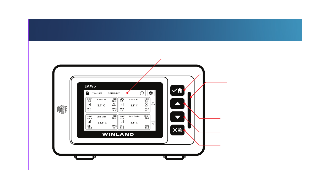
FRONT PANEL
4.7” TOUCHSCREEN
ACCEPT/HOME
LIGHT LED
INCREASE
DECREASE
CANCEL/SILENCE
Page 4
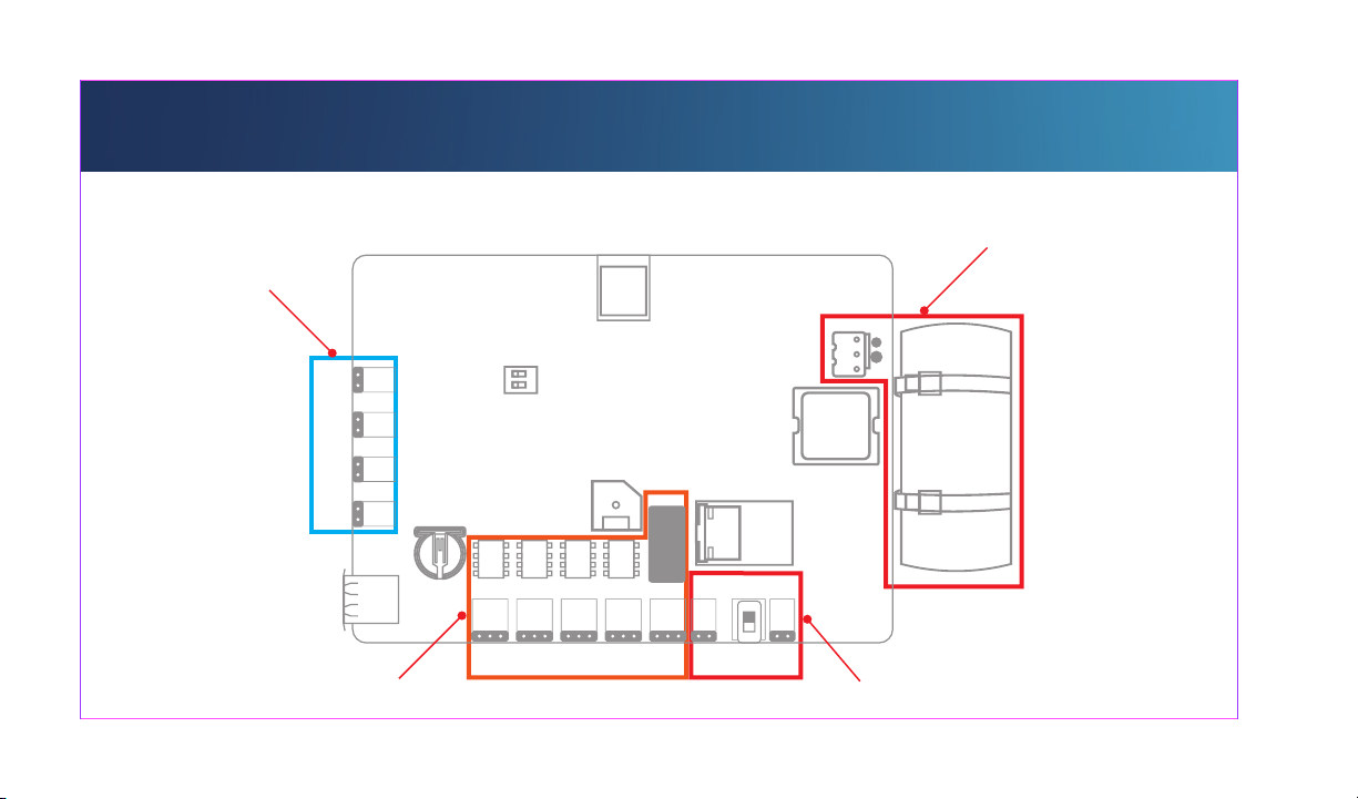
SENSOR INPUTS
(-)
(+)
(-)
(+)
(-)
(+)
(-)
(+)
INPUT #4 INPUT #3 INPUT #2 INPUT #1
BACK PLATE
UPS BATTERY
RELAY OUTPUTS
OUT #1
OUT #2 OUT #3 OUT #4
OUT #5
PWR OUT
(-) (+)
PWR ON
PWR IN
(-) (+)
POWER CONNECTIONS
Page 5
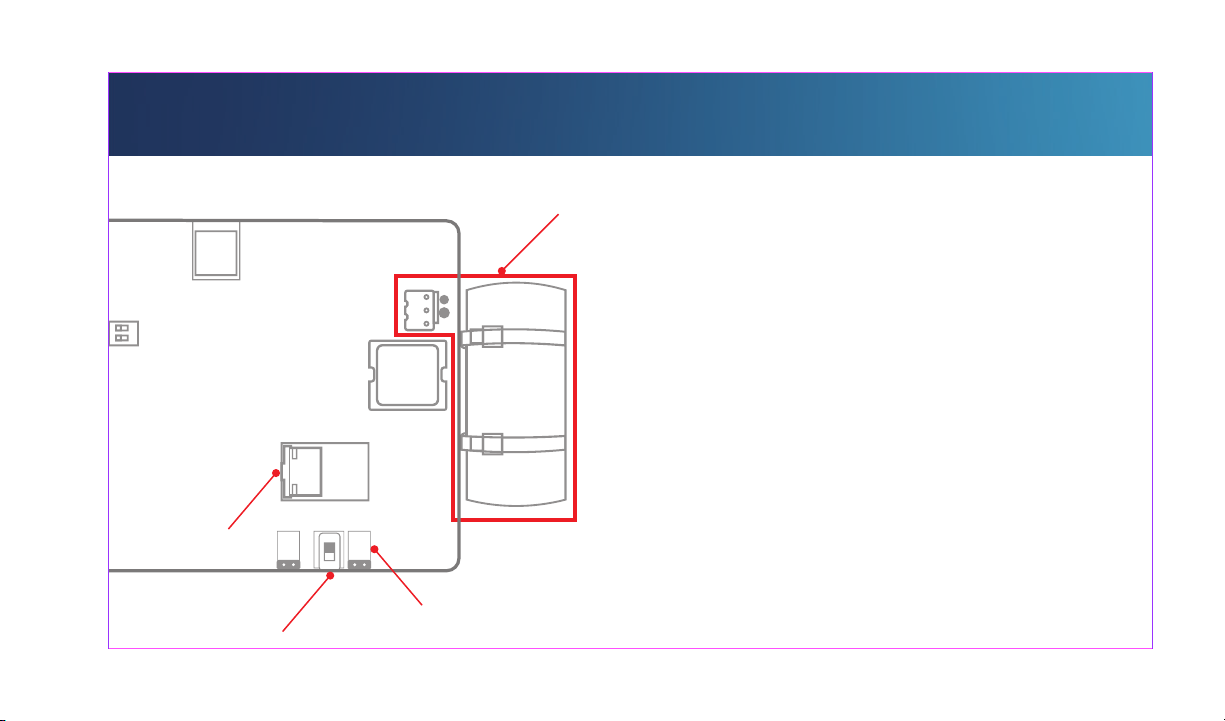
POWER ON
PoE RJ45
POWER SWITCH
PWR OUT
UPS BATTERY
IMPORTANT!
Incorrect polarity can cause personal
injury and / or damage to the unit.
1. Zip tie UPS Battery to PCB.
2. Connect the UPS Battery to the
MOLEX connection on the PCB.
3. Ensure POWER SWITCH, is in the
DOWN (OFF) position.
4. Connect either PoE cable to the RJ45
connector or 12~24V DC @1A power to
PWR IN
PWR ON(-) (+)
(-) (+)
the PWR IN terminal block. Both can
be connected at the same time for
redundancy.
5. Adjust POWER SWITCH from OFF to
POWER CONNECTIONS
ON.
Page 6
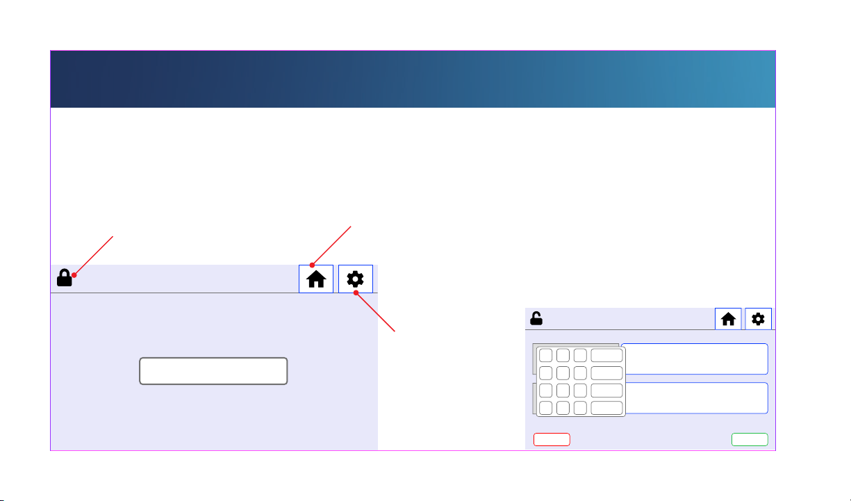
UNLOCK
DEFAULT PIN: 1234
LOCK ICON
7 Jan 2021 5:51 PM (CST)
NO SENSORS
HOME
To UNLOCK the EAPro®-Gateway, press the
LOCK ICON.
Press BLUE Button next to USERNAME to
select USERNAME, then repeat for PIN.
Enter the PIN using the keypad.
MENU
5:51 PM
1 2 3
4 5 6
7 8 9
+
BACK CONFIRM
CANCEL
CLEAR
ENTER
-
0
LOGIN
SUPER ADMIN
.
Page 7
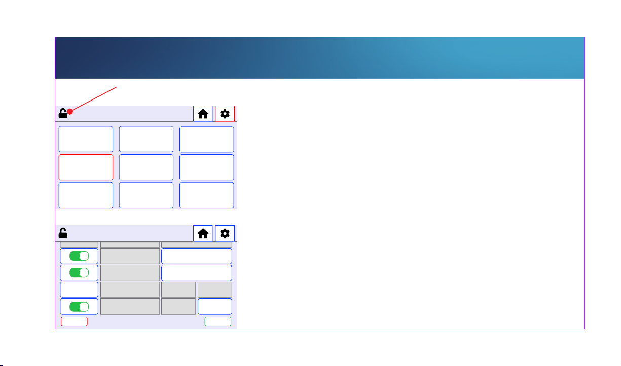
HARDWIRE SENSOR (BLUE) TEMP-L-S
UNLOCKED
5:51 PM
NOTIFICATION
LOGS
SENSORS
SYSTEM
5:51 PM
DEFAULT SETTING NAME
BACK CONFIRM
MAIN MENU
DATA LOGS
RELAYS
USERS
SENSOR TYPE & NAME
NAME
COLLECTION
FREQUENCY
ABOUT
NETWORK
REBOOT
DROP DOWNPROBE TYPE
DROP DOWN
DROP DOWNIN MINUTES
NOTE
Device MUST be unlocked to program/edit/delete
sensors. Not all screens are shown in the quick start
guide. RF Sensor similar to HARDWIRE.
MENU > SENSORS > ADD SENSOR > HARDWIRE >
SELECT SENSOR INPUT >
NOTE
PROBE TYPE is based on your probe/sensor model.
Output will be incorrect if the wrong type is
programmed. NAME can be toggled for common or
custom names. COLLECTION FREQUENCY will
determine sensor logs history.
Winland recommends 15 minutes as a baseline.
PROBE TYPE > NAME > COLLECTION FREQUENCY >
CONFIRM
Page 8
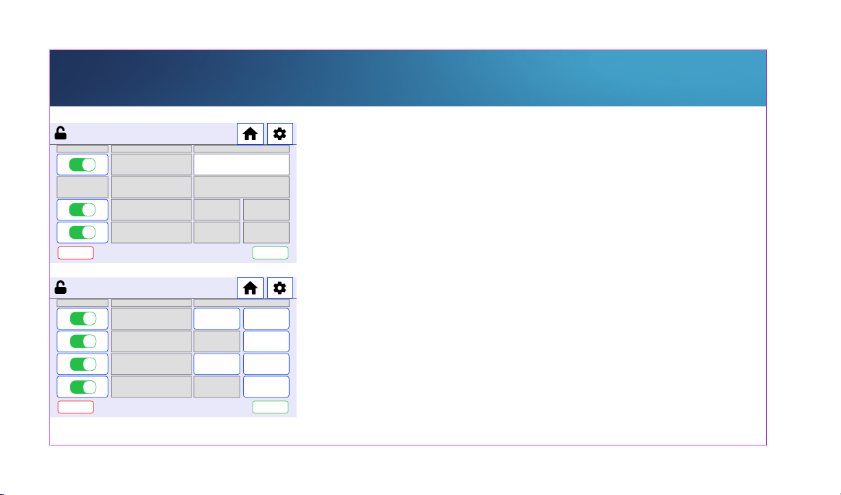
HARDWIRE SENSOR (BLUE) TEMP-L-S
5:51 PM
DEFAULT SETTING NAME
BACK CONFIRM
5:51 PM
ON - OFF SETTING NAME SET POINT
BACK CONFIRM
SENSOR GENERAL
LIGHTS
SENSOR LOW LIMITS
LOW LIMIT
LOW WARNING
DELAY
15.0
17.0
SET POINT
FAHRENHEITUNIT OF MEASURE
0.1HYSTERESIS
ON
ONBUZZER
SELECT
RELAY
RELAY 1 *LOW WARNING
15IN MINUTESLOW LIMIT DELAY
15IN MINUTES
TOGGLE UNIT OF MEASURE > TOGGLE TO ENABLE
LIGHTS AND / OR BUZZER IF DESIRED > CONFIRM >
TOGGLE RELAYS AND LIGHT IF DESIRED > CONFIRM >
NOTE
Not all of the settings are required to program a sensor.
LOW LIMIT: Absolute low value to trigger alarm. Select
which RELAY will activate signal.
LOW LIMIT DELAY: Requires time value for alarm to
become active.
NOTE
WARNING and LIMITS are a dual system notification.
Both can toggle indepentent notifications/relays.
NOTE
Mutiple set points can trigger the same relay.
Page 9
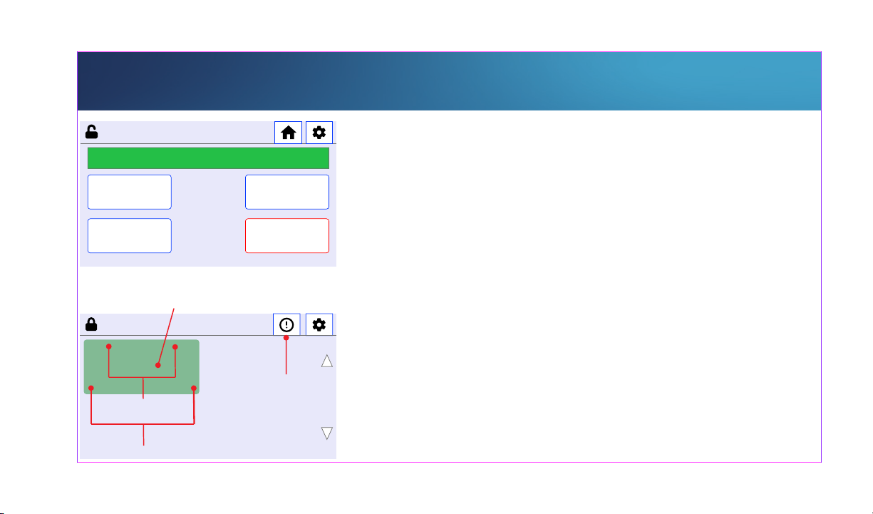
HOME SCREEN
5:51 PM
ADD ANOTHER
SENSOR
HOME DELETE SENSOR
SENSOR ADDED
SENSOR ADDED!
SENSOR READING
7 Jun 2022
5:51:52 PM
LOW
Cooler #1
4.0
8.1 ˚C
MIN MAX
6.31 6.1
HIGH
12.0
HOME
SENSOR LOGS
LIMITS
MIN & MAX
ADJUST SENSOR
DETAILS
NOTE
Repeat process for HIGH LIMITS and HIGH WARNINGS.
SENSOR is added. Select ADD ANOTHER SENSOR,
ADJUST SENSOR DETAILS, HOME to view sensor
information, or DELETE SENSOR to remove a sensor.
NOTE
HOME is the default view once a sensor has been
programmed.
LOW and HIGH limits are based on absolute limit and
NOT on warnings.
MIN & MAX will auto clear on reboot, and can be
manually cleared.
Page 10
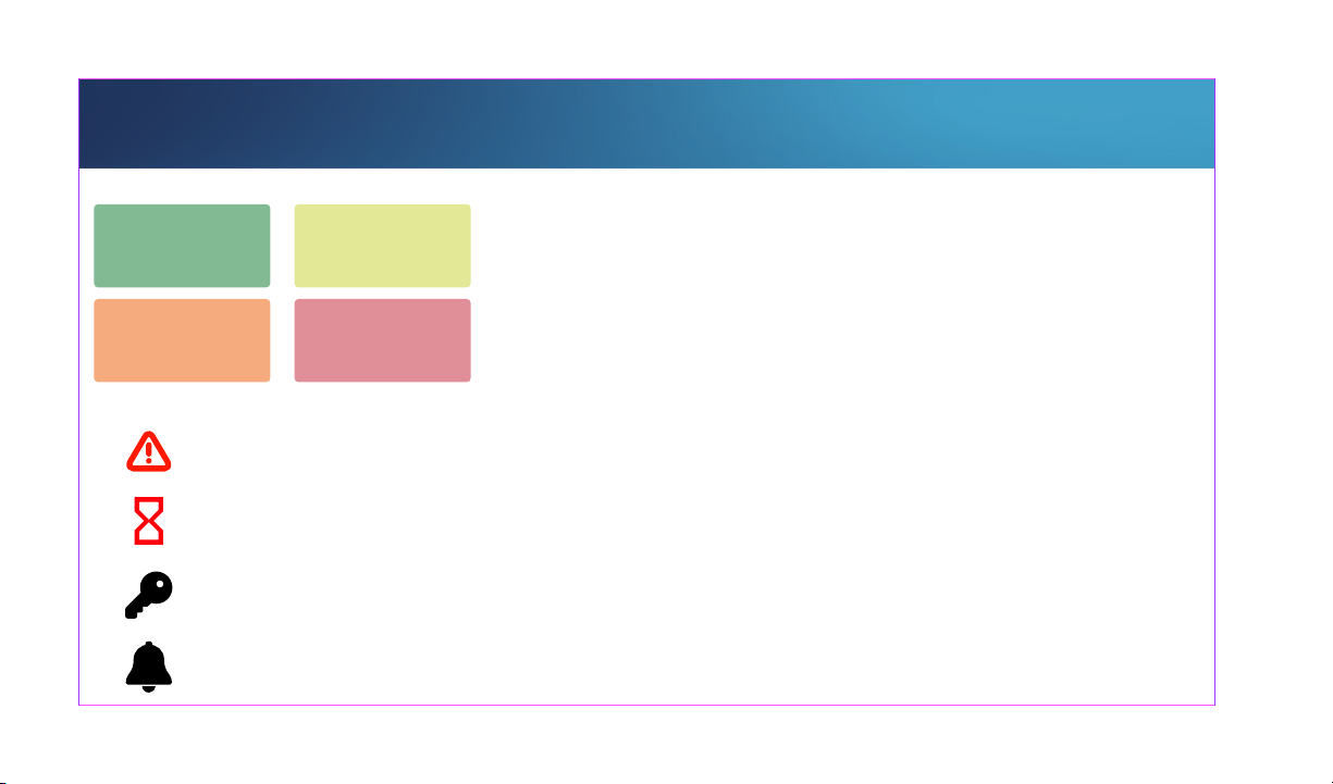
HOME SCREEN
Normal
Condition
Relay Latched
Condition
ICONS
WARNING DELAY
ALARM DELAY
LATCHED RELAY
ACTIVE ALARM
Warning
Condition
Alarm
Condition
NOTE
Each sensor is programmed independantly. Thus, not all
colors will reflect for each sensor.
NOTE
LATCHED relays are not commonly used, and will only
be seen if a relay is programmed to be latched.
Page 11
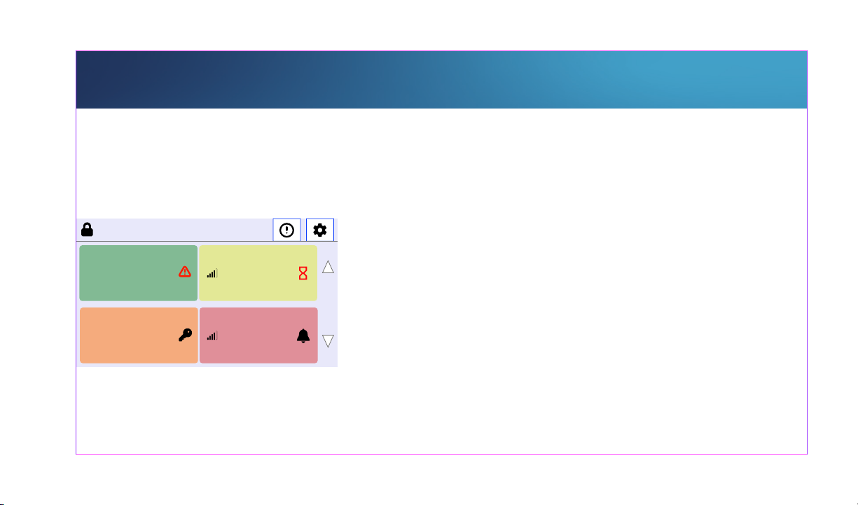
HOME SCREEN
COOLER #1
Within parameters. Pending Warning Condition (delay
active). Warning limits set points will NOT be on display.
7 Jun 2022
5:51:52 PM
LOW
4.0
Cooler #1
HIGH
8.1 ˚C
MINM AX
6.31 6.1
LOW
10.0
Util Room
HIGH
180.0
93.1 PSi
MINM AX
8.91 20.3
HOME
LOW
12.0
Cooler #2
2.0
8.1 ˚C
West Cooler
LOW
33.0
50.2 ˚F
MINM AX
34.2 67.3
HIGH
7.0
MAXMIN
8.11.5
HIGH
48.0
COOLER #2
Warning Condition. Pending Alarm Condition (delay
active).
UTIL ROOM
Within parameters after an Alarm Condition has
cleared, the relay is still latched. Manual clear is
required for relay to stop sending an Alarm Condition.
WEST COOLER
WEST COOLER: Active Alarm Condition.
Page 12
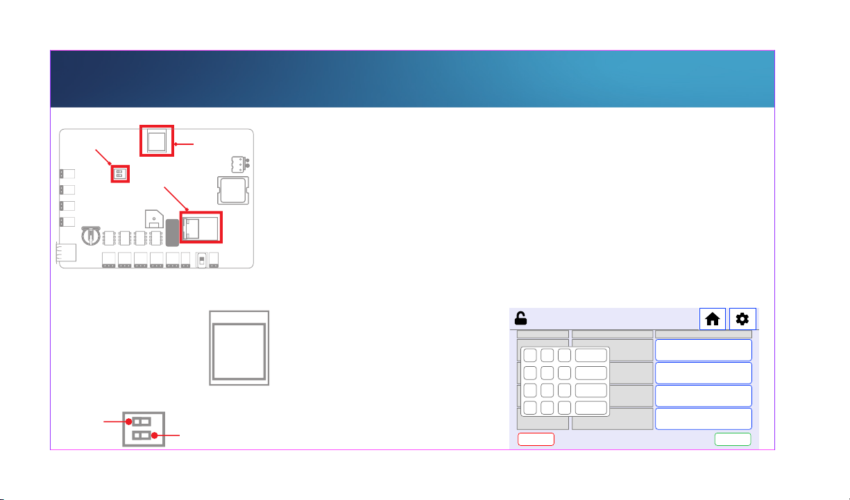
NETWORK ETHERNET
NETWORK TOGGLE
(-)
(+)
(-)
(+)
(-)
(+)
(-)
(+)
INPUT #4 INPUT #3 INPUT #2 INPUT #1
OUT #1
OUT #1 OUT #1 OUT #1 OUT #1 PWR ON
<-OFF ON->
WI-FI
PoE RJ45
WI-FI Chip
PWR OUT
(-) (+)
RJ45
PWR IN
(+) (-)
WI-FI
Chip
NOTE
Ensure the Network Toggle is set properly for your
application. WI-FI Progamming similar.
MENU NETWORK > EDIT ETHERNET >
Enable/Disable DHCP > Follow prompt to enter IP settings
> CONFIRM > Press OK on prompt.
5:51 PM
1 2 3
4 5 6
7 8 9
0
+
BACK CONFIRM
NETWORK - HARDWIRE
SETTING NAME SET POINT
CANCEL
IP
CLEAR
ENTER
.
-
DISABLEDDHCP
192.168.0.101
255.255.255.0SUBNET
192.168.0.10PRIMARY DNS
Page 13
INSIGHT
BACK
SN: 000-0AB8C
KEY: 41FA-9A11
WIFI:
XX:XX:XX:XX:XX:XX
192.168.0.1
255.255.255.0
192.168.0.10
8.8.8.8
192.168.0.10
ETHERNET MAC
XX:XX:XX:XX:XX:XX
192.168.0.2
Guides
NOTE
INSIGHT is a subcription based system. It is not
required to operate this device. For more information
about INSIGHT:
CONFIRM
MENU > NETWORK > CLOUD ENABLE > SYNC (select
option) > CONFIRM. Press OK on Prompt.
SN & Key provided at: MENU > ABOUT > CONFIRM.
Log into INSIGHT: www.winlandinsight.com
Use the SN&KEY provided to:
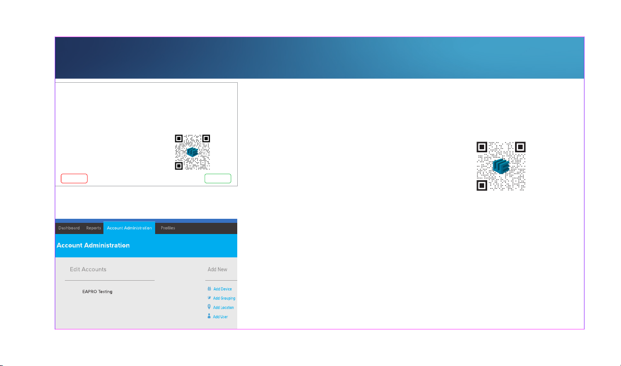
Account Administration > Add Device
Page 14

INFORMATION
For the complete EAPro® User Manual,
including product specifications,
user-interface details, and warranty
details, please follow the QR code:
https://winland.com
http://manual.eapro.winland.com
800.635.4269
© 2022 Winland Electronics
D-011-0178 Rev. A (06/2022)
 Loading...