

Winkhaus BXP BS, BXP 61 BS User Manual
User Guide
Programming Device BXP BS (5044551)/BXP 61 BS (5044573)

Table of Contents
Caution: Please read this user guide and the safety instructions carefully, before proceeding to use the programming device.
An inappropriate use will lead to a loss of all warranties!
1. Description of components Page 3
2. Standard accessories Page 4
3. First steps Page 4
3.1 Switching on / o Page 4
3.2 Transfer of data Page 4
3.3 Programming device on site Page 5
3.4 Menu structure Page 5
4. Application notes Page 5
4.1 Identifying components Page 5
4.2 Programming components Page 6
4.3 Open transactions / faulty transactions Page 6
4.4 Battery replacement list / battery status list Page 6
4.5 Reading out events / showing events Page 7
4.6 Identifying ID medium Page 7
4.7 Synchronising component time Page 8
4.8 Power adapter function Page 8
4.9 Battery replacement function Page 9
4.10 Choosing a system Page 9
4.11 Settings Page 9
5. Power supply / Security notes Page 10
5.1 BXP power supply and security notes Page 10
5.2 Charging the batteries Page 10
6. Ambient conditions Page 11
7. Error codes Page 11
8. Declaration of Confirmity Page 12
Aug. Wi nkha us Gmb H & Co. KG ∙ Hes senweg 9 ∙ 4 8157 Münste r ∙ T +49 251 4908 - 0 ∙ z utritt sorga nisation@w inkha us.d e ∙ www.win khau s.de
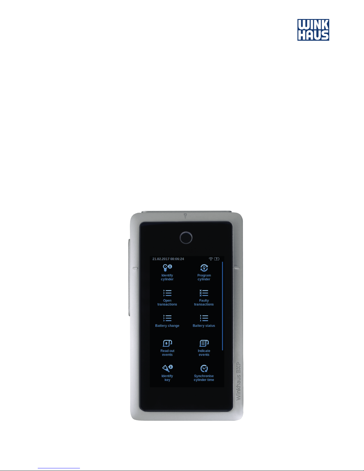
Progra mming device BXP
3
User Guide
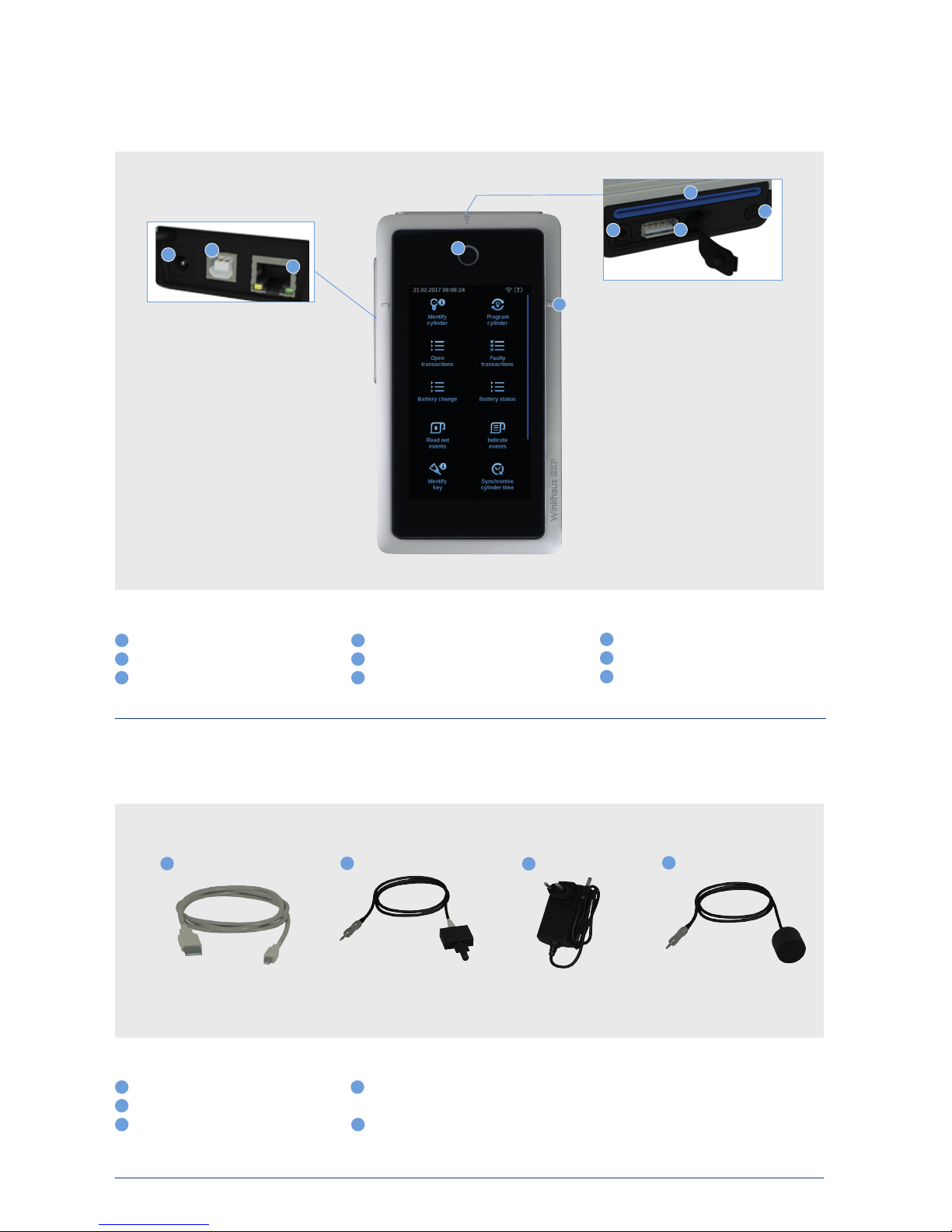
1. Description of components:
1. Standard accessories (included in the scope of delivery)
Fig. 1: BXP progr amming device
Connection socket fo r power su pply un it
USB- B port
RJ 45 interface
Key inser tion slot for ele ctroni c key
Conta ct surface for RFID c ards
Connection socket for adapter cable
USB- A port
Slot for R FID ca rds (e. g. pro gramm ing card)
On / off switch
1 4
7
2 5
8
3 6
9
Fig. 2: Standard accessories
USB ca ble typ e A/B
Connection cable t ype A1 to cylinder
Power sup ply unit f or exter nal powe r suppl y
Connection cable t ype A5 to reader and
electronic door handle
Withou t figure: conn ectio n cable type A6 to
cylind er typ e 6x (only for va riant BX P 61 BS)
1
4
2
3 5
1
2
3
4
1
6
7
8
3
9
5
4
2
Aug. Wi nkha us Gmb H & Co. KG ∙ Hes senweg 9 ∙ 4 8157 Münste r ∙ T +49 251 4908 - 0 ∙ z utritt sorga nisation@w inkha us.d e ∙ www.win khau s.de
Progra mming device BXP
4
User Guide
Connect the plug-in power supply unit to the BXP. The device starts
automatically. Make sure that the programming device’s drivers have been
properly installed. As a rule the drivers are automatically installed on
installation of the administration software. But they can also be found on the
attached installation CD.
Connect the programming device to the PC by means of the attached USB
cable. Launch the electronic locking system administration software on your
PC and follow the instructions on the screen.
The software will then check whether a firmware update is available for your
programming device. If there is, the update must be installed.
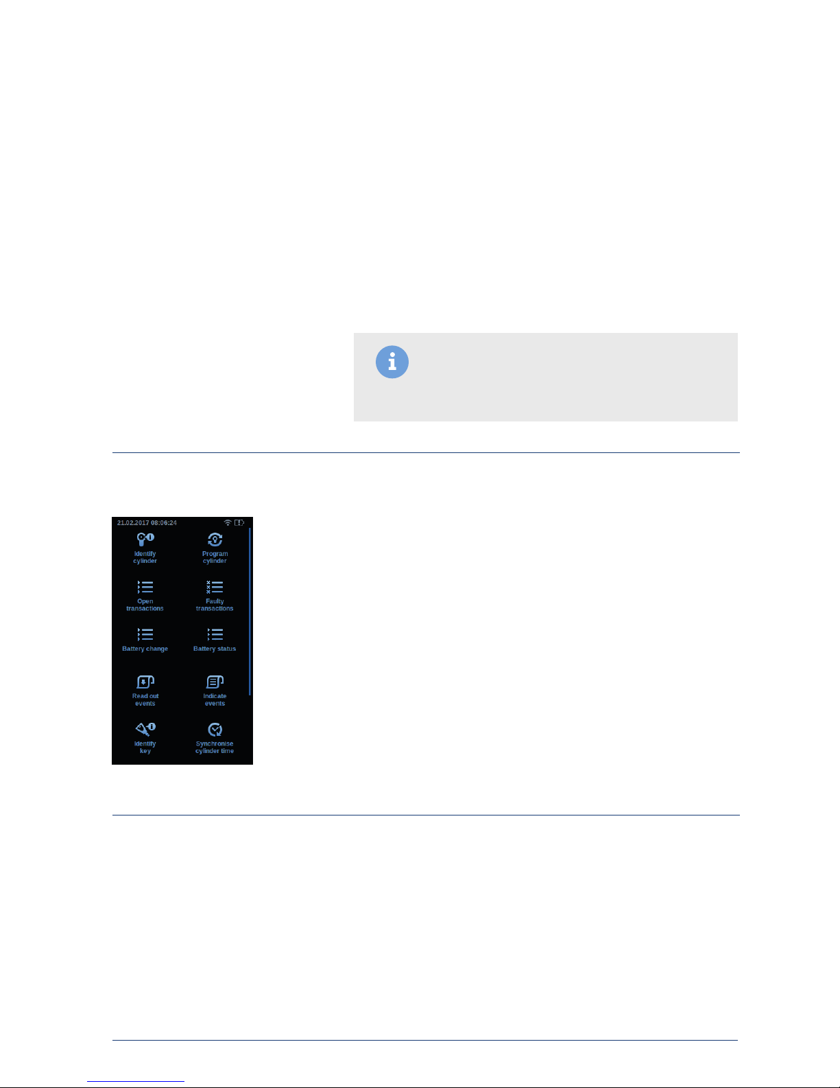
To switch on, please push the on/o switch (9). The ring around the key
insertion slot lights up blue and a short beep is heard. Then the Winkhaus
logo and a progress bar appear. After that the start window is shown in the
display (fig. 3).
If the on/o switch (9) is pushed briefly, the system will ask you whether you
want to switch o the BXP.
In case the device does no longer respond, it can be switched o by pushing
the on/o switch very long (at least 20 s).
You can find the individual setting of the interface in the sof tware’s
corresponding installation instructions. The programming device is able to
communicate with the administration software via USB, LAN or W-LAN (see
4.11 Settings).
3. First Steps:
3.1 Switching on / off:
3.2 Transfer of data:
Fig. 3: St art window
Note: On installing the BXP firmware update, please
ensure that no transactions (data) are open in the
programming device memory in the process.
Aug. Wi nkha us Gmb H & Co. KG ∙ Hes senweg 9 ∙ 4 8157 Münste r ∙ T +49 251 4908 - 0 ∙ z utritt sorga nisation@w inkha us.d e ∙ www.win khau s.de
Progra mming device BXP
5
User Guide
The preparation on the PC takes place by means of the administration
software. After the requested information has been transferred to the BXP,
please connect the device to the blueSmart component in question using
the suitable adapter cable.
Please note: You need the type A1 adapter for cylinders. Insert the adapter,
turn it about 45° and it will lock into position. You need to use a type A5
adapter if you are using readers and the intelligent door handle fitting
system.
For use of double knob cylinders of the 6x series you need the programming
device BXP BS 61 (5044573) and the adapter type A6 (included in the
BXPBS 61 scope of delivery).
3.3 Programming device on site:
3.4 Menu structure:
4 Application notes:
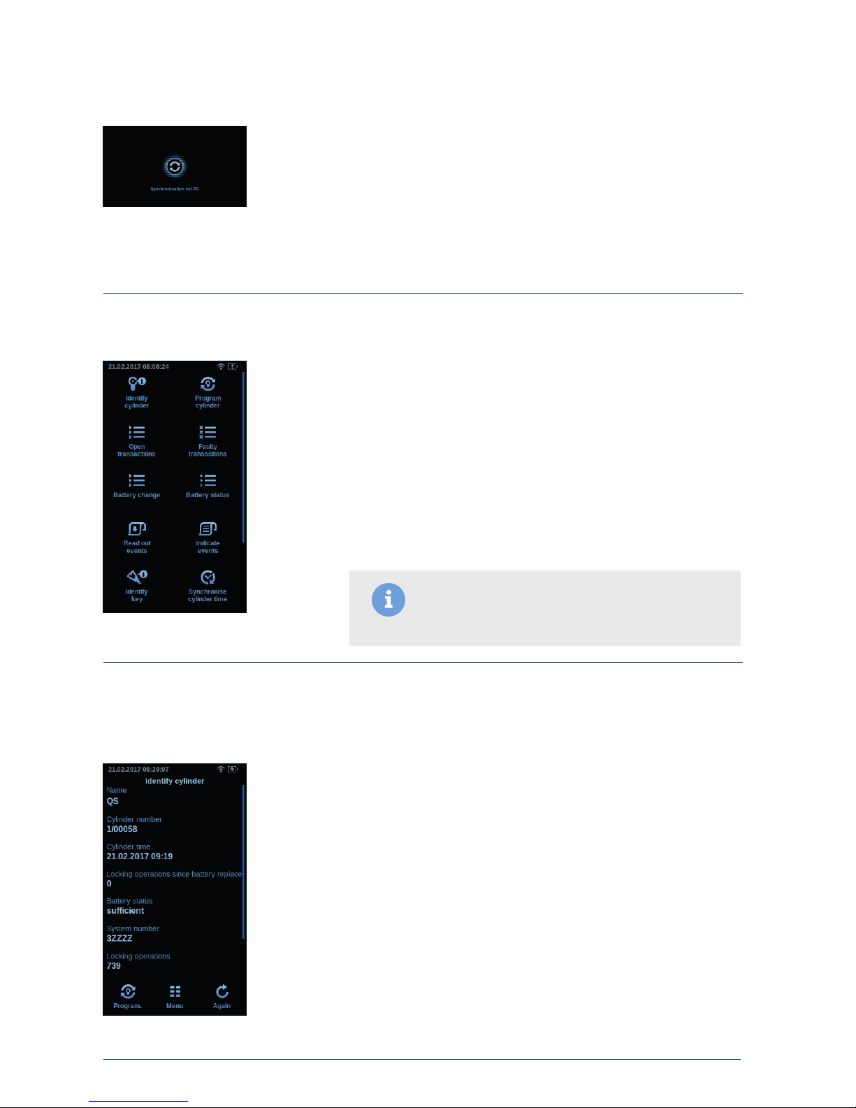
4.1 Identifying components:
Fig. 5: St art me nu
Fig. 6: I dentif ying cylinde r
• Identifying components
• Programming components
• Open transactions
• Faulty transactions
• Battery replacement list
• Battery status list
• Reading out events
• Showing events
• Identif ying ID medium
• Synchronising component time
• Power adapter function
• Battery replacement function
• Choosing a system
• Settings
If the locking system or the locking number should no longer be readable,
the cylinder, the readers or the fittings (components) can be identified. For
instance, connect the BXP to the cylinder and select “Identifying
component”. The action is automatically started. All relevant data is indicated
(see table). Scroll down for further information.
Indicated information
• Component name
• Component number
• Component time
• Locking events since battery replacement
• Battery status
• System number
• Amount of locking events
• Component status
• Component ID
Fig. 4: Synchronisation
Note: The navigation takes place via touching of the
touch display. The progress bar on the right display edge
shows the position.
 Loading...