

Winkhaus blueChip BC TI, blueSmart BS TI, blueChip BC TE, blueSmart BS TE Installation Manual
Installationsanleitung
blueChip Leser BC TI und BC TE
blueSmart Leser BS TI und BS TE
Verschaltung Bx TI
L
230 V AC 12 V AC 230 V AC 12 V AC
MP
Erde
Leser Bx TI
Summer
Relais
Kontaktansicht: Ruhestellung
Erdungsadapter Erdungsadapter
1
2
3
4
5
Power V1
Power V2
Relais NO
Relais NC
Relais COM
Bx TI/TE: LED- und Summer-Signale
Freilaufdiode
bipolar
Türöner
12 V AC
L
MP
Leser Bx TI
Verschaltung bei
Ruhestrombetrieb
Power V1
Power V2
Relais NO
Relais NC
Relais COM
Freilaufdiode
bipolar
Türöner
12 V AC
Einbauhinweise
Werden mehrere Leser montiert, ist zwischen den Lesern ein Abstand von mindestens 20 cm einzuhalten. Werden induktive
Lasten geschaltet, muss zum Schutz der
Kontakte die beiliegende Löschdiode (Frei
laufdiode) parallel zur Last eingebaut werden. Wird das mitgelieferte Kabel verkürzt
oder verlängert kommt es zu Beeinträch
tigungen der Leserreichweite. Erdungsadapter zwischen Potential Erde (PE) und V1
oder V2 zum Schutz vor außergewöhnlich
hohen Netzstörspannungen. Das Anlegen
einer höheren Spannung führt zum Zerstö
ren des Lesers. Es wird empfohlen, ein geregeltes Netzteil mit einer Ausgangsspannung
von 12 V einzusetzen. Im spannungsfreien
Zustand des Lesers ist kein Kontakt zwi
schen „NC“ und „COM“ gegeben!
Verschaltung Bx TE
Antenneneinheit vom Bx TE
nur bei Leser mit abgesetzter Antenne
Summer
Kabellänge 3,0 m, 3 Paare, verseilt
Technische Daten und Anschlussbelegung
Versorgungsspannung an V1 u. V2: 8 V bis 16 V DC oder AC 50 Hz
(Low Power Source max. 8 A; max. 100VA)
Relaisanschluss NO = normal open, Arbeitsseite
Relaisanschluss NC = normal closed, Ruhesseite
-
Relaisanschluss COM = common, Mittenanschluss
Schaltstrom/Schaltspannung max.: 1 A/30 V
Stromaufnahme bei 12 V DC: 80 mA
Schutzart: Siedle: IP 54
Gira und bticino: IP 20
Temperaturbereich: Bx TE Antenneneinheit: -25 °C bis +60 °C,
Steuereinheit: -10 °C bis +55 °C
Bx TI: -10 °C bis +55 °C
-
Leseabstand mit Schlüssel: typ. 10 mm
Leseabstand mit Karte: typ. 40 mm
Montage: vorzugsweise in Standard Unterputzdose (UP55)
oder Aufputzdose kombiniert mit entsprechendem
Schalterdesign (z.B. Gira, Siedle, bticino)
Steuereinheit Bx TE
Anschluss an Gleichspannung DC
oder Wechselspannung AC
AN- Litze grau
AN+ Litze rosa
GND Litze weiß
LDR Litze braun
LDG Litze grün
SUM Litze gelb
11
12
Relais
13
14
15
16
Kontaktansicht: Ruhestellung
1
2
3
4
5
Power V1
Power V2
Relais NO
Relais NC
Relais COM
Erdungsadapter
AC / = DC
AC / = DC
Erde
Beschreibung
LED Grün
LED Rot LED Gelb Summer
Anzeige des Systemzustandes
Normalzustand, Dauerfreigabe inaktiv
Normalzustand, Dauerfreigabe aktiv
Verhalten des bei einer Buchung im Normalzustand
Berechtigter Schlüssel 200 ms
Unberechtigter Schlüssel 750 ms
Berechtigter Schlüssel (Dauerfreigabe aktiv) 12 ms
Unberechtigter Schlüssel (Dauerfreigabe aktiv) 12 ms
Aktivieren der Dauerfreigabe 2 x 200 ms
Deaktivieren der Dauerfreigabe
(LED Rot blinkend wie Summersignal, danach LED Gelb blinkend)
2 x 750 ms
Anzeige eines Fehlerzustandes
Dieser Zustand führt zum Deaktivieren der Dauerfreigabe
Fehler Uhrzeit, Dauerfreigabe inaktiv
Fehler Uhrzeit, Dauerfreigabe aktiv
Verhalten bei einer Buchung im Fehlerzustand
Fehler
In diesem Zustand ist keine Buchung möglich
Fehler Uhrzeit
Im Wechsel mit der Signalisierung einer normalem Buchung
10 x 50 ms
Verhalten während des Programmiervorgangs
Nach jedem empfangenen Telegramm ein 3 ms LED Gelb Signal
= LED an = LED blinkend
Hiermit erklärt die Aug. Winkhaus GmbH & Co. KG, dass sich das Gerät in Übereinstimmung mit den grundlegenden Anforderungen und den anderen relevanten Vorschriften der Richtlinie 2014/53/EU bendet. Die Langfassung der EU-Konformitätserklärung
nden Sie unter: www.winkhaus.com/konformitaetserklaerungen
ZO MW 062017 Print-no. 997 000 225 Alle Rechte und Änderungen vorbehalten.

Installation manual
blueChip Reader BC TI and BC TE
blueSmart Reader BS TI and BS TE
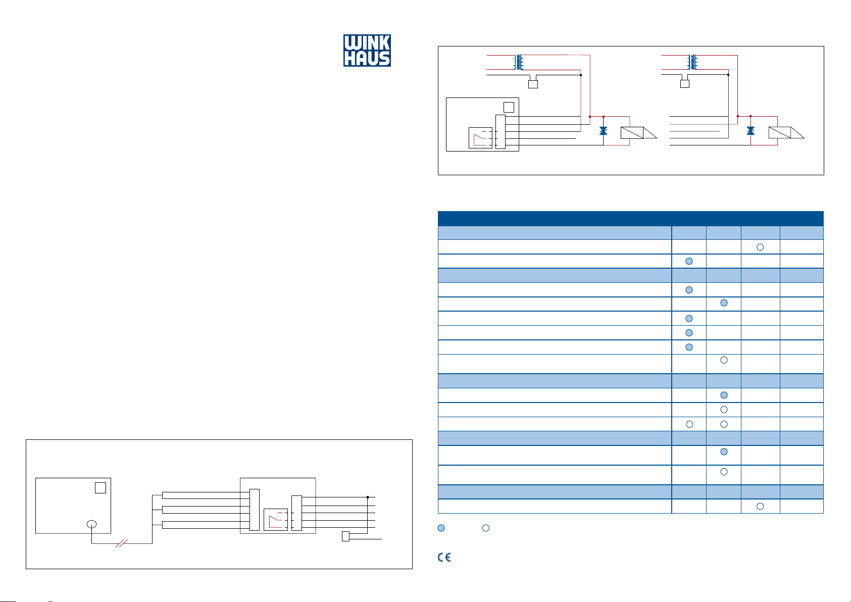
Wiring Bx TI
L
230 V AC 12 V AC 230 V AC 12 V AC
MP
ground
Reader Bx TI
Buzzer
Relay
Contact shown in the open position
grounding adapter grounding adapter
1
2
3
4
5
Bx TI/TE: LED and buzzer signals
Power V1
Power V2
Relay NO
Relay NC
Relay COM
recovery diode
bipolar
ground
door opener
12 V AC
L
MP
Reader Bx TI
Wiring during closed-circuit
operation
Power V1
Power V2
Relay NO
Relay NC
Relay COM
recovery diode
bipolar
door opener
12 V AC
Installation instructions
If several readers are being installed, then a
minimum distance of at least 20 cm must
be maintained between readers. If induc
tive loads are switched, then a quenching
diode must be installed parallel to the load
for protecting the contacts. If the supplied
cable is shortened or lengthened, then the
reading range of the reader may be nega
tively inuenced. Grounding adapter between potential earth (PE) and V1 or V2 for
protection from extraordinarily high inter
ference voltage. Connection to a higher voltage will cause the destruction of the reader.
It is recommended to use a regulated power
supply, which provides an output voltage
of 12V. In a voltage-free condition of the
reader, no contact exists between „NC“ and
„COM“. If an authorised key is held in front
of the reader for more than three seconds,
then a continuous release is activated.
Wiring Bx TE
Antenna unit of Bx TE
Only with readers that have a separated antenna
Buzzer
Cable length 3.0 m, 3 pairs, stranded
Technical data and pin conguration
Supply voltage at V1 and V2: 8 V bis 16 V DC oder AC 50 Hz
(low power source max. 8 A; max. 100VA)
-
Relay connection NO = normal open, operating side
Relay connection NC = normal closed, non-operating side
Relay connection COM = common, middle pin
Switching current/
switching voltage max.: 1 A/30 V
-
Power consumption at 12 V DC: 80 mA
Protection class: Siedle: IP 54
Gira and bticino: IP 20
Temperature range: Bx TE antenna unit: -25 °C to +60 °C,
Control unit: -10 °C to +55 °C
Bx TI: -10 °C to +55 °C
Reading interval with key: typically 10 mm
Reading interval with card: typically 40 mm
Assembly: preferably in standard ush mounted box (UP55)
or surface-mounted box combined with a suitable
switch design ( e. g. Gira, Siedle, bticino)
Control unit Bx TE
Connection on direct-current (DC)
or alternating-current (AC)
ON- grey lead
ON+ pink lead
GND white lead
LDR brown lead
LDG green lead
SUM yellow lead
11
12
Relay
13
14
15
16
Contact shown in the open position
1
2
3
4
5
Power V1
Power V2
Relay NO
Relay NC
Relay COM
grounding adapter
AC / = DC
AC / = DC
ground
Description
Green LED
Red LED Yellow LED Buzzer
Display of system status
Normal state, continuous release inactive
Normal state, continuous release active
Behaviour in the event of a normal state entry
Authorised key 200 ms
Unauthorised key 750 ms
Authorised key (continuous release active) 12 ms
Unauthorised key (continuous release active) 12 ms
Activation of continuous release 2 x 200 ms
Deactivation of continuous release
(Red LED blinks along with a buzzer signal, after that yellow LED blinks)
2 x 750 ms
Display of an error condition
This condition leads to the deactivation of the continuous release
Error clock time, continuous release inactive
Error time, continuous release active
Behaviour in the event of a transaction during an error state
Error
No transaction is possible in this state
Error time
Alternating with the signalling of a normal transaction
10 x 50 ms
Behaviour during a programming procedure
3 ms yellow LED signal after each received data frame
= LED on = LED blinks
Aug. Winkhaus GmbH & Co. KG declares herewith that the device is compliant with the basic requirements and the relevant rules in
directive 2014/53/EU. The long version of the declaration of EU conrmity is available at:
www.winkhaus.com/konformitaetserklaerungen
ZO MW 062017 Print-no. 997 000 225 All rights, including the right of alteration, are reserved.
 Loading...