

Winkhaus blueCompact Operating Manual
Operating manual
blueCompact
Read the instructions prior to performing any task!

Aug. Winkhaus GmbH & Co. KG
Hessenweg 9
48157 Münster
Germany
Telephone: 49 251 4908-0
Fax: +49 251 4908-145
Internet: www.winkhaus.com
Wink-29491-DE, 2, en_GB
© Aug. Winkhaus GmbH & Co. KG 2015
30.06.2016blueCompact Electronic locking system2

Supplemental directives
What is blueCompact?
Operating systems and smartphone versions
Customer Service
blueCompact is an electronic locking system which comprises a maximum of 99 keys and 25 cylinders. The main
components of this locking system are the app and an
active electronic key which allow you to activate, manage
and code keys and cylinders.
You need one of the following operating systems for the
app:
n Android Version 4.4 or higher
n iOS Version 7 or higher
Smartphones must feature Bluetooth 4.0 or higher.
Display of the app needs to be enhanced for use on tablet
PCs.
Our Customer Service will be happy to answer any questions that you may have.
Aug. Winkhaus GmbH & Co. KG
Hessenweg 9
48157 Münster
Germany
+49 251 4908-110
+49 251 4908-145
www.bluecompact.com
Winkhaus Ibérica S.A.
PAE La Marina
C./ de la Creativitat, 7
08850 Gavà/Barcelona
Spain
+34 936.334.470
+34 93 6334471
www.bluecompact.com
30.06.2016 blueCompact Electronic locking system 3

Supplemental directives
F+W France SARL
6, Rue de la Maison Rouge
Bâtiment D
77185 Lognes
France
+33 160.951.622
+33 160.951.617
www.bluecompact.com
Winkhaus Nederland B.V.
Landauer 29
3897 AB
Zeewolde
Netherlands
+31 365.227.744
+31 365.224.333
www.bluecompact.com
Winkhaus Austria GmbH
Oberfeldstrasse 24
5082 Grödig
Austria
+43 6.246.722.260
+43 624.672.226.145
www.bluecompact.com
30.06.2016blueCompact Electronic locking system4
Supplemental directives
Winkhaus Polska Beteiligungs
spółka z ograniczoną
odpowiedzialnością sp.k.
ul. Przemyslowa 1
64 130 Rydzyna
Poland
+48 655.255.700
+48 655.255.800
www.bluecompact.com
Purpose of the instructions
Symbols in the instructions
These instructions ensure safe handling of the blueCompact locking system.
n Read the instructions before starting any work.
n Always comply with specifications such as operational
and safety instructions.
n Keep instructions in a safe place ready for future use.
n Also provide the instructions to the new owner if you
pass on the product.
n The images are provided to ensure basic understanding
and may differ from the actual version that you have.
Warnings are identified in these operating instructions by
the use of symbols. The safety information is preceded by
signal words emphasizing the severity of the risk.
WARNING!
This combination between a symbol and a signal
word indicates a potentially dangerous situation
which could result in death or severe injury if not
prevented.
NOTICE!
This combination of symbol and signal word
indicates a potentially dangerous situation which
could result in damage to property if not prevented.
30.06.2016 blueCompact Electronic locking system 5
Supplemental directives
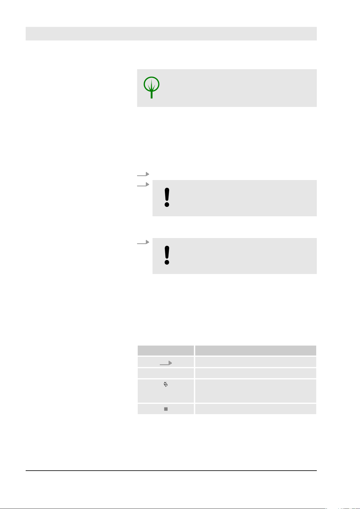
ENVIRONMENTAL PROTECTION!
This combination of symbol and signal word
indicates potential hazards to the environment.
Safety instructions in the operating instructions
Safety instructions may refer to specific, individual operating instructions. Such safety instructions are embedded
into the operating instructions, so that they do not interrupt the flow of the text when users carry out an action.
The signal words described above are used.
Example:
1. Insert cylinder.
2.
NOTICE!
Physical damage due to face plate screws
screwed at an angle.
Screw the face plate screw, so that it is straight when
it enters the cylinder thread.
3.
NOTICE!
Physical damage due to over-tightening of
screw.
Use a screwdriver to tighten face plate screw by hand.
The cylinder is installed.
ð
Other symbols
The following symbols are used to highlight operational
instructions, results, lists, references and other elements in
these instructions:
Identification Explanation
Step-by-step operational instructions
ð
Results of required steps
Reference to paragraphs in these
instructions and additional applicable
documents
Lists with no fixed order
30.06.2016blueCompact Electronic locking system6
Tips and recommendations
Supplemental directives
This symbol highlights useful tips and recommendations as well as information for efficient,
trouble-free operation.
Target group
Step by step to completion – the
'Instructions' menu
Example step-by-step instructions: Incorporate cylinder
Skilled non-professionals and maintenance staff who have
the following expertise as a minimum:
n Fitting and dismounting of cylinders
n Handling smart phones and operating app interfaces
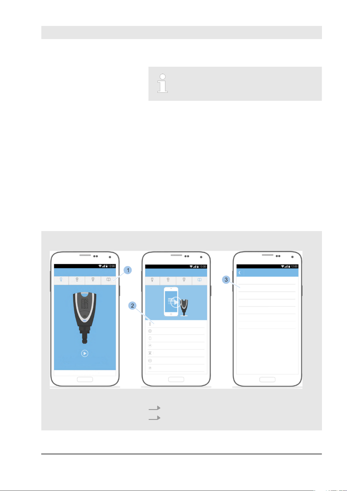
Multimedia instructions:
n In addition to this printed version, you can also access
the instructions in the main menu in the app.
n The step-by-step instructions for the app explain the
different processes using images and texts, even
without an Internet connection.
n You can also see the instructions with the app as an ani-
mated video clip if you have access to the Internet.
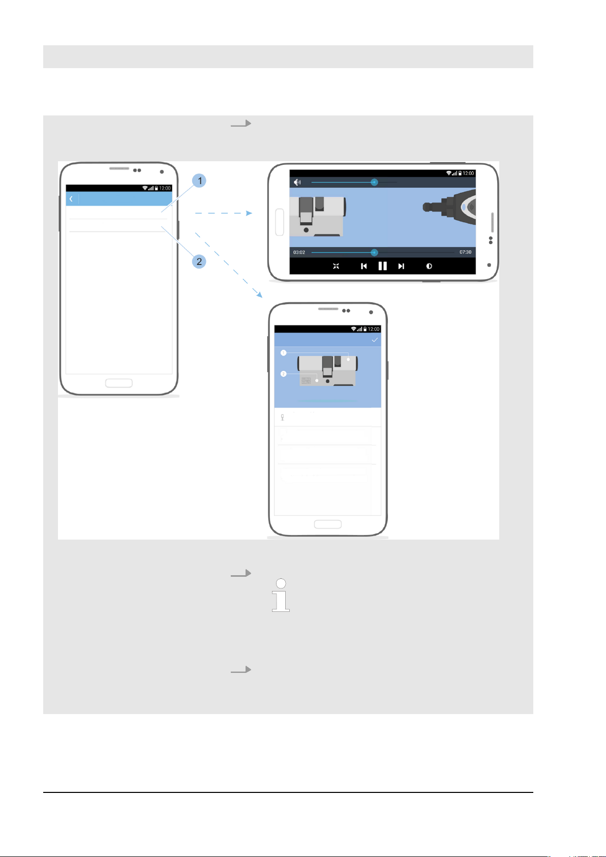
Fig. 1: Open instructions
1. Touch the Instructions menu (1) on the main menu.
2. Select Installation chapter (2).
This then displays the sub-sections.
ð
30.06.2016 blueCompact Electronic locking system 7
Supplemental directives
3. Select Add cylinder chapter (3).
You can select the instructional video or the step-
ð
by-step instructions.
Fig. 2: Select instruction type
4.
You can only open the instructional
video if you have access to the Internet.
Touch ‘Video instructions’ (1) to open the instructional video.
5. Touch ‘Step-by-step instructions’ (2) to look at the
step-by-step instructions.
30.06.2016blueCompact Electronic locking system8

Supplemental directives
The activation set is the basis for the locking system.
Ä
Chapter 1.1 ‘Compile components as required’
on page 14
The activation set also includes a quick start guide. This
quick start guide contains:
n Instructions to install app obtained from Google Play
Store/App Store
n QR code for the relevant platform
n Safety and disposal instructions
n Start guide (the first few steps before starting the app)
30.06.2016 blueCompact Electronic locking system 9

Supplemental directives
30.06.2016blueCompact Electronic locking system10

Table of contents
Table of contents
1 Product overview..................................................................... 13
1.1 Compile components as required.............................. 14
1.2 Key........................................................................................ 14
1.2.1 Active keys...................................................................... 14
1.2.1.1 Use user key function................................................ 16
1.2.1.2 Use internal power function................................... 17
1.2.1.3 Use external power function................................. 18
1.2.2 Master key....................................................................... 18
1.2.3 Passive key..................................................................... 19
1.2.4 Adapter............................................................................ 19
1.3 Activation card................................................................ 20
1.4 PUK card............................................................................ 20
1.5 Cylinder................................................................................ 21
2 Security....................................................................................... 25
2.1 Intended use..................................................................... 25
2.2 Safety when installing cylinders in fire doors..... 26
2.3 Safety when installing cylinders in emergency
doors................................................................................... 26
2.4 Instructions on integrating alarm systems.......... 27
2.5 The administrator's responsibilities........................ 27
2.6 Hazards for people........................................................ 28
2.7 Risk to property............................................................. 29
2.8 Risk of break-in................................................................ 31
3 Transport and store................................................................ 33
3.1 Labelling on the packaging........................................ 33
3.2 Transport and unpack.................................................. 33
3.3 Storing............................................................................... 34
4 Select and install cylinder.................................................... 37
4.1 Dismount old cylinder.................................................. 40
4.2 Determine cylinder type............................................ 40
4.3 Determine cylinder length.......................................... 41
4.4 Install old cylinder........................................................ 44
4.5 Prepare cylinder installation..................................... 46
4.6 Install cylinder Type 01, Type 02 and Type 05.. 47
4.7 Install cylinder Type 04 and Type 04 MK........... 49
4.8 Install cylinder Type 21 and Type 22...................... 52
5 Install app................................................................................... 55
6 Manage locking system........................................................ 57
6.1 Initialise master key....................................................... 57
6.2 Log in................................................................................. 59
6.3 Add and manage key.................................................. 60
6.3.1 Add key to locking system..................................... 60
30.06.2016 blueCompact Electronic locking system 11

Table of contents
6.3.2 Manage keys................................................................ 62
6.3.3 Identify key................................................................... 63
6.3.4 Delete key..................................................................... 64
6.4 Add and manage cylinder.......................................... 65
6.4.1 Add cylinder to locking system............................ 65
6.4.2 Change cylinder name............................................. 66
6.4.3 Identify cylinder......................................................... 66
6.4.4 Check the cylinder battery charge status....... 68
6.4.5 Issue and withdraw locking authorisations..... 69
6.4.6 Delete cylinder............................................................. 71
6.5 Show and send locking events................................. 72
6.6 Open system information.......................................... 74
6.7 Open and forward locking plan............................... 75
6.7.1 Forward locking plan manually.............................. 77
6.7.2 Set locking plan change reminder....................... 78
6.8 Issue remote authorisation........................................ 79
7 Close............................................................................................. 85
8 Install software updates....................................................... 87
8.1 Transfer data to the master key and active
keys...................................................................................... 87
8.2 Transfer data to cylinder............................................. 91
9 Cleaning and maintenance.................................................. 95
9.1 Test cylinder and clean key........................................ 95
9.2 Replace batteries........................................................... 96
9.2.1 Replace the battery in an active key................... 98
9.2.2 Replacing the batteries in cylinder Types 01,
04 MK and 05.............................................................. 98
9.2.3 Replace batteries in cylinder Type 02............. 100
9.2.4 Replace batteries in cylinder Type 04.............. 101
9.2.5 Replacing the batteries in cylinder Types 21
and 22........................................................................... 104
9.2.6 Replacing batteries in Padlock 85..................... 107
10 Troubleshooting....................................................................... 111
10.1 Malfunctions in the locking process....................... 111
10.2 Master key loss............................................................. 112
10.3 Activation card loss.................................................... 117
11 Spare parts and accessories............................................... 121
12 Disposal..................................................................................... 123
13 Technical specifications...................................................... 125
14 Index............................................................................................ 131
Appendix................................................................................... 133
A Declaration of Conformity........................................... 134
30.06.2016blueCompact Electronic locking system12
1 Product overview
Product overview
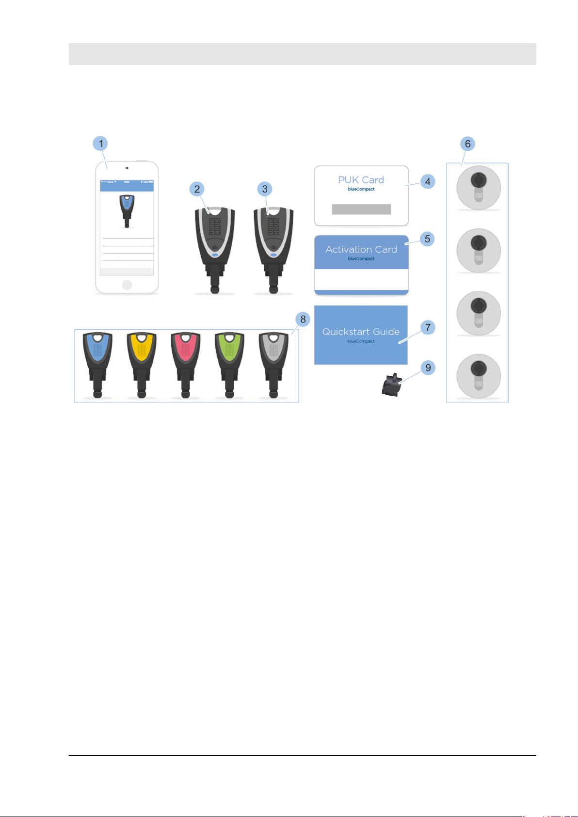
Fig. 3: System overview
1 Smartphone app
2 Master key
3 Active key
4 PUK card
5 Activation card
6 Cylinder
7 Quick start guide
8 Passive key
9 Adapter
30.06.2016 blueCompact Electronic locking system 13
Product overview
1.1 Compile components as required
The activation set is the basis for the locking system. Other
components must be purchased in addition to the set as
required.
The activation set contains the following components:
n Active key
–
Ä
Chapter 1.2.1 ‘Active keys’ on page 14
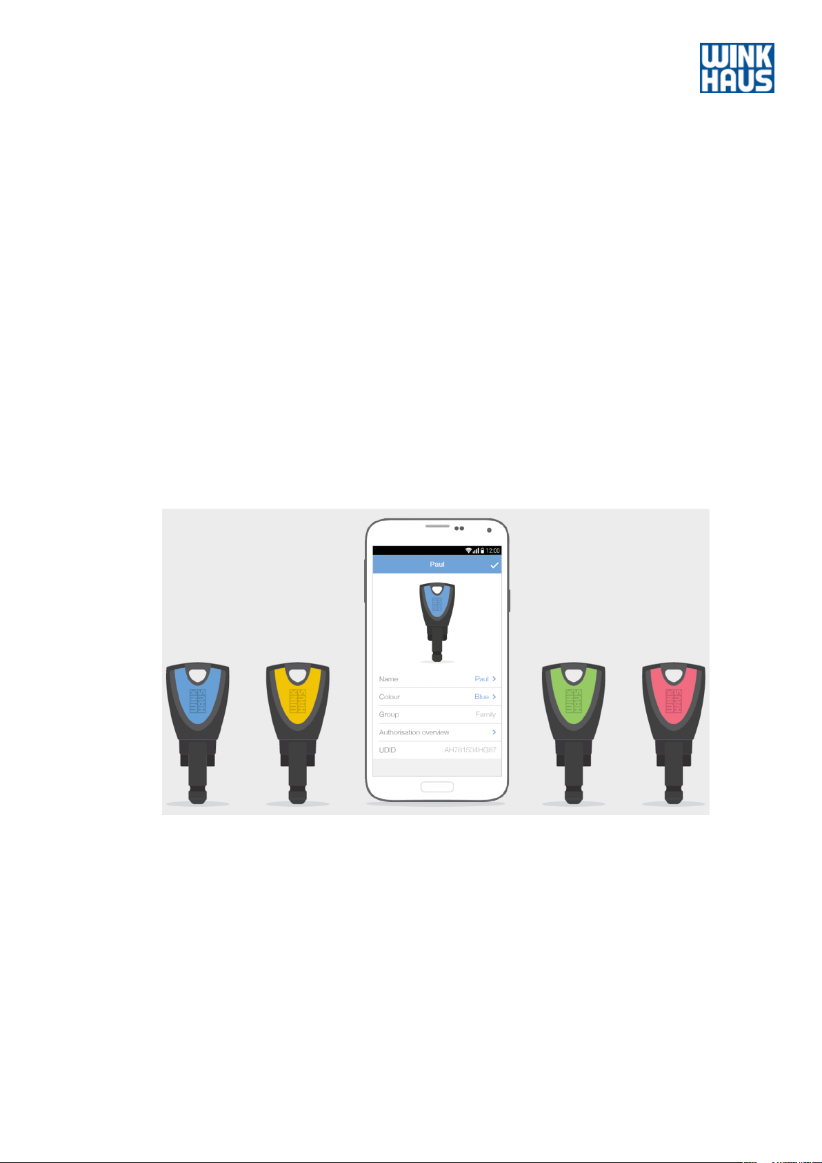
n 4 passive keys in different colours:
–
Ä
Chapter 1.2.3 ‘Passive key’ on page 19
– Green
– Pink
– Yellow
– Blue
n Activation card
Ä
Chapter 1.3 ‘Activation card’ on page 20
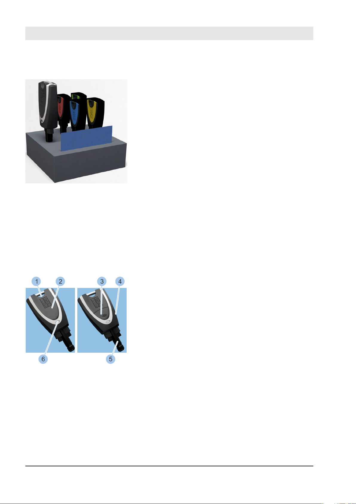
Fig. 4: Activation set
–
n PUK card
–
Ä
Chapter 1.4 ‘PUK card’ on page 20
n Adapter
Ä
Chapter 1.2.4 ‘Adapter’ on page 19
–
n Quick start guide
1.2 Key
1.2.1 Active keys
Fig. 5: Active key
1 Ring hole
2 Battery compartment cover
3 Button
4 Key bow
5 Tip of the key
6 LED display
Active keys feature a button (3) to activate cylinders, a
battery and a LED display (6). You can use the ring hole (1)
to fasten the key to a key ring.
An active key features the following functions:
n Lock cylinder.
–
Ä
Chapter 1.2.1.1 ‘Use user key function’ on page 16
n Lock cylinder with flat battery.
–
Ä
Chapter 1.2.1.2 ‘Use internal power function’
on page 17
n Read data from a passive key to lock cylinder with a flat
battery.
Ä
Chapter 1.2.1.3 ‘Use external power function’
–
on page 18
30.06.2016blueCompact Electronic locking system14
n Configuration as a master key.
–
Ä
Chapter 6.1 ‘Initialise master key’ on page 57
n Remote authorisation received.
–
Ä
Chapter 6.8 ‘Issue remote authorisation’
on page 79
You can read the battery charge status for all
components which have a battery.
–
Ä
Chapter 6.4.4 ‘Check the cylinder battery
charge status’ on page 68
The following battery statuses are displayed:
– Good
– Sufficient
– Low
– Replace
The battery must be replaced if the battery
charge status indicates 'low' or 'replace'.
Product overview
LED display signals
This signal warns of a low battery charge status in the
active key.
The signal is activated for the following functions:
n Internal power function if there is only enough power
for a few more locking transactions.
–
Ä
Chapter 1.2.1.2 ‘Use internal power function’
on page 17
n User key function if fewer than 1,000 locking transac-
tions are possible.
–
Ä
Chapter 1.2.1.1 ‘Use user key function’ on page 16
WARNING!
Hazard to persons due to malfunction in
emergency opening with an active key!
Replace the battery of the active key immediately
after this signal in order to avoid a situation where the
key does not lock the door in an emergency.
nÄ Chapter 9.2.1 ‘Replace the battery in an active
key.’ on page 98
This signal may indicate the following statuses:
n Active key has been activated using the button.
n Active key communicates with other components via
Bluetooth.
30.06.2016 blueCompact Electronic locking system 15
Product overview
LED display signals in power
adapter mode
1.2.1.1 Use user key function
The power adapter mode allows cylinders to be locked
using the internal power function and is activated by
pressing the button (2 seconds).
Ä
Chapter 1.2.1.2 ‘Use internal power function’ on page 17
This signal may indicate the following statuses:
n Search for a key which can be taught in.
n Search for a cylinder on which you can perform an
internal power locking transaction.
–
Ä
Chapter 1.2.1.2 ‘Use internal power function’
on page 17
Key has been taught in and is awaiting connection to cylinder.
Error in communication with a passive key or cylinder.
Repeat procedure.
Active key is authorised to lock.
Active key is not authorised to lock.
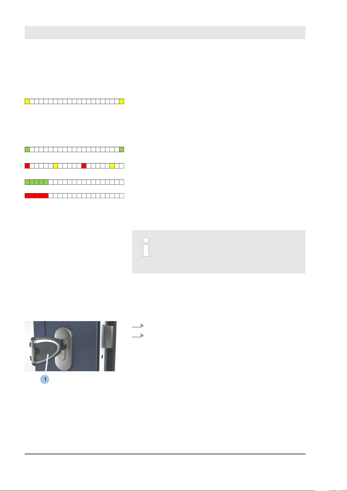
Lock the cylinder
Fig. 6: Lock the cylinder
An active key can be used in the same way as a
passive key (= user key). The button does not
need to be activated with the button to do so.
Ä
Chapter 1.2.3 ‘Passive key’ on page 19
Prerequisites:
n Battery is sufficiently charged.
n The active key features the corresponding locking
rights.
1. Insert active key (1) into the cylinder.
2. Lock cylinder.
30.06.2016blueCompact Electronic locking system16
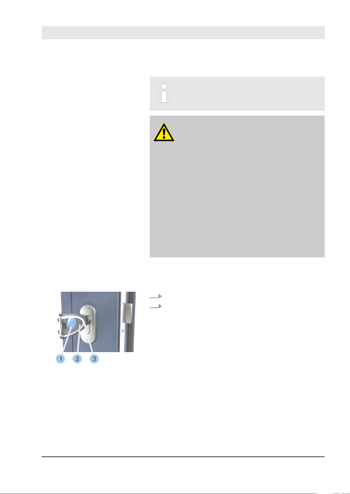
1.2.1.2 Use internal power function
Product overview
If the cylinder battery is flat, the lock can be
locked using the battery in an active key.
WARNING!
Hazard to persons due to malfunction in emer-
gency opening with an active key.
Active keys with a low battery charge status
may not be able lock cylinders with a depleted
battery.
– Check the battery charge status in all com-
ponents on a regular basis.
–
Ä
Chapter 6.4.4 ‘Check the cylinder bat-
tery charge status’ on page 68
– Immediately replace batteries with a low
charge level with new, approved batteries.
–
Ä
Chapter 9.2.1 ‘Replace the battery in an
Ä
active key.’ on page 98 –
9.2.6 ‘Replacing batteries in Padlock 85’
on page 107
–
Ä
Chapter 13 ‘Technical specifications’
on page 125
Chapter
Lock the cylinder
Fig. 7: Use internal power function
Precondition:
n The battery in the cylinder is flat.
1. Insert active key into the cylinder.
2. Activate active key by pressing the button (2) (for 2
seconds).
The LED display (3) on the active key lights up
ð
yellow and the lock can be locked using the power
in the battery (1) in the active key.
30.06.2016 blueCompact Electronic locking system 17
Product overview
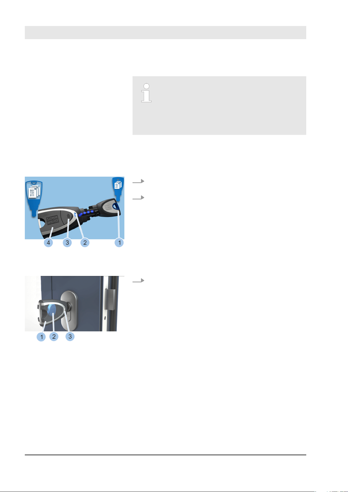
1.2.1.3 Use external power function
Read passive key
If the cylinder battery is flat, the lock can be
locked using the battery in an active key. If the
key has no battery (= passive key), the locking
authorisations in the passive key can be read
using an active key. This can then secure the lock
with the integrated battery within a period of
20 seconds.
Prerequisites:
n You have a passive key with locking authorisation.
n You have an active key with locking authorisation.
1. Activate active key (4) by pressing on the button (3)
(2 seconds).
2. Connect active key (4) with the passive key (1) using
adapter or manually.
The LED display (2) on the active key lights up
ð
yellow during the read process.
The locking authorisations in the passive key (1)
are read if the LED display (2) lights up green.
Fig. 8: Read passive key
Lock the cylinder
Fig. 9: Lock the cylinder
1.2.2 Master key
3. Insert active key (1) into the cylinder.
The LED display (3) on the active key (1) lights up
ð
yellow and the cylinder can be locked using the
power in the battery (2) in the active key (1) within
a period of 20 seconds.
The locking authorisation for the cylinder expires
after 20 seconds.
The master key is always an active key which you can configure as a master key using the app.
The master key features all the functions of an active key
and can also integrate active and passive keys and cylinders into the locking system. It can also identify them, read
information and display the battery status of any battery.
The master key holds all information about the locking
system in its memory. You can view this information in the
app.
30.06.2016blueCompact Electronic locking system18
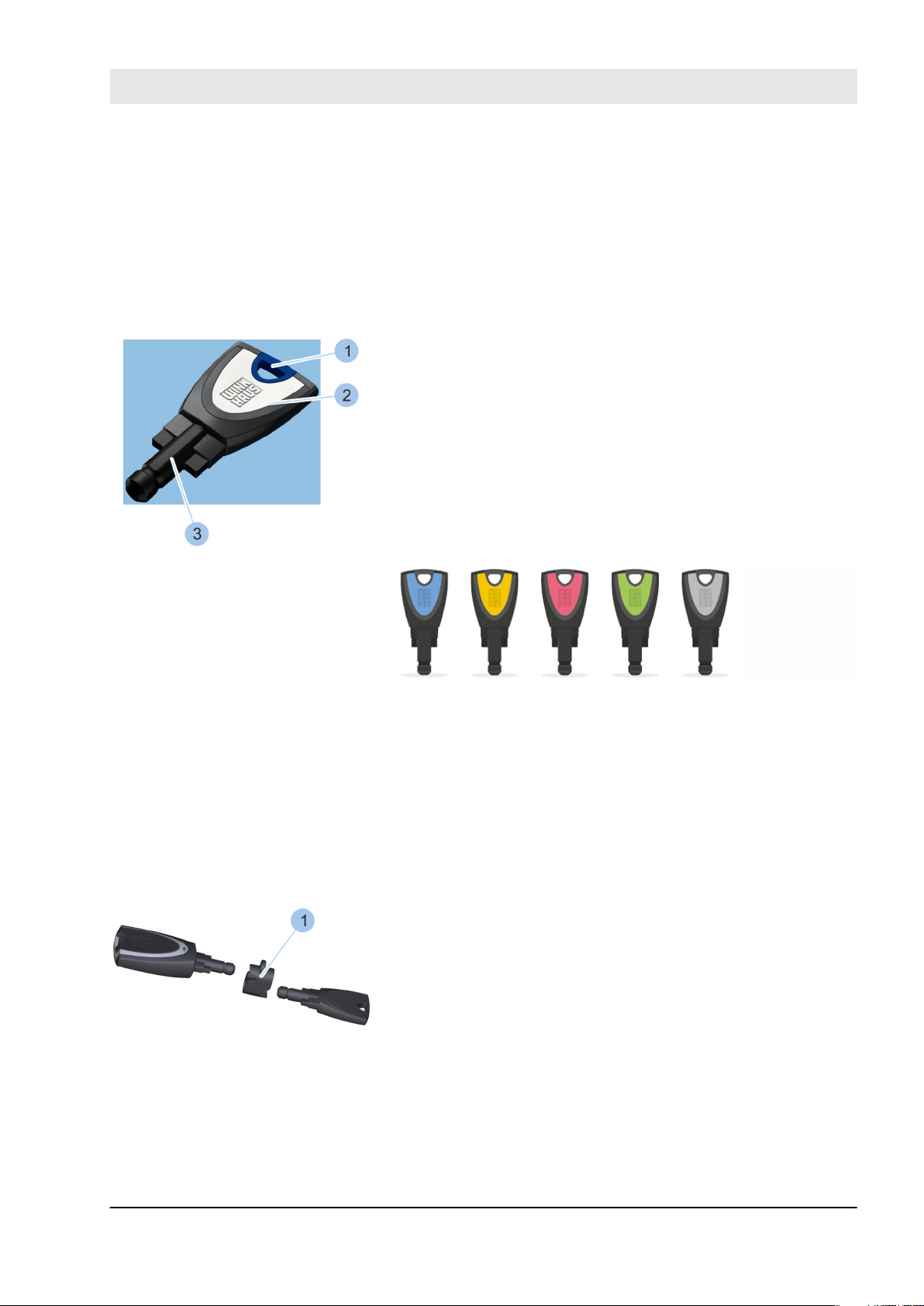
1.2.3 Passive key
Fig. 10: Passive key
Product overview
You may only configure one master key for each locking
system.
The master key logs off automatically after 2 minutes of
inactivity.
1 Ring hole
2 Key bow
3 Tip of key with transponder
You can use the master key to import passive keys into the
system and then manage them in the app.
A transponder is integrated into the tip of the key (3). This
transponder holds the locking authorisations for specific
cylinders. You can only use passive keys to lock cylinders
for which they have locking authorisations.
The key bows (1) in passive keys are colour-coded to make
it easier to manage the keys.
1.2.4 Adapter
Fig. 11: Adapter
The keys are available in the following 5 colours:
n Blue
n Yellow
n Pink
n Green
n Grey
The adapter (1) ensures that the keys are in the right position for data transfer. You can also hold the tips of keys
together for data transfer in your hand.
30.06.2016 blueCompact Electronic locking system 19
Product overview
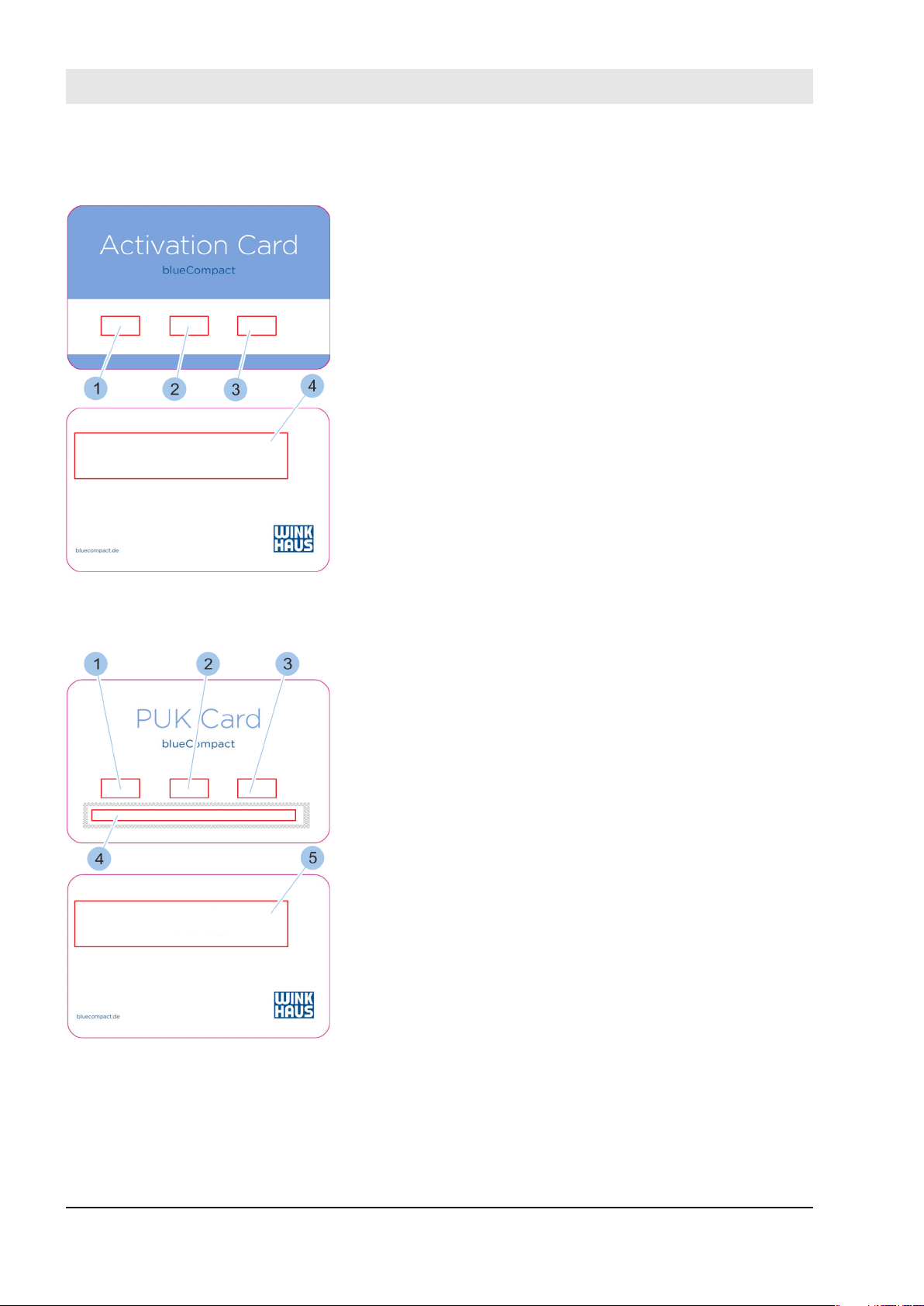
1.3 Activation card
1 System name
2 System
3 Card number
4 Instructions for safe storage
The activation card contains the required system data to
convert an active key into a master key for the locking
system.
The activation card contains the personal identification
number (PIN) to establish a Bluetooth link between the
master key and smartphone.
Fig. 12: Activation card
1.4 PUK card
1 System name
2 System
3 Card number
4 PUK code scratch-off panel
5 Instructions for safe storage
The PUK contains the personal unblocking code which you
can use if the password is lost.
Fig. 13: PUK card
30.06.2016blueCompact Electronic locking system20
1.5 Cylinder
Product overview
Different cylinder types can be integrated into the locking
system:
n Double cylinder
n Knob cylinder
n Half cylinder
n Padlock
The dimensions for individual cylinders are listed in the
technical specifications. You can increase the cylinder
length by 5-mm increments on one or both sides,
depending on the cylinder.
Ä
Chapter 13 ‘Technical specifications’ on page 125
You can read or display the battery charge
status for all cylinders.
–
Ä
Chapter 6.4.4 ‘Check the cylinder battery
charge status’ on page 68
The following battery statuses are displayed:
– Good
– Sufficient
– Low
– Replace
The battery must be replaced if the battery
charge status indicates 'low' or 'replace'. A cylinder will intentionally delay closing to indicate
an empty battery.
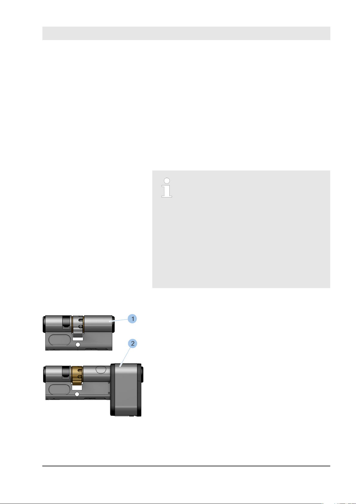
Double cylinder
Double cylinders can be closed on both sides.
The following double cylinders can be integrated into the
locking system:
n Type 01 (1) and Type 05 (1)
n Type 21 (2)
Type 01 (1) is used indoors for normal doors when the
doors must be locked electronically from both sides.
Type 05 (1) is used indoors for normal doors when the
doors must be only be locked electronically on the outside
(e.g. office doors). Unlike Type 01 (1), Type 05 (1) can be
locked mechanically from the inside.
Type 21 (2) is used indoors and outdoors for high usage
doors when the doors must be locked electronically from
Fig. 14: Type 01 and Type 21
30.06.2016 blueCompact Electronic locking system 21
both sides. The large battery compartment with large battery assure a long battery service life for high usage doors.
Product overview
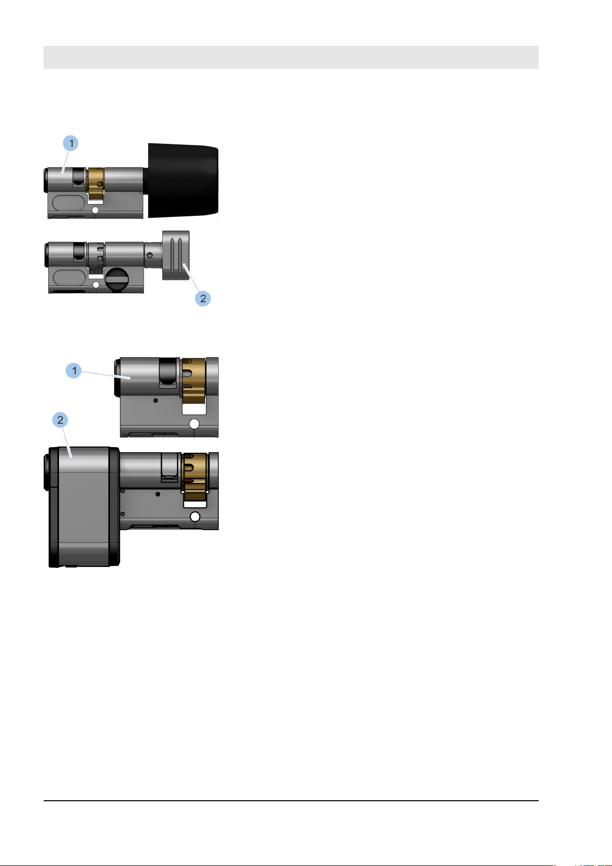
Knob cylinder
Fig. 15: Type 04 and Type 04 MK
Half cylinder
Knob cylinders can be locked on the outside using a key.
Knob cylinders have a knob on the inner side.
The following knob cylinders can be integrated into the
locking system:
n Type 04 (1)
n Type 04 MK (2)
The Type 04 (1) is used indoors for high usage doors that
are opened from the inside with a knob. The large battery
assures a long battery service life for high usage doors.
The Type 04 MK (2) is used indoors for normal doors that
are opened from the inside with a knob.
Half cylinders can be locked on one side only and fill half
the door only.
The following half cylinders can be integrated into the
locking system:
n Type 02 (1)
n Type 22 (2)
Fig. 16: Type 02 and Type 22
The Type 02 (1) is used indoors for key switches or lift
switches, etc.
The Type 22 (2) is used indoors and outdoors for high
usage doors of garden gates, etc. The large battery compartment with large battery assure a long battery service
life for high usage doors.
30.06.2016blueCompact Electronic locking system22

Padlock
Fig. 17: Type 85
Product overview
A padlock can be integrated into the locking system with
Type 85.
30.06.2016 blueCompact Electronic locking system 23

Product overview
30.06.2016blueCompact Electronic locking system24

2 Security
2.1 Intended use
Security
blueCompact is a locking system for private and commercial use. This locking system can be used to provide access
control and management for a maximum of 99 keys and 25
cylinders. The keys and cylinders are integrated into the
locking system using an app. You can use the app to query
battery charge statuses and code and manage keys and
cylinders.
The cylinders in the locking system are approved for use in
fire doors as per DIN EN 1634-1: T90 and must be tested to
DIN EN 1634-1: T90 by a chief fire officer of the local fire
brigade or an authorised expert. The cylinders must be
tested for use with emergency exit locking systems as per
DIN EN 179 or panic exit devices as per DIN EN 1125 must
be installed by a specialist company.
Misuse
WARNING!
Injury, damage and impairment of burglary
resistance due to improper usage.
Injury, damage and impairment of burglary
resistance may be caused if the components in
the locking system are used improperly.
– Do not fit cylinders in potentially explosive
atmospheres.
– Do not lock cylinders with damaged keys.
– Do not use a key to close a door or pull a
door open.
– Do not wash keys.
– Do not use keys as a lever.
– Do not throw keys.
– Do not use any tools to apply greater force
on the key when locking.
– Do not modify or alter any components in
the locking system without authorisation.
– Take operating conditions into account when
using in external doors.
– Do not insert any non-locking-system keys or
objects into the cylinder.
– Do not apply oil or grease to cylinders.
– Do not treat cylinders with graphite.
– Do not allow the cylinder to come into con-
tact with paint or thinner.
30.06.2016 blueCompact Electronic locking system 25
Security
2.2 Safety when installing cylinders in fire doors
Malfunctions in fire doors
WARNING!
Life-threatening hazard due to malfunctions in
fire doors.
Fire doors which do not function correctly may
result in death in hazardous situations.
– The cylinders are approved for use in fire
doors as per DIN EN 1634-1: T90. The chief
fire officer from the local fire service or an
authorised expert must carry out the final
inspection of the fire door, including the
installed cylinder.
– Match the cylinder to the requirements of
other components.
– Only a specialist company may incorporate
the cylinder into fire alarm system.
– Observe applicable guidelines and building
regulations regarding correct maintenance
and safety inspections. A record must be
made of the date, scope and results of
inspections and kept in a safe place.
2.3 Safety when installing cylinders in emergency doors
Malfunctions in emergency doors
WARNING!
Life-threatening hazard due to malfunctions in
emergency doors.
Emergency doors which do not function cor-
rectly may result in death in hazardous situations.
– Have cylinders installed into emergency
doors by a specialist company only.
– Check and install cylinder, lock, fitting and
mounting accessories as a unit for use in
emergency exit locking systems as per DIN
EN 179 or panic exit devices as per DIN EN
1125.
– Observe applicable guidelines and building
regulations regarding correct maintenance
and safety inspections. A record must be
made of the date, scope and results of
inspections and kept in a safe place. Take
into account inspections and inspection
periods as per technical approval for panic
locks.
30.06.2016blueCompact Electronic locking system26

Security
Anti-panic multi-point locking
systems
You may only fit a special anti-panic cylinder into antipanic multi-point locking systems with gear cases to ensure
that anti-panic doors are not blocked.
Contact Customer Service for more information.
Ä
‘Customer Service’ on page 3
2.4 Instructions on integrating alarm systems
Malfunctions in alarm systems
NOTICE!
Malfunctions in alarm systems when the locking
system is integrated incorrectly.
If the locking system is incorporated into the
higher level alarm system incorrectly, the alarm
system may malfunction.
– Only specialist companies may incorporate
the locking system into the alarm system.
2.5 The administrator's responsibilities
The locking system administrator manages the master key
and the PUK and activation cards. The administrator is
responsible for issuing locking rights.
The administrator is responsible for the following:
n Keeping the master key, PUK and activation cards in a
safe place.
n Issuing master key and PUK and activation cards to
authorised persons only.
n Instructing users in handling the locking system.
n Check battery charge statuses regularly depending on
the frequency of use of the individual components.
–
Ä
Chapter 6.4.4 ‘Check the cylinder battery charge
status’ on page 68
n Immediately replacing master key and activation card in
the event of loss.
Ä
Chapter 10.2 ‘Master key loss’ on page 112
–
–
Ä
Chapter 10.3 ‘Activation card loss’ on page 117
n Removing locking authorisations from the key con-
cerned immediately if individual keys are lost.
Ä
Chapter 6.4.5 ‘Issue and withdraw locking authori-
–
sations’ on page 69
30.06.2016 blueCompact Electronic locking system 27
Security
2.6 Hazards for people
Hazards caused by batteries
n Disposing of batteries in the correct manner.
–
Ä
Chapter 12 ‘Disposal’ on page 123
n Ensuring functions are tested and maintenance carried
out correctly in the case of fire and emergency doors.
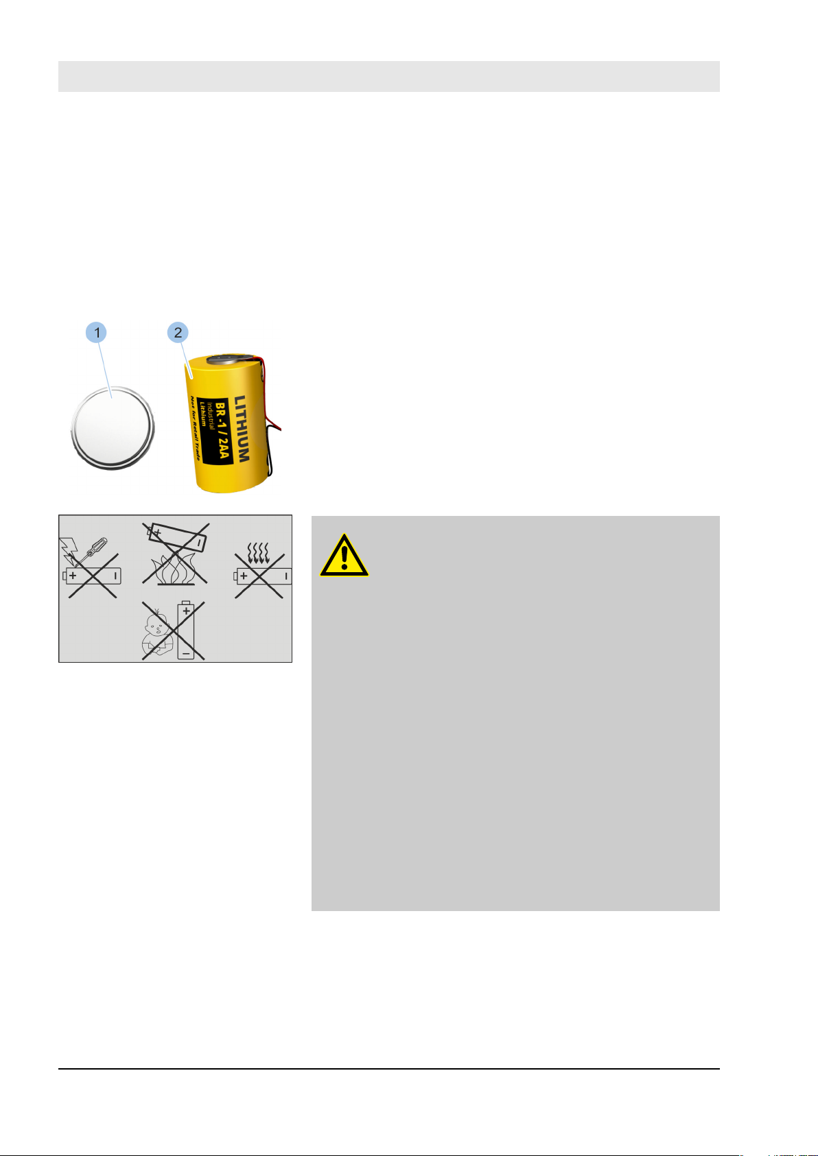
Button cells (1) (CR2032 and CR1220) and 1/2AA batteries
(2) are installed in the components in the locking system.
Batteries contain toxic heavy metals. They are subject to
special waste treatment and must be disposed of at municipal collection centres or by a specialised company.
Ä
Chapter 12 ‘Disposal’ on page 123
WARNING!
Risk of injury from improper handling of bat-
teries.
Improper battery handling poses the risk of the
batteries exploding or leaking out hazardous liquids. This liquid may cause irritation upon contact with the skin, severe poisoning if swallowed
and blindness upon contact with the eyes.
– Only use batteries with poles in the correct
position (+/-).
– Never use force to insert batteries.
– Never heat batteries over 85 °C.
– Never use, charge or store batteries in loca-
tions with explosive atmospheres or where
high temperatures may emerge.
– Keep batteries away from unauthorised per-
sons and small children at all times.
– Never subject batteries to strong vibrations,
heavy weights or other damaging effects to
ensure that you prevent fire, overheating,
explosions or leaks. Leaking battery fluid
may catch fire.
30.06.2016blueCompact Electronic locking system28
Hazards due to low battery
charge status
Security
WARNING!
Hazard to persons due to malfunction in emer-
gency opening with an active key.
Active keys with a low battery charge status
may not be able lock cylinders with a depleted
battery.
– Check the battery charge status in all com-
ponents on a regular basis.
–
Ä
Chapter 6.4.4 ‘Check the cylinder bat-
tery charge status’ on page 68
– Immediately replace batteries with a low
charge level with new, approved batteries.
–
Ä
Chapter 9.2.1 ‘Replace the battery in an
Ä
active key.’ on page 98 –
9.2.6 ‘Replacing batteries in Padlock 85’
on page 107
–
Ä
Chapter 13 ‘Technical specifications’
on page 125
Chapter
Hazards due to swallowing
2.7 Risk to property
WARNING!
Hazards due to swallowing.
It is possible to swallow small component parts
in the locking system or the battery replacement
set, which can lead to death due to choking.
Swallowing batteries can lead to serious injury.
– Keep locking system components and the
battery replacement set safely out of children's reach.
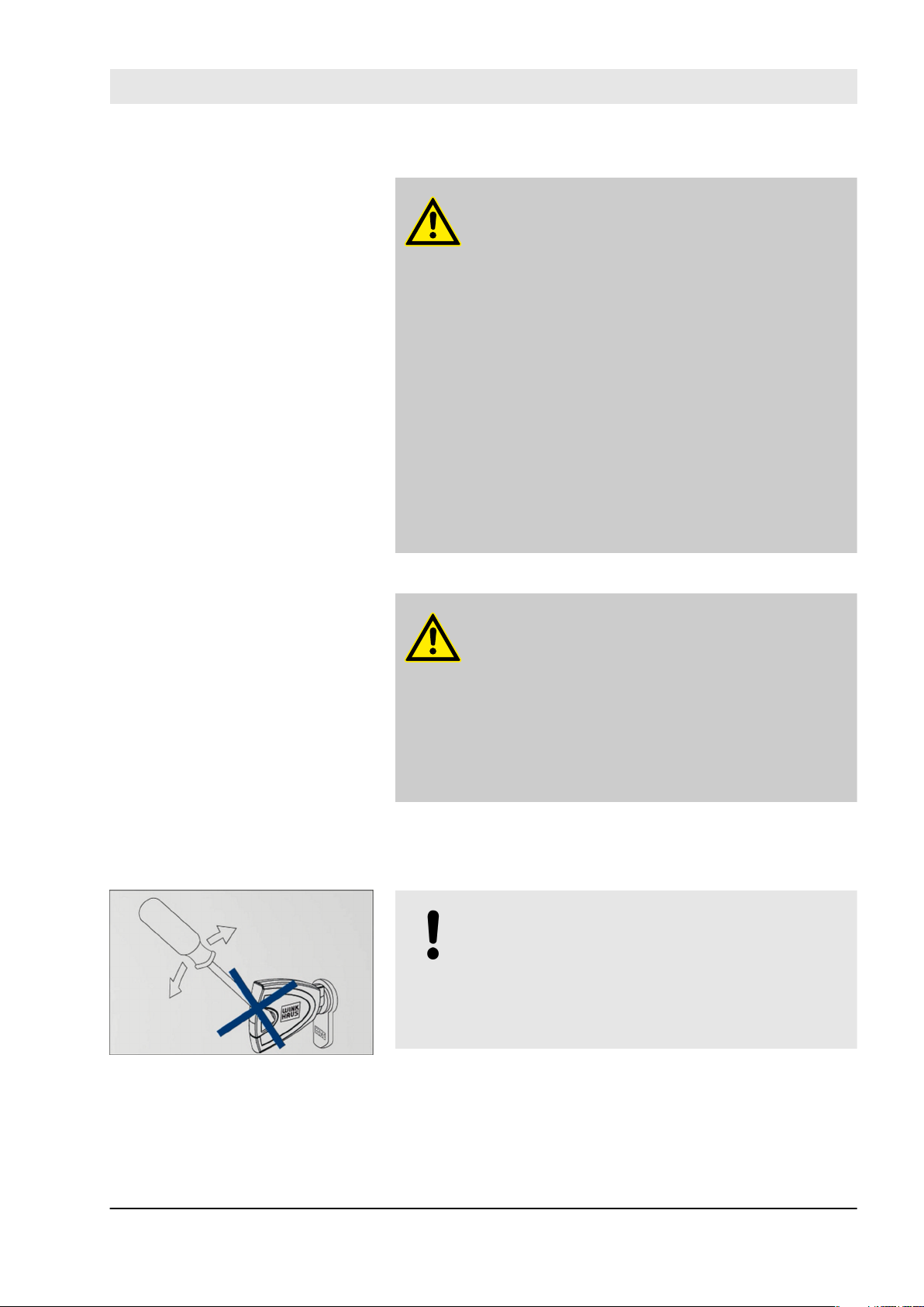
NOTICE!
Damage caused by using tools which increase
force when locking the cylinder.
Using tools which increase force can break off
the key and damage the cylinder.
– Turn the key by hand only when locking.
30.06.2016 blueCompact Electronic locking system 29
Security
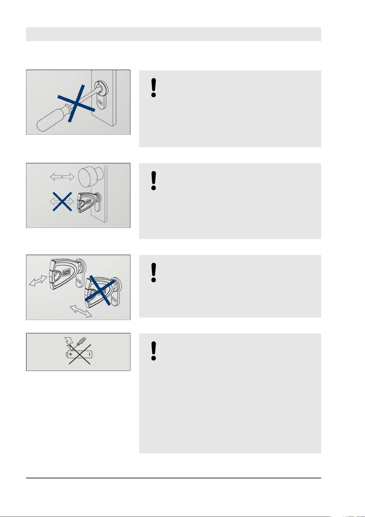
NOTICE!
Damage caused by tools or other objects
inserted into the keyway.
Trying to lock the cylinder using tools or other
objects can cause damage to the cylinder.
– Lock with authorised keys only.
– Do not insert any tools or other objects into
the cylinder.
NOTICE!
Damage caused by pulling the door open with
the key.
The key may break if doors are pulled closed
with the key. Broken pieces of the key may
block the keyway.
– Use the door handle or knob to open and
close unlocked doors.
NOTICE!
Damage caused by pulling out keys incorrectly.
You may deform or break off the key if you twist
the key while taking it out of the cylinder.
– Always pull the key out of the cylinder in a
straight line.
NOTICE!
Damage caused by damaged batteries.
Damaged and/or non-approved batteries can
damage the components in the locking system
and cause malfunctions.
– Never short circuit the batteries’ contacts
(positive and negative terminal).
– Never expose the batteries to wet or mois-
ture (rain, salt water, liquids). Never use wet
or damp batteries.
– Never attempt to solder, repair, reshape,
convert or disassemble batteries.
– Use the batteries contained in the battery
replacement set only.
30.06.2016blueCompact Electronic locking system30
 Loading...