

Winity Technology WGM100 Users Manual

MK00001
Pluto
GSM-GPRS M
odem User Guide
Pluto
GSM-G
PRS
M
ode
m U
se
r Guide
Ver
s
ion:
1.06 HW-debug
-
board
-1.1
20
th
2007
M
K00001
CONFIDENTIAL PAGE: 1
/34 Subject to
NDA
Mar
T
his PRELIMINARY document contains information
on a product under continual development and is
issued for evaluation purpose only
. All inf
ormation is
MK00001
Pluto
GSM-GPRS M
odem User Guide
Department: Marketing
© Winity Technology Inc. 2007.
All other
copyright and trade-marks are acknowledged.
HISTORY
Note:
1. 2. 3. 4. 5. The first release.
CONFIDENTIAL PAGE: 2
/34 Subject to
NDA
nd
th
th
th
Originator Approval
Name Techih Chen
Date 2-25-2007
Signature
Version
Date Author Approval Note
1.01
2
5
March 07
7
March 07
8
March 07
th
20
March 07
March 07
AC
TP RC 2
TC
AC
AC
1.02
1.03
1.04
1.05
1.06
Replaced GPRS Modem install guide
Added SLM connector pin-outs
Removed text multiple version numbers; added note on ‘access point node’.
Added volume level AT command info
1
3
4
5
T
his PRELIMINARY document contains information
on a product under continual development and is
issued for evaluation purpose only
. All inf
ormation is

MK00001
Pluto
GSM-GPRS M
odem User Guide
CONTENTS
1.
Objective
4
5 5 6
9 10 15 17 18 19 20 21 26 27 27 28
29 30 31 32 34 34 34 CONFIDENTIAL PAGE: 3 /34 Subject to
NDA
2.
References
3.
Important Notices
4.
Introduction
4.1
4.2
4.3
5.
6.
7.
8.
8.1
8.2
8.3
8.4
8.5
8.6
8.7
8.8
8.9
8.10
8.11
8.12
9.
9.1
9.2
9.3
9.4
9.5
9.6
9.7
Overview
Description of Hardware
Operating the SLM-GG
Features
Interfaces
Specifications
Notebook/PC Installation
Add a new modem
Installing the CCww Modem Driver
Checking Modem Connection
Configuring Port Speed
Initialization Commands
Data Connection Preferences
Hardware Settings
Configuring Dial-Up Connection
Connection Properties
Modem Configuration
PPP Settings
TCP/IP Settings
Examples of at command
Initialization
SMS Configuration
SMS (PDU) Mode
How to Send and receive Short Message
Setting or query configuration information command
MT or MO Call
Get Current Network ID
29
4
4
5
7
7
8
9
T
his PRELIMINARY document contains information
on a product under continual development and is
issued for evaluation purpose only
. All inf
ormation is

MK00001
Pluto
GSM-GPRS M
odem User Guide
1. Obje
ctive
This document describes the Pluto GSM-GPRS modem features, interfaces, and specifications. It includes
The s
uppliers take no res
ponsibility for m
odem
operation unless these guidelines are correctly followed. If in
2. Ref
eren
ces
AT-command Set (us_ds.pdf)
3.
Important Notices
s
-
2. CONFIDENTIAL PAGE: 4
/34 Subject to
NDA
the installation procedure for Microsoft Windows XP-based notebooks and PCs. Normal modem interaction is
achieved through a notebook/PC dial-in, to access the AT-command set via a serial link, e.g. for access to the
internet or dialing a call.
Note that GSM-only users should ignore all references to GPRS functionally and features.
doubt, please refer to your supplier.
[1] CCWW/UG/103:
[2] SLM-MB_User_Manual_V1.0.3: Pluto_MB_Modem_User_Manual
1.
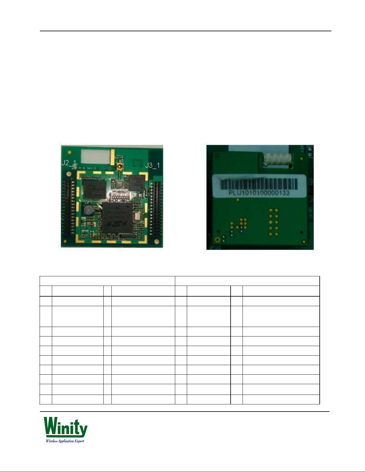
Damage to the RF power-amp may occur if the modem is powered-up without a suitable antenna, or the antenna i
disconnected whilst the modem is powered. Note the modem may be supplied with an in-built helix antenna (right
hand picture in 4.2 below) or with a connector (left-hand picture) for an external antenna.
If the modem is being correctly operated, and yet does not provide a connection to the internet from your PC,
please check your PC fire-wall settings.
T
his PRELIMINARY document contains information
on a product under continual development and is
issued for evaluation purpose only
. All inf
ormation is
MK00001
Pluto
GSM-GPRS M
odem User Guide
4. Int
rodu
ct
ion
4.1 Overview
The Pluto (Single-chip Terminal ARchitecture) GSM-GPRS Modem provides a high-performance, innovative, flexib
l
4.2 Description o
f Hardware
n
CONFIDENTIAL PAGE: 5
/34 Subject to
NDA
and comprehensive platform that uses the Silicon Laboratories' AeroFONE™ 4904 device, providing the
most cost-effective and best time-to-market solution for terminal developers creating GSM-GPRS modem-based
products.
The Pluto GSM-GPRS Modem (SLM-GG) is a self-contained modem with an AT-command interface. It is show
below:
SLM-GG uses a SMD-type connector to plug into a mother-board with the following pin configuration:
J2_1 J3_1
PIN
NAME I/O Description
NO.
1 KEYIN0 I
2
KEYOUT0
3 KEYIN1 I
4 KEYOUT1 O
5 KEYIN2 I
6 KEYOUT2 O
7 KEYIN3 I
8 KEYOUT3 O
9 SYSRST# O
10 KEYOUT4 O
Keypad input 1
O
Keypad Output
Keypad input 3
Keypad Output 4
Keypad input 5
Keypad Output 6
Keypad input 7
Keypad Output 8
System Reset
Output(Active
Keypad Output 10 NRESET#
PIN
NAME I/O Description
NO.
VBATT I Battery Voltage
Batter
2
VBATT
VBATT I Battery Voltage
GND P
GND P
GPIO5 I/O General Purpose I/O
GPIO2/EXTBOOT I/O General Purpose I/O/External Boot
GPIO38/I2C_SCL I GPSR Clock
9 GPIO3 I/O General Purpose I/O
I
y
Voltag
e
Power GND
Power GND
T
his PRELIMINARY document contains information
on a product under continual development and is
issued for evaluation purpose only
. All inf
ormation is
MK00001
Pluto
GSM-GPRS M
odem User Guide
SLM-GG is supplied with its GSM-GPRS pr
otocol stack
and drivers installed, r
eady
to use. It suppo
rts a standa
rd
For eval
uation and onward development, SLM-GG is supplied with a m
other-
board (SLM-MB), a mains-powered
4.3 Operating the SLM-GG
1. Type AT into the noteboo
k/PC AT-comm
and window; the m
odem
will reply with ‘OK
CONFIDENTIAL PAGE: 6
/34 Subject to NDA
11 BATT_THERMISTOR I Battery Temperature Detection 11 GPIO6 I/O General Purpose I/O
12 KEYOUT5 O
EAR_OUTN/HEADSET_
13
R
14 GND P
EAR_OUTP/HEADSET_
15
L
16 UART1_TD O
17 GND P
18 UART1_CTS I
19 HSO_OUTP O
20 UART1_RTS O
21 HSO_OUTN O
22 UART1_RD I
23 VCM_OUT O
24 AUX_PONKEY I
25 LINEOUT_P O
26 HEADSET_MIC I
27 LINEOUT_N O
28 INTMIC_P I
29 GND P
30 SYSCLK_OUT O
31 VCHG I
32 GND P
33 VCHG I
34 VCHG I
Keypad Output 12 GPIO39/I2C_SDA I/O GPSR I/O
O Headset Output R-CH 13 GPIO57/SIM_PRES I SIM Present? Input
Power GND 14 GPIO49/SSI_OUT O SSI Serial Data
O Headset Output L-CH 15 SIM_RST O
Transmitted data 16 GPIO50/SSI_DATA I/O SSI Rx and Tx Data
Power GND 17 SIM_DIO I/O Data I/O for SIM card
Clear to send 18 GPIO48/SSI_CLK O SSI Serial Data Clock
Receiver Output(+) 19 SIM_CLK I SIM clock output
Reques to send 20 GPIO51/SSI_SEL0 O SSI Serial Select Line Output
Receiver Output(-) 21 PWM1 O
Received data 22 PWM0 O
Headset Common Mode
Output
Aux Power On
Key(System
Line Driver Output(+) 25 UART0_RI O
External(Headset)Microphone
Input
Line Driver Output(-) 27 UART0_RD O
Voice Band Microphone Input 28 UART0_TD I
Power GND 29 UART0_DSR O
32KHz or System Clock
Output
Charger voltage input 31 UART0_CTS O
Power GND 32 GPIO8 I/O General Purpose I/O
Charger voltage input 33 VSIM
Charger voltage input 34 VBAT_RTC I RTC battery voltage input(coin cell)
23 GND P
24 UART0_DCD O
26 UART0_RTS I Request to send
30 UART0_DTR I Data terminal ready
Active low reset output for SIM card
PWM Out-Vibrator
PWM Out-Backlight
Power GND
Data Camier Detect Output
Ring Indicator
Received data to external device
Transmitted data from external
device
Data set ready
Clear to send
VDD SIM
set of AT-commands, described in CCWW/UG/103 with examples given in Ch.8 of this guide.
DC supply, and 2 UART cables for connection to notebook/PC. Please refer to the Pluto Modem Mother
Board User-Manual [2] for further information.
SLM-GG can be used in conjunction with a customer’s own mother board, or with CCasia’s mother board (SLM-MB)
described in [2], supplied with the Pluto Modem Evaluation Kit (SLM-EVK).
When the modem is powered up:
2. Follow operations described in Ch.7 and see also examples in CH.8 in this guide.
T
his PRELIMINARY document contains information
on a product under continual development and is
issued for evaluation purpose only
. All inf
ormation is

MK00001
Pluto
GSM-GPRS M
odem User Guide
3. Always type ‘AT+CPWROFF’
and await the res
ponse: ‘
Now Safe to Switch off’ before switching off
the power
supply.
•
AT+CLVL=<n> where n is an integer
from 1 to
10; 10 is max volume 5. Please report any problems with the installation
and operation to y
our s
upplier, who will expect a report to
•
• •
A de
scription of operations l
eading up to the problem
5. Feat
ures
Pr
ocessor
RTOS
Q
uad B
and
GPRS
•
• •
Class 12, Class B
Key
pads
Audio
•
• • • •
S
peech c
odec: HR/FR/EFR/AMR
SMS
Interfaces
Peri
pheral interf
aces
CONFIDENTIAL PAGE: 7 /34 Subject to
NDA
4. Use the following command to adjust handset volume:
contain:
Information from the notebook/PC configuration
Transaction history from the notebook/PC (and where appropriate, jHAT log-file)
Single chip solution
•
ARM9 156MHz
•
Nucleus Plus for ARM9
•
E- GSM 900 and DCS 1800
•
GSM850 and PCS 1900
Coding scheme CS1 to CS4
Nucleus NET and PPP
•
5 x 5
Echo Cancellation + noise reduction
Microphone (not supplied)
Hand free Speaker (not supplied)
Earphone (not supplied)
•
Support Text and PDU mode
6.
SIM Interface
•
1.8V/2.8V SIM interface
•
4-wire SPI
•
2 UART – Maximum baud rate up to 115.2Kbps
T
his PRELIMINARY document contains information
on a product under continual development and is
issued for evaluation purpose only
. All inf
ormation is

MK00001
Pluto
GSM-GPRS M
odem User Guide
•
• •
I2C – Maximum r
ate up to 400kbps
2PWM – Vibrator and LCD backlight control
•
• • • •
GPIO: For
Code
Downl
oad
•
•
Reset Pin
Specificat
ions
7. Transmit Power
Power Supply
C
onnec
tor
Ant
enna
R
eal time Cl
ock JTAG interface for development M
odem
Module
•
Overall dimensions:
CONFIDENTIAL PAGE: 8 /34 Subject to
NDA
5 G PIOs:
GPIO: For Audio Amp shutdown control.
GPIO: For customer use
GPIO: For memory power setting
GPIO: For customer use
Power On Pin
13 MHz or 32.768KHz output
•
Class 4
(2W@850/900MHz)
•
Operating voltage 3.6 ~ 4.5V, Typical 3.9V
•
Battery charge management is included
•
60pins, Dual 2 x 17 female header pitch 1.27mm
•
RF connector
40 x 40 x 3.3 mm (without antenna)
40 x 40 x 6.5 mm (with supplied helix antenna)
T
his PRELIMINARY document contains information
on a product under continual development and is
issued for evaluation purpose only
. All inf
ormation is
MK00001
Pluto
GSM-GPRS M
odem User Guide
8. Not
eboo
k/
PC
Installa
t
ion
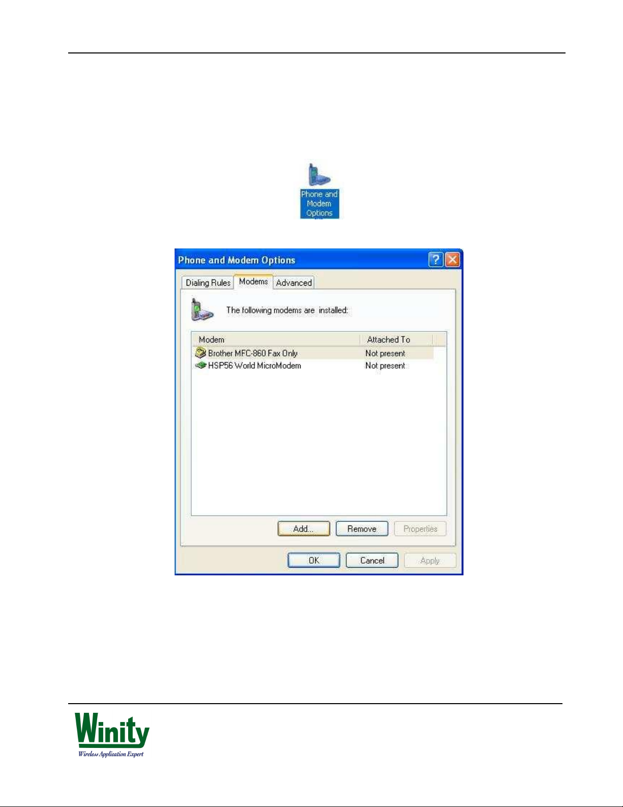
8.1 Add a new modem
Navigate to Control Panel (usually accessible from the Start Menu) and Open 'Phone and Modem Options'.
On the following Dialogue
box click 'A
dd...' to begin the ‘
add new hardware’ wizard. CONFIDENTIAL PAGE: 9 /34 Subject to
NDA
T
his PRELIMINARY document contains information
on a product under continual development and is
issued for evaluation purpose only
. All inf
ormation is
MK00001
Pluto
GSM-GPRS M
odem User Guide
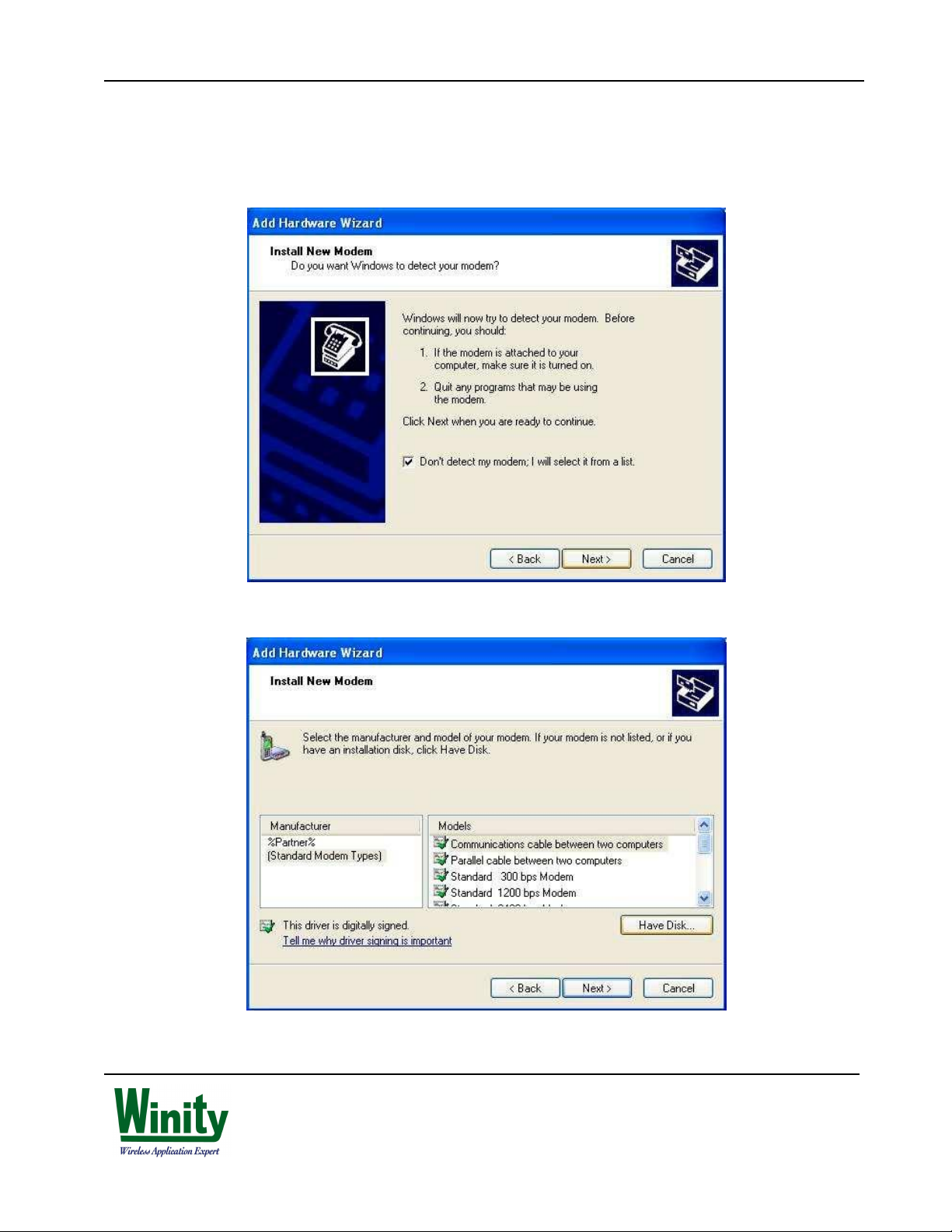
8.2 Installi
ng the CCww Modem Driver
On the first screen of the wizard check the tick box next to 'Don't detect my modem; I will select it from a list' and
CONFIDENTIAL PAGE: 10 /34 Subject to
NDA
click 'Next >'.
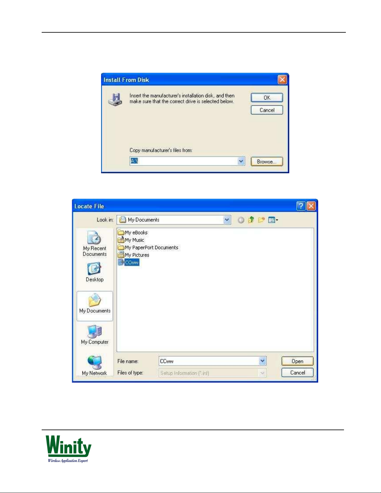
In the following dialogue box click 'Have Disk...'.
T
his PRELIMINARY document contains information
on a product under continual development and is
issued for evaluation purpose only
. All inf
ormation is
MK0000
1
Pluto
GSM-GPRS M
odem User Guide
If you know the location of
the driver file (Ccww.inf) you can
enter
it in
the text box below. Alter
natively click
'Browse...'.
Clicking 'Browse..' in
the above will open
up a ‘Locate File’ dialogue
box allowing you to m
anua
lly search the file
CONFIDENTIAL PAGE: 11
/34 Subject to
NDA
system. Upon locating the file click 'Open'.
T
his PRELIMINARY document contains information
on a product under continual development and is
issued for evaluation purpose only
. All inf
ormation is
 Loading...