

Page 1

LCD TELEVISION
INSTRUCTION MANUAL
DLN-15D3SHS
DLN-17D3SHS
DLN-20D3AHS
Page 2
IMPORTANT
INFORMATION
FCC RF INTERFERENCE STATEMENT
NOTE : This equipment has been tested and found to comply with the limit for a Class B digital device,
pursuant to Part 15 of the FCC Rules. These limits are designed to provide reasonable protection
against harmful interference in a residential installation.
This equipment generates, uses and can radiate radio frequency energy and, if not installed and
used in accordance with the instructions, may cause harmful interference to radio communications.
However, there is no guarantee that interference will not occur in a particular installation.
If these equipment does cause harmful interference to radio or television reception which can be
determined by turning the equipment off and on, the user is encouraged to try to correct the
interference by one or more of the following measure.
• Reorient or relocate the receiving antenna.
• Increase the separation between the equipment and receiver.
• Correct the equipment into an outlet on a circuit different from that to which the receiver is
connected.
• Consult the dealer or an experienced radio, TV technical for help.
• Only shielded interface cable should be used.
2
CAUTION
RISK OF ELECTRIC SHOCK
DO NOT OPEN
CAUTION : TO REDUCE THE RISK OF ELECTRIC SHOCK,
DO NOT REMOVE COVER (OR BACK)
NO USER-SERVICEABLE PARTS INSIDE.
REFER SERVICING TO QUALIFIED SERVICE PERSONNEL.
The lightning flash with arrowhead symbol, within an equilateral triangle, is
intended to alert the user to the presence of uninsulated “dangerous voltage” within the product’s enclosure that may be of sufficient magnitude to constitute a risk
electric shock.
The exclamation point within an equilateral triangle is intended to alert the user to
the presence of important operating and servicing instructions in the literature
accompanying the appliance.
Page 3

IMPORTANT
INFORMATION
WARNING : FCC regulations state that any unauthorized changes or modifications to this equipment not
expressly approved by the manufacturer could void the user’s authority to operate this
equipment. U.S.A. ONLY
Note to CATV system installer : This reminder is provided to call the CATV system installer’s attention to
Article 820-40 of the National Electrical Code that provides guidelines for
proper grounding and, in particular, specifies that the cable ground shall
be connected to the grounding system of the building, as close to the point
of cable entry as practical.
This product utilizes tin-lead solder, and fluorescent lamp containing a small amount of mercury.
Disposal of these materials may be regulated due to environmental considerations. For disposal or
recycling information, please contact your local authorities or the Electronic Industries Alliance :
www.eia.org
3
Page 4
SAFETY
PRECAUTIONS
The present set has been designed and manufactured to
assure personal safety. Improper use can result in electric
shock or fire hazard. The safeguards incorporated in the
present unit will protect you if you observe the following
procedures in installing, using and servicing. The present
unit is fully transistorized and does not contain any
element that can be repaired by the user.
• Read these instructions : All functional instructions must
be read and understood before operating the product.
• Keep these instructions : It is recommended to keep
these safety guidelines and operating instructions in a
safe place for future reference.
• Heed all warnings : All warnings on the product and in
the instructions must be observed closely.
• Follow all instructions : All operating instructions must
be followed.
• Attachments / Accessories : Only use the attachments /
accessories specified by the manufacturer. Using
inadequate attachments can result in accidents.
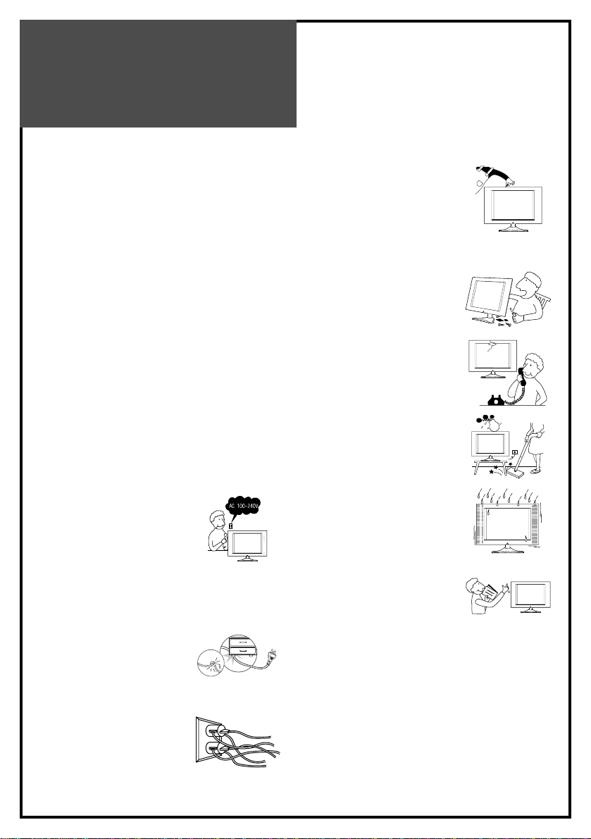
• Power source :This product must
operate according to the power
source indicated on the
specification label. If you are not
sure of the type of power supply
used in your home, consult your
dealer or local electric company. For the units designed
to operate on batteries or another power source, refer to
the operating instructions.
• Power cord protection : Protect
the power cord from being
walked on or pinched particularly
at plugs, convenience receptacles,
and the point where they exit from
the apparatus.
• Overloading : Do not overload
AC outlets or extension cords.
Overloading can cause fire or
electric shock.
• Influx of objects and liquids :
Never let objects into the
productthrough vents or openings.
Due to the high voltage flows in the
product, inserting a foreign object
in the product can cause electric
shock and/or shorten internal elements. For the same
reason, be careful not to spill water or other liquids over
the product.
• Servicing : Do not attempt to service
the product yourself. Removing
covers can expose you to high
voltage and other dangerous
conditions. Request a qualified
service person to perform servicing.
• Repair : Unplug the AC cord from
the outlet, and request a qualified
service person to perform repairs
when:
a. The power cord or plug is
damaged.
b. A liquid is spilled on or an object is
dropped into the product.
c. The product has been exposed to
rain or water.
d. The product does not function
properly as described in the
operating instructions. Do not touch
the controls other than those
described in the operating
instructions. Improper adjustment
of controls out of the instructions
can cause damage, which often requires a qualified
technician for extensive adjustments.
e. The product has been dropped or damaged.
f. The product displays an abnormal condition. Any
noticeable abnormality in the product indicates that the
product needs servicing.
4
Page 5
SAFETY
PRECAUTIONS
• Replacement parts : In case the
product needs certain parts to be
replaced, make sure that the service
engineer uses the replacement
elements either specified by the
manufacturer, or with the same
characteristics and performance as original ones. Using
unauthorized parts can result in fire, electric shock
and/or other danger.
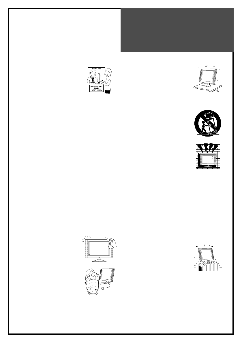
• Safety checks :Upon completion of service or repair
work, request the service technician to perform safety
checks to ensure that the product is in proper operating
condition.
• Polarization : Do not defeat the safety purpose of the
polarized or grounding type plug. A polarized plug has
two blades with one wider than the other. A grounding
type plug has two blades and a third grounding prong.
The wide blade or the third prong is provided for your
safety. When the provided plug does not fit into your
outlet, consult an electrician for replacement of the
obsolete outlet.
Caution : To prevent electric shock, match wide blade of
plug to wide slot, fully insert.
Attention : Pour éviter les choc électriques, introluire la
lame la plus large de la fiche dans la borne
correspondante De la prise et pousser jusqu’au
pond.
• Cleaning : Unplug the AC cord
from the AC outlet before cleaning
the product. Use only with a dry
cloth to clean this apparatus. Do
not use liquid or aerosol cleaners.
• Water and moisture : Do not use
this product near water such as
bathtub, washbasin, kitchen sink
and laundry tub, swimming pool
and in a wet basement. TV set shall
not be exposed to dripping or
slashing and no objects filled with liquids, such as vases,
shall be placed on the TV set.
• Stand : Do not place the product on
an unstable cart, stand, tripod or
table. Unstable installation is likely
to make the product fall resulting in
serious injuries as well as material
damage. Use only the cart, stand,
tripod, bracket, or table specified by the manufacturer,
or sold with the apparatus.
• When a cart is used, use caution
when moving the cart / apparatus
combination to avoid injury from
tip-over.
• Ventilation : The vents and other
openings in the cabinet are
designed for ventilation. Do not
cover or block them since
insufficient ventilation can overheat
and/or shorten the product ’s life
span. Do not place the product on the bed, sofa, rug or
other similar surfaces since they can block ventilation
openings. This product is not designed for built-in
installation; do not place the product in an enclosed
place such as a bookcase or rack unless proper
ventilation is provided or the manufacturer ’s instructions
are followed.
• The LCD panel used in this product is made of glass.
Therefore, it can be broken when the product is dropped
or gets shock. Be careful not to be injured by glass
pieces in case the panel is broken.
• Heat sources :Do not install near
any heat sources such as radiators,
heat registers, stoves, or other
apparatus (including amplifiers)
that produce heat.
• The LCD panel is a product of very high technology with
2,359,296 (15 ”)/ 2,949,120 (17” Wide) thin film
transistors, giving you fine picture details. Occasionally,
a few non-active pixels may appear on the screen as a
fixed blue, green or red point . Please note that this does
not affect your product ’s performance.
5
Page 6
SAFETY
PRECAUTIONS
6
• As a measure of additional
protection of this television
equipment, unplug this apparatus
during lightning storms or when
unused for long periods of time.
This will prevent the equipment
from being damaged by lightning and power-line
surges.
• Outside antenna system should not be located in the
vicinity of overhead power lines or other electric or
power circuits including the place where it can fall onto
such power lines or circuits. Installing outside antenna
system requires a full care to keep such power lines or
circuits out of reach as it may be fatal to touch them.
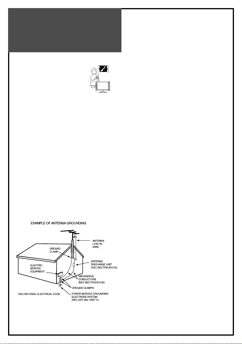
• If an outside antenna is connected to television
equipment, be sure the antenna system is grounded so
as to provide some protection against voltage surges
and built-up static charges.
Section 810 of the National Electrical Code provides
information concerning proper grounding of the mast
and supporting structure as well as of the lead-in wire to
an antenna discharge unit, the size of grounding
conductors, the location of antenna-discharge unit, the
connection to grounding electrodes and the requirements
for grounding electrode.
Page 7

CONTENTS
7
IMPORTANT SAFEGUARDS 5
SUPPLIED ACCESSORIES 6
FUNCTIONAL OVERVIEW 7
Front (Control panel) 7
Remote controller 8
PREPARATION 9
Inserting Batteries into the Remote Control Unit 9
Mains connection 9
Aerial connection 10
Connecting external equipment 12
INSTALLATION 15
Language selection 15
Automatic Tuning of TV Channels 15
Programme Editing 16
Manual Setup 17
DAILY USE 18
Switching On and Off 18
Recall 18
Programme Selection 19
Picture Control 19
Sound Control 20
Special Features 21
Sleep 21
Teletext (Option) 22
PC setup 24
WALL/ARM MOUNTING 26
TROUBLESHOOTING 27
PRODUCT SPECIFICATIONS 28
Page 8
Supplied
Accessories
8
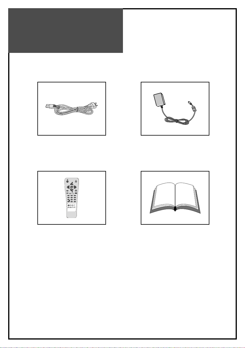
AC cord AC adapter
123
456
789
RECALL
SLEEP
PC
POWER
VOL VOL
PR
PR
NORMAL
S.MODEASPECT
X
?
MENU
0
Remote controller Instruction manual
Page 9

Functional
Overview
Front (Control panel)
9
Remote
sensor
LED
indicator
STAND-BY
ON/OFF CH VOL
TV/VIDEO
MENU
Power
On/OffCHUp/Down
Volume
Up/Down
AV MENU
Page 10

Functional
Overview
Remote Controller
[ ] : Teletext function
10
123
456
789
PICTURE
MODE
SOUND
MODE
DISPLAY MTS
TV
AV
COMPONENT
PC
POWER
MUTE
VOL VOL
CH
CH
PREV. CH
CAPTION
SLEEP
TV/CABLEADD/DEL
ASPECT
MENU
0100
MUTE MUTE
MENU
CH UP
LEFT(VOLUME DOWN)
RIGHT(VOLUME UP)
CH DOWN
PREV. CH
ASPECT
SLEEP
DISPLAY
NUMBER(PAGE)
PICTURE MODE
SOUND MODE
ADD/DEL
AV/CABLE
Page 11
Preparation
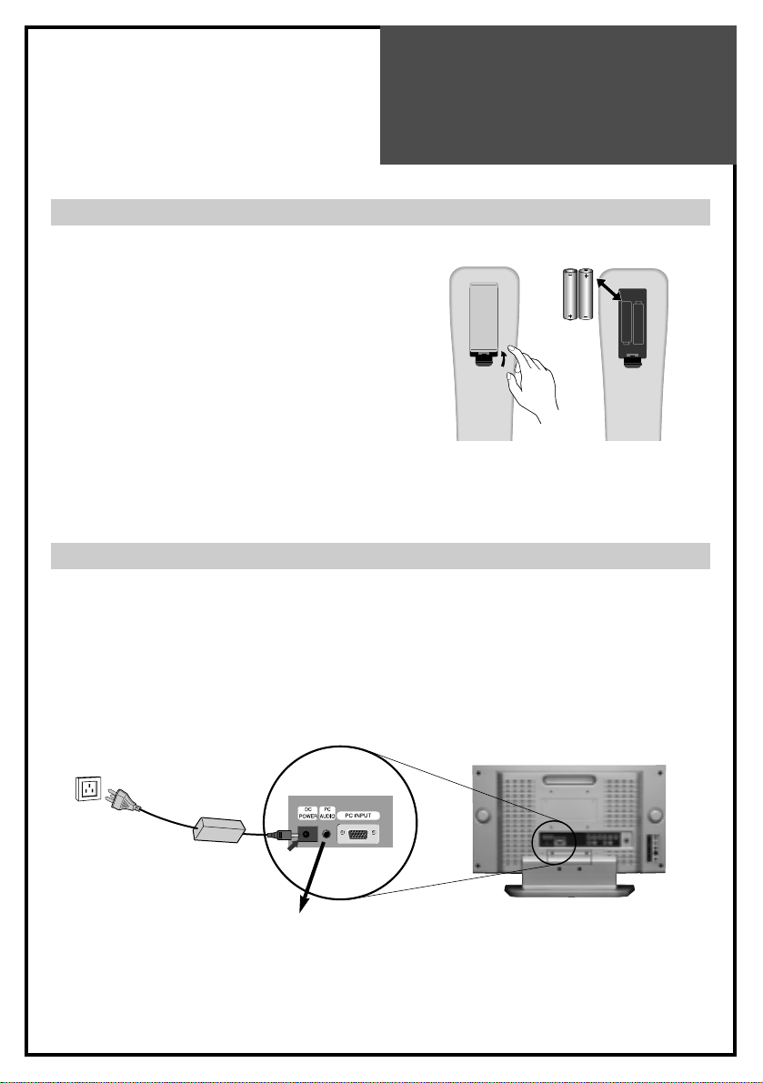
Inserting Batteries into the Remote Control Unit
Mains Connection
1. Connect the DC plug of the AC adaptor to the DC 12V(DC 15V-only 20”) input terminal of
the set.
2. Connect the AC adaptor and AC cord.
3. Plug the other end of AC cord into a Power outlet with 100V - 240V AC, 50/60Hz.
11
To load the batteries, turn the remote control
handset over and open the battery compartment.
Insert the batteries (Not supplied, two 1.5v, type
R03 or AAA). Make sure that the polarity
matches with the (+) and (-) marks inside of the
battery compartment.
Note: To avoid damage from possible battery
leakage, remove the batteries if you do not
plan to use the remote control handset for
an extended period of time.
Power outlet
AC Adapter
AC Cord
DC 12V input terminal
(DC 20V-only 20”)
Page 12

Connections
ANTENNA CONNECTION
TO CABLE TV (CATV)
• A 75-ohm coaxial cable connector is built into the set for easy hookup. When connecting the
75-ohm coaxial cable to the set, screw the 75-ohm cable to the ANT. terminal.
• Some cable TV companies offer “premium pay channels”. Since the signals of these premium
pay channels are likely to be scrambled, a cable TV converter/descrambler is generally
provided to the subscriber by the cable TV company. This converter/descrambler is
necessary to watch scrambled channels normally. (Set your TV to channel 3 or 4 as one of
them is generally used. If the channel is unknown, consult your cable TV company.) For more
specific instructions on installing cable TV, consult your cable TV company. On the next
page, a possible using method of the converter/descrambler provided by your cable TV
company is explained. Please note: an RF switch provided with two inputs ( A and B ) is
required (not supplied).
12
Cable TV
Converter/Descrambler
Two-set signal
SPLITTER
RF Switch
Incoming cable
Page 13

Connections
TO WALL ANTENNA SOCKET
If there is a wall antenna socket in apartment house, connect the antenna cable as shown
below. (Use the type of antenna cable corresponding to that of wall antenna socket.)
For good quality of image, the antenna requirements of color television reception are more
strict than those of black & white television reception. Thus, it is strongly recommended to use
good outdoor antenna.
The following is a brief explanation of the type of connections that are provided with the
various antenna systems.
1. A 75-ohm system is generally a round cable with F-type connector that can be easily
attached to a terminal without tools (not supplied).
2. A 300-ohm system is a flat “twin-lead” cable that can be attached to a 75-ohm terminal
through a 300-75-ohm antenna converter (not supplied).
• If you have a 75-ohm round cable, insert bronze wire and then tighten connecting nut. If you
have a 300-ohm flat cable, connect twisted wire to antenna converter and then connect the
converter to ANT IN.
• When using 75-ohm round cable, do not bend bronze. It may cause poor picture quality.
13
Wall connecting port
75 round cable
300 flat cable
Antenna
converter
Turn clockwise
to tighten
Page 14

Connections
TO OUTDOOR ANTENNA
This type of antenna is usually used at common private house.
• Use one of the two following diagrams if you connect an outdoor antenna.
A : Using a VHF/UHF combination outdoor antenna.
B : Using separate VHF and/or UHF outdoor antennas.
• Connect the outdoor antenna cable lead-in to the ANT IN on the back of TV set.
• In a poor signal area, you can get better picture quality if you install the antenna like the
figure “B”.
• If an antenna is divided to two TV sets, use “signal divider” for connection.
14
Combination
VHF/UHF Antenna
75
round cable
300
flat cable
Turn clockwise
to tighten
Antenna
converter
Signal
Amplifier
UHF
VHF
Page 15
Connections
15
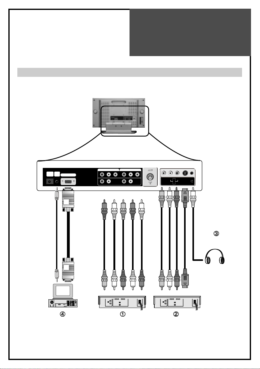
Connecting external equipment
PC INPUT
Pr Pb Y R L
PC
AUDIO
DC
POWER
VIDEO
AUDIO
L
R
S-VIDEO
Pr PbRLY
COMPONENT 2
Pr PbRLY
COMPONENT 1
PC DVD
DTV Set Top Box
Headphone
S-video cable
VCR/Camcorder/
Video Game
Page 16

Connections
16
You can enjoy picture and sound by connecting VCR, DVD player (or DTV Set-Top Box) and
PC to the terminals located on the back of TV set. Before connecting an external device, turn the
TV set off to avoid any possible damage.
DVD or DTV Set-Top Box input terminal [COMPONENT IN]
These jacks have Y/Pb(Cb)/Pr(Cr) inputs and AUDIO inputs.
These jacks are used to connect a DVD player, DTV Set-Top Box. (Available input mode :
480i, 480p, 720p, 1080i)
External AV devices input terminal [AV IN]
These jacks have VIDEO/AUDIO/S-VIDEO inputs. Connect them to VCR, Camcorder or
Video game with RCA or S-VIDEO cable.
* If your AV device has both VIDEO OUT terminal and S-VIDEO OUT terminal, S-VIDEO
connection is recommended for better picture quality.
• VIDEO and S-VIDEO in AV IN share the same jack with AUDIO input. Thus, they can’t be
used at the same time.
• Whenever you connect external equipment system to TV, make sure that all elements are
switched off. Refer to the documentation supplied with your equipment for detailed
connection instructions and associated safety precautions.
Headphone Jack
Insert the headphone plug (3.5mmØ) into this jack. The sound from the speaker will be
automatically cut off. You can control the headphone sound with Volume Up/Down (
)
buttons.
* Headphones are not included in the supplied accessories.
PC In
Connect the D-sub 15 pin cable and the audio cable with personal computer.
* See page 24 for more information of PC mode.
Page 17

Basic
Operations
17
TV/AV MODE SELECTION
By pressing the TV/VIDEO button on the TV set,
you can
change the mode as follows:
TV AV S-Video Comp1 Comp2
PC TV ....
With the remote controller, you can select the
mode as below.
• TV button : Selection for TV input mode.
• AV button : Selection for AV/S-Video input
mode.
• PC button : Selection for PC monitor input
mode.
• COMPONENT button : Selection for
Component input mode.
SWITCHING ON/OFF
SWITCHING ON
1 If the indicator is not lit, the TV set is powered off. You must press the POWER button of
the TV set.
2 Press the POWER button on the remote controller on the TV set when the indicator is red.
The TV set will be switched on and the indicator will be changed to green.
SWITCHING OFF
1 To set the TV set back to stand-by mode, press the POWER button on the remote
controller on the TV set for 2 seconds. The indicator will become red.
2 Press the POWER button on the TV set to switch the TV set off completely.
* If you turn the TV off, the present time that you have set will disappear.
• If you don't use the set for extended periods of time, unplug the AC cord from power
outlet.
TVAVPC
COMPONENT
Page 18
Basic
Operations
18
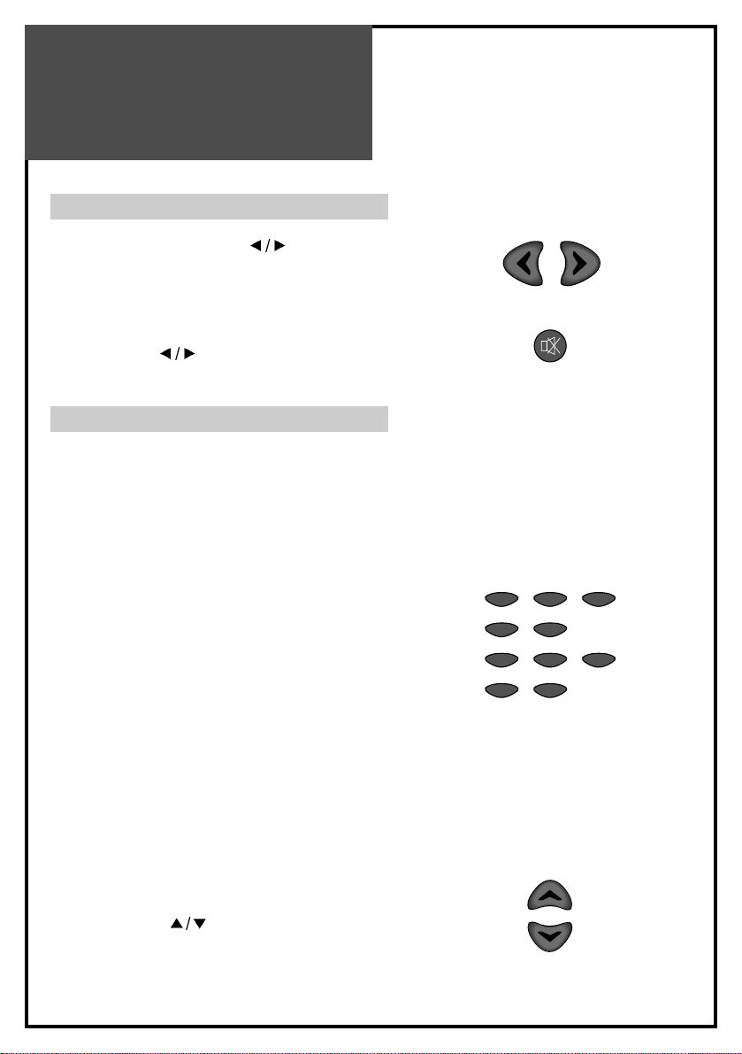
VOLUME CONTROL
Adjust the volume with VOL ( ) buttons.
TO MUTE THE SOUND
Press the MUTE button on the remote controller to
cut the sound off. By pressing either the MUTE
button or VOL (
) buttons, you can get sound
back.
CHANNEL SELECTION
The TV set has 68 channels [AIR02 ~ AIR69] in
AIR mode and 125 channels [CATV01 ~
CATV125] in CATV mode. (Refer to next page for
each selection.)
DIRECT SELECTION
The numeric buttons are used for direct channel
selection. To select two-digit channels, press the
second number button within 2 seconds after the
first number.
To select 3-digit channels, press ‘+100’ button
before pressing the rest of number buttons in
order.
• Channel number in green : Memorized
channels by automatic search or added
channels by user.
Channel number in white : Skipped channels by
automatic search or deleted channels by user.
UP/DOWN SELECTION
You can also select a memorized channel by
pressing the CH (
) buttons.
VOL VOL
MUTE
123
45
789
0100
CH
CH
Page 19

1919
CHANNEL ADJUSTMENT(ONLY IN TV MODE)
Press MENU button to display the MENU screen.
Press VOL up(
) button to enter into the items below.
The color of selected items becomes blue.
AIR/CABLE SELECTION
1 Move to “AIR/CABLE” by pressing CH (
)
buttons.
2 Press VOL (
) buttons to select either AIR or
CABLE which is appropriate to your antenna system.
CHANNEL AUTO SEARCH
CHANNEL AUTO SEARCH function memorizes all the
channels which are being received at real time. Before
operating this function, select one between AIR and
CABLE.
1 Move to “AUTO SEARCH” by pressing CH (
)
buttons.
2 Press VOL up (
) button to operate the searching.
Wait until the searching ends.
CURRENT CHANNEL NUMBER SELECTION
1 Move to “CURRENT CHANNEL” by pressing CH (
) buttons.
2 Press VOL (
) buttons to select a current channel
number you want.
ADD OR DELETE CHANNEL
You can add additional channels or erase unwanted
channels from TV memory.
1 Move to “CURRENT CHANNEL” by pressing CH (
) buttons and select desired channel.
2 By pressing VOL (
) buttons, select ADD for
adding the current channel to the TV’s memory or
select DEL for erasing the channel from the TV’s
memory.
3 Exit with MENU button. The change is stored.
• To interrupt AUTO SEARCH, press
MENU button. SEARCH will stop at
the current channel and will not add
any higher channels.
Picture
air / cable air cable
auto search
channel 10
add / del add del
Sound
Utilities
Channel
Move Select Exit
M
ATS
10 %
exit
M
Menu
Adjustment
Page 20

Menu
Adjustment
20
PICTURE ADJUSTMENT
Press MENU button to display the MENU screen.
Select “PICTURE” by pressing VOL (
) buttons and
press CH down (
) button to enter into below items.
CONTRAST
1 Move to “CONTRAST” by pressing CH (
) buttons.
2 Press VOL (
) buttons to adjust the picture contrast.
BRIGHTNESS
1 Move to “BRIGHTNESS” by pressing CH (
)
buttons.
2 Press VOL (
) buttons to adjust picture brightness.
COLOR
1 Move to “COLOR” by pressing CH (
) buttons.
2 Press VOL (
) buttons to adjust color intensity.
TINT
1 Move to “TINT” by pressing CH (
) buttons.
2 Press VOL (
) buttons to adjust skin color to a more
natural tone.
SHARPNESS
1 Move to “SHARPNESS” by pressing CH (
)
buttons.
2 Press VOL (
) buttons to adjust picture sharpness.
Picture
Mode Standard
Brightness 32
Contrast 32
Color 32
Tint 0
Sharpness 32
Sound
Utilities
Channel
Move Adjust Prev.
M
For less contrast For more contrast
For less brightness For more brightness
For less color intensity For less color intensity
Skin tones become purplish Skin tones become greenish
For less sharpness For more sharpness
• For PC or COMPONENT mode
(except 480i mode), only
“CONTRAST” and “BRIGHTNESS”
can be selected.
Page 21

Menu
Adjustment
21
SOUND ADJUSTMENT
Press MENU button to display the MENU screen.
Select “SOUND” by pressing VOL (
) buttons, then
press CH down (
) button to enter into the items
below.
TREBLE
To stress high frequency sound
1 Move to “TREBLE” by pressing CH (
) buttons.
2 Press VOL (
) buttons to adjust the treble
weaker or stronger.
BASS
1 Move to “BASS” by pressing CH (
) buttons.
2 Press VOL (
) buttons to adjust the bass
weaker or stronger.
BALANCE
1 Move to “BALANCE” by pressing CH (
)
buttons.
2 Press VOL (
) buttons to adjust audio output
between left and right speakers.
SPATIAL
This function is to work virtual surround sound effect.
1 Move to “SPATIAL” by pressing CH (
)
buttons.
2 Press VOL (
) buttons to select.
SUPER BASS
1 Move to “SUPER BASS” by pressing CH (
)
buttons.
2 Press VOL (
) buttons to select.
Picture
Balance 0
Bass 0
Treble 0
Spatial on off
Super bass
on off
Mts
mono stereo sap
Sound
Utilities
Setup
Move Adjust Prev.
M
For weaker treble For stronger treble
For weaker bass For stronger bass
Decrease right
speaker sound
Decrease left
speaker sound
• When “MONO” mode is selected, the
sound remains mono even if the TV set
receives a stereo broadcast. You must
switch the mode to “STEREO” if you
want to hear stereo sound.
• If you get some strange sound on
stereo mode in poor signal area or
non-dual signal service area, make
sure to select MONO mode.
Page 22

Menu
Adjustment
22
Daily Use
PC ADJUSTMENT (ONLY IN PC MODE)
PC Mode input format.
Please up-grade the video card driver with the latest version because some of old version video
cards may not support the 1280x768 resolution.
In case of inputting the PC signal other than above signals, “OUT OF RANGE” will appear on
the screen.
Standard Resolution(Mode) V-frequency(Hz) H-frequency(Hz) 15” 17” 20”
MAC 640x480 66 35.00 O O O
832x624 75 49.73 O O O
IBM 640x480 60 31.47 O O O
720x400 70 31.47 O O O
VESA 640x480(VGA) 72 37.86 O O O
800x600(SVGA) 60 37.88 O O O
72 48.08 O O O
1024x768(XGA) 60 48.37 O O X
70 56.48 O O X
1280x768(WXGA) 60 47.70 X O X
Page 23

Menu
Adjustment
23
Daily Use
Before adjustment, please setup your PC
software...
Even if your actual display-settings screen looks
different from the windows below, basic setup
methods will be applied in most of the cases.
1 First, click on “Settings” on the Windows Start
menu. While “Settings” is selected, move the
cursor to submenu “Control Panel”.
2 When the control panel screen appears, click
on “Display” and a display dialog box will
appear.
3 Navigate to the “Settings” tab on the display
dialog-box. The correct setting of size
(resolution) is “1024 x 768 pixels”. (optical
resolution) Check the vertical frequency of your
PC. (Available vertical frequency at 1024*768
mode : 60Hz, 70Hz, 75Hz)
Page 24

Menu
Adjustment
24
Press MENU button to display the MENU screen.
Select “PC” by pressing VOL (
) buttons and
press CH down (
) button to enter into the items
below.
H-POSITION
1 Move to “H-POSITION” by pressing CH (
)
buttons.
2 Press VOL (
) buttons to adjust the
horizontal position of displayed image.
V-POSITION
1 Move to “V-POSITION” by pressing CH (
)
buttons.
2 Press VOL (
) buttons to adjust the vertical
position of displayed image.
PHASE
(Fine image adjustment in PC monitor mode)
1 Move to “PHASE” by pressing CH (
)
buttons.
2 Press VOL (
) buttons to adjust the phase to
get a clearer picture.
Picture
H position 100
V position 0
Phase 11
Frequency 0
Auto setup
Sound
Utilities
Screen
Move Adjust Prev.
M
before adjustment after adjustment
before adjustment after adjustment
Page 25

25
Wall/Arm
Mounting
Attaching a Wall or Arm mounting device
This TV supports the VESA mounting standard
and willaccommodate various VESA mounting
devices.
To install any VESA mounting device, please
follow the manufacturer’s instructions.
1. Remove all cables connected to the TV.
2. Lay the LCD TV face-down on a flat surface
with ablanket or other soft materials to protect
the screen.
3. Remove the four screws attaching the stand.
Remove stand from LCD TV.
4. Remove the four screws attaching the VESA.
5. Now you are ready to install the VESA
mounting device suited to your applications
(see instructions below).
6. Connect all cables removed at step 1.
Installing VESA compliant mounting devices
1. Align the mounting interface pad (100mm x
100mm hole spacing) with the holes in the
televisions rear cover mounting pad.
2. Secure bracket with the four screws (4mmØ)
that came with the VESA mounting device.
Page 26
SPECIFICATION
26
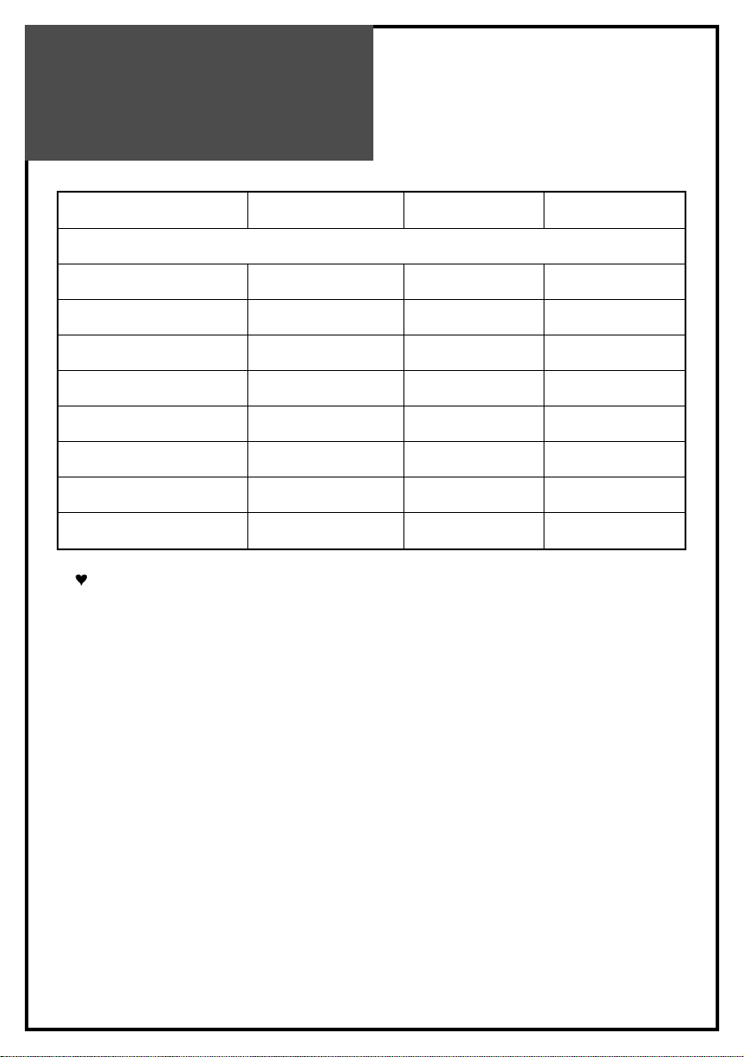
Owing to out policy of continuous improvement, specifications may change.
MODEL NUMBER DLN-15D3SHS DLN-17D3SHS DLN-20D3AHS
POWER REQUIREMENT AC 100V-240V~, 50/60Hz
POWER CONSUMPTION34W40W50W
APPEARANCE(mm) 463x345x215 544x358x215 608x456x215
WEIGHT 6Kg 7Kg 11Kg
SCREEN SIZE 381mm 434.38mm 510.54mm
ASPECT RATIO 4:3 16:9 4:3
NUMBER OF PIXELS 1024x768 1280x768 800x600
DISPLAY COLOR 16.2M 16.2M 8bit 16.7M 8bit
PIXEL PITCH 0.3(H)x0.3(V) 0.29(H)x0.29(V) 0.51(H)x0.51(V)
 Loading...