

Rev PA1
CDMA1900 Dual Band Selective Repeater
0.5W
User Manual

Rev PA1
CDMA1900 Dual Band Selective Repeater
0.5W
User Manual
© Ericsson AB 2009
All rights reserved. The information in this document is the
property of Ericsson. Except as specifically authorized in writing
by Ericsson, the receiver of this document shall keep the
information contained herein confidential and shall protect the
same in whole or in part from disclosure and dissemination to
third parties. Disclosure and disseminations to the receiver's
employees shall only be made on a strict need to know basis. The
information in this document is subject to change without notice
and Ericsson assumes no responsibility for factual inaccuracies or
typographical errors.

Contents
1 Preface......................................................................................................1
2 System Summary .................................................................................... 2
2.1 Overview....................................................................................................2
2.2 Brief Introduction ....................................................................................... 2
2.3 Basic Working Principle.............................................................................2
2.4 Product Features....................................................................................... 3
2.5 Case Variants............................................................................................ 3
2.6 Interface.....................................................................................................4
3 System Structure.....................................................................................5
3.1 System Constitution...................................................................................5
3.2 DL/UL LNA ................................................................................................ 5
3.3 DL/UL Band Selective Unit........................................................................5
3.4 DL/UL PA...................................................................................................5
3.5 Coupler for Modem....................................................................................5
3.6 Modem.......................................................................................................5
3.7 Control Unit................................................................................................6
3.8 Duplexer....................................................................................................6
3.9 Power Supply ............................................................................................ 6
4 Instruction for antenna selection...........................................................7
4.1 Applicable MPE Limits...............................................................................8
4.2 FCC Formulas and Calculations................................................................8
4.3 Selection for Service Antennas ................................................................. 9
5 System Commissioning........................................................................11
5.1 Testing Tools and Instruments................................................................11
5.2 VSWR Test of Antenna and Feeder System...........................................11
5.3 Voltage Test of Power Supply System....................................................11
5.4 Parameter Test........................................................................................11
5.5 Remote Control Test ............................................................................... 12

CDMA1900 Dual Band Selective Repeater 0.5W
1 Preface
Manual Instruction
CDMA1900 Dual Band Selective Repeater 0.5W is an important part of the CDMA
network system. It mainly receives processes and amplifies RF signal to extend the
BTS coverage area.
This manual introduces the working principle, function, structure and commissioning
of the Dual Band Selective Repeater.
Content Introduction
This user manual mainly introduces four chapters including working principle,
function, structure, commission.
Chapter 2: System brief introduction mainly introduces the basic working principle,
product characteristics and interfaces etc...
Chapter 3: System structure introduces the use of every unit in the Band selective
repeater such as main modules, monitoring units and PA units… which will make
the user have a good knowledge of the Band selective repeater structure.
Chapter 4: System instruction for antenna selection, The equipment does meet the
exemption requirements in respect of RF Exposure… Applicable MPE Limits, FCC
Formulas and Calculations, Selection for Service Antennas.
Chapter 5: System commissioning mainly introduces the general testing procedures
of the system, testing tool, apparatus, system testing content, testing methods that
will help user to run the Band selective repeater in the optimal condition.
Annex A is Outlet Configuration.
NOTE:
This equipment has been tested and found to comply with the limits for a Class A
digital device, pursuant to Part 15 of the FCC Rules. These limits are designed to
provide reasonable protection against harmful interference when the equipment is
operated in a commercial environment.
This equipment generates, uses, and can radiate radio frequency energy and, if not
installed and used in accordance with the instruction manual, may cause harmful
interference to radio communications. Operation of this equipment in a residential
area is likely to cause harmful interference in which case the user will be required to
correct the interference at his/her own expense.
Rev PA1 2010-1-12
Public
© Ericsson AB 20089
1 (10)

CDMA1900 Dual Band Selective Repeater 0.5W
2 System Summary
2.1 Overview
This chapter gives a brief introduction of the Dual Band Selective Repeater,
including the application, basic working principle, product characteristics and main
technical indexes. In this way, user can have a rough idea about the repeater.
2.2 Brief Introduction
Repeater is the equipment for the wireless network optimization that can enlarge the
BTS coverage area. It is widely used in the blind area, high traffic load area and the
pilot pollution area etc…
2.3 Basic Working Principle
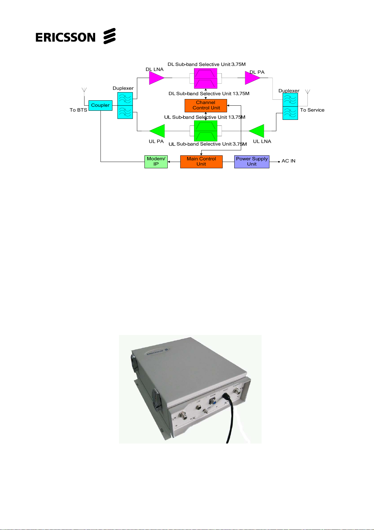
The repeater receives the downlink (DL) signal from BTS via the donor antenna, the
signal will be filtered by duplexer and amplified by low noise amplifier (LNA), and
then DL band selective unit will select operation band, and finally it will be amplified
by DL power amplifier (PA) unit and filtered by duplexer, sent via the service
antenna to the coverage area. There is a dual SAW filter in the DL band selective
unit, and it makes the band selectivity of the repeater viable.
The service antenna receives the uplink (UL) signal from mobile terminal; the signal
will be filtered by duplexer, amplified by the UL low noise amplifier (LNA) and filtered
by the UL band selective unit, and then amplified by the UL PA unit and filtered by
UL duplexer, sent via the donor antenna to the BTS. Certainly there is a dual SAW
filter in the UL band selective unit.
The main control unit will control the modules. User can inquire and modify the
parameters by LOC (local) interface, and we also can do it in the NMS (Net
Management System) by ways of SMS or data fax.
The PS (Power Supply) unit supplies power to all the active units.
Please refer to the following fig 2-1
Rev PA1 2010-1-12
Public
© Ericsson AB 20089
2 (10)
CDMA1900 Dual Band Selective Repeater 0.5W
Fig. 2-1 Configuration of CDMA1900 Dual Band Selective Repeater.
2.4 Product Features
• Good performance & good technical parameters.
• Modular structure, high reliable and easy to upgrade and maintain.
• With spontaneous heat dissipation.
• Local and remote monitoring function which access to the NMS.
• With a perfect protection function.
• Dual band for work, Sub-band 3.75MHz&13.75MHz.
2.5 Case Variants
425mm*372mm*160mm
12Kg
Fig.2-2 Outlook of CDMA1900 Dual Band Selective Repeater
Rev PA1 2010-1-12
Public
© Ericsson AB 20089
3 (10)

CDMA1900 Dual Band Selective Repeater 0.5W
2.6 Interface
Fig. 2-3 Interface of CDMA1900 Dual Band Selective Repeater
z TO SERVICE: Port of service antenna, N/F.
z TO BTS: Port of donor antenna, N/F.
z LOC: Port of local monitoring, RS232, 3-core waterproof
socket PLT-163.
PIN1: RX; PIN2
:
TX; PIN3: GND.
z AC(DC): Port of AC or DC power supply.
z ALARM: External alarm, socket PLT-167
z GND: Grounding
Rev PA1 2010-1-12
Public
© Ericsson AB 20089
4 (10)

CDMA1900 Dual Band Selective Repeater 0.5W
3 System Structure
Abstract
This chapter introduces the interior structure of CDMA1900 Dual Band Selective
Repeater 0.5W, which can help us to know the whole repeater by the introduction of
modules.
3.1 System Constitution
CDMA1900 Dual Band Selective Repeater 0.5W is composed of DL/UL LNA, DL/UL
Band Selective unit, DL/UL PA, modem, coupler for the modem, main control unit,
PS module and duplexer, etc.
3.2 DL/UL LNA
LNA is behind the duplexer, as the first amplifier, LNA is required to have good
performance such as very low noise factor and matched resistance. At the mean
while, there is a digital attenuator in the LNA, so we can get a gain adjustment from
0-30dB.
3.3 DL/UL Band Selective Unit
Signal is filtered by a narrow band SAW filter in the Band Selective Unit, so we can
well deal with the disturbance.
3.4 DL/UL PA
PA unit can amplify the RF signal to a high power level to meet the requirement of
coverage.
3.5 Coupler for Modem
Coupler for the modem provides necessary RF signal to the modem.
3.6 Modem
Modem is the ideal tool by which we can query and control the repeater from the
NMS.
Rev PA1 2010-1-12
Public
© Ericsson AB 20089
5 (10)

CDMA1900 Dual Band Selective Repeater 0.5W
3.7 Control Unit
Control unit controls the whole operation and provides the various functions such as
the alarm detection, local control, remote control and etc.
3.8 Duplexer
Duplexer separates or combines the UL and DL RF signal.
3.9 Power Supply
According to the different requirements, power supply can support AC 90~270V
Rev PA1 2010-1-12
Public
© Ericsson AB 20089
6 (10)

CDMA1900 Dual Band Selective Repeater 0.5W
4 Instruction for antenna selection
The equipment does meet the exemption requirements in respect of RF Exposure.
The following assessment is provided of compliance with the FCC limits for
maximum permissible exposure (MPE) to RF fields.
Based on the mathematical analyses described herein, the potential RF exposure
levels in all areas of possible interest should compliance with the applicable FCC
limit for controlled or occupational exposure. The proposed operation is therefore in
compliance with the FCC regulations and exposure limits.
The sections that follow provide the analysis and conclusions regarding compliance
Operational Data
Frequency Band: 1.9GHz
Antenna Dimension: < 0.5 meters height
Suggestion Antenna gain: 3~11dBi
Max Input power for antenna: 8~15dBm
Antenna Height AGL: 3 meters
Limits for Occupational/Controlled Exposure
Frequency
Range(MHz)
Power
Density(S)
(mW/sqcm)
Averaging Time
(minutes)
0.3-3.0 100 6
3.0-30 900/f*f 6
30-300 1 6
300-1500 f/300 6
1500-100000 5 6
Limits for General Population/Uncontrolled Exposure
Frequency
Range(MHz)
Power
Density(S)
(mW/sqcm)
Averaging Time
(minutes)
0.3-1.34 100 30
1.34-30 180/f*f 30
30-300 0.2 30
300-1500 f/1500 30
1500-100000 1 30
Rev PA1 2010-1-12
Public
© Ericsson AB 20089
7 (10)

CDMA1900 Dual Band Selective Repeater 0.5W
4.1 Applicable MPE Limits
The MPE limits are described in the FCC Rules and Regulations. For the frequency
range of interest here, the applicable limit for acceptable, continuous exposure of
the general population is 1.0 milliwatt per square centimeter (mW/ sq.cm), for
“controlled” occupational exposure, it is 5.0 mW/sq.cm.
4.2 FCC Formulas and Calculations
Base one the requirement of 47 CFR 2.1033, the device should operate and
installation support FCC RF exposure compliance.
FCC Bulletin OET 65 provides standardized formulas for calculating the power
density in both of the areas of interest here:
Equations for Predicting RF Fields Calculations can be made to predict RF field
strength and power density levels around typical RF sources. For example, in the
case of a single radiating antenna, a prediction for power density in the far-field of
the antenna can be made by use of the general Equations below. These equations
are generally accurate in the far-field of an antenna but will over-predict power
density in the near field, where they could be used for making a "worst case" or
conservative prediction.
S=
Where:
S = power density (in appropriate units, e.g. mW/sq.cm)
P = power input to the antenna (in appropriate units, e.g., mW)
G = power gain of the antenna in the direction of interest relative to an
isotropic radiator
R = distance to the center of radiation of the antenna (appropriate units,
e.g., cm)
Or
:
S=
Where:
EIRP = equivalent (or effective) is otropically radiated power
When
using these and other equations care must be taken to use the correct units for
all variables. For example, in the Equation, if power density in units of mW/sq.cm
is
desired then power should be expressed in milliwatts and distance in cm. Other units
may be used, but care must be taken to use correct conversion factors when
necessary.
Rev PA1 2010-1-12
Public
© Ericsson AB 20089
8 (10)

CDMA1900 Dual Band Selective Repeater 0.5W
Also, it is important to note that the power gain factor, G, in the Equation is normally
numeric gain. Therefore, when power gain is expressed in logarithmic terms, i.e., dB,
a conversion is required using the relation:
For example, a logarithmic power gain of 14 dB is equal to a numeric gain of 25.12.
For acceptable, continuous exposure of the general population is 1.0 mW/sq.cm
For “controlled” occupational exposure, it is 5.0 mW/sq.cm.
Express the equation in when we know P G and S
In this case:
P=500mW
G=14dBi
Then the general population safety distance to antenna should be:
D > 31.63cm
For “controlled” occupational exposure
D>14.14cm
Each area of interest should be addressed and consider the results of the
calculations.
4.3 Selection for Service Antennas
Panel Indoor Antenna 6/9/10dBi
If the equipment intended to deployed in the indoor use, the suggestion service
antenna can be select like this:
Frequency (MHz) 824-960 /1700-2200/2400-2500
Mechanical Specifications
Dimension (L x W x H) (mm) 210 x 180 x 44
Weight (kg) 0.9
Radiating element material copper & aluminum
Radome Material ABS
Operating Temperature (°) -30 - +60
Connector Type: N - F
Rev PA1 2010-1-12
Public
© Ericsson AB 20089
9 (10)

CDMA1900 Dual Band Selective Repeater 0.5W
Installation: wall mounting
Electrical Specifications 806 - 960 1700 - 2200 2400 - 2500
Polarization vertical vertical vertical
Gain (dBi) 6 9 10
Horizontal-3dB Beamwidth (°) 95 65 40
Vertical-3dB Beamwidth (°) 80 55 50
VSWR <1.4:1 <1.4:1 <1.4:1
Impedance (Ohms) 50 50 50
Max Input Protection (W) 50 50 50
Lightning Protection direct ground direct direct grounding
Logarithm Cycle Antenna 8dBi
Frequency (MHz) 824 - 960/1710 - 2500
Mechanical Specifications
Dimension L x W x H (mm) 280 x 220 x 60
Weight (kg) 2
Radiating element material copper & aluminum
Diameter Of Installation Pole (mm) φ40 - 70
Operating Temperature (°) -30 - +60
Max Wind Speed ( Km/h) 201
Connector Type: N - F
Installation: pole mounting
Electrical Specifications 824 - 960 1710 - 2500
Polarization vertical vertical
Gain (dBi) 8±1 8±1
Horizontal-3dB Beamwidth (°) 95 100
Vertical-3dB Beamwidth (°) 55 80
Front-to-Back Ratio (dB) ≥10 ≥10
VSWR <1.4:1 <1.4:1
Impedance (Ohms) 50 50
Max Input Protection (W) 50 50
Lightning Protection direct ground direct grounding
Rev PA1 2010-1-12
Public
© Ericsson AB 20089
10 (10)

CDMA1900 Dual Band Selective Repeater 0.5W
5 System Commissioning
This chapter describes the testing steps of fiber repeater system, the tools and
instruments needed for the repeater commissioning, as well as the general
commissioning test procedures.
5.1 Testing Tools and Instruments
Needed Instruments for the booster commissioning test are,
Spectrum Analyzer
Laptop
Test Mobile Phone
VSWR Tester
Multi-meter
Compass
Spanner
Local Control Serial Connection Cable (RS232)
5.2 VSWR Test of Antenna and Feeder System
To ensure the booster normal operation, we use VSWR tester to measure the
VSWR value of donor and service antenna. An engineering record is necessary.
The VSWR of the antenna and feeder system should be no higher than 1.5.
If not ok, check the connector again.
5.3 Voltage Test of Power Supply System
If with AC supply, there is an unstable voltage and a big fluctuation in the wide
countryside area, we should use the multi-meter to test AC voltage and make sure
the value range is from 85V to 132V with a good engineering record.
If with other power supply, we should testing the PS system value and have a good
engineering too.
5.4 Parameter Test
1 Connect the laptop with the repeater LOC interface via RS232, which is the local
control dedicated serial interface.
Rev PA1 2010-1-12
Public
© Ericsson AB 20089
11 (10)

CDMA1900 Dual Band Selective Repeater 0.5W
2 Ensure the donor antenna and the service antenna are not connected to the
repeater, switch on the repeater.
3 Run the local software on the laptop.
4 Confirm the DL PA and the UL PA is turnoff.
5 Calculate the DL gain as follows, and set it by local software.
According to the DL signal power Pin received by the donor antenna, the wanted
output power of the repeater Pout, calculate the DL gain, and set it by local software.
6 Connect the donor antenna and the service antenna to the repeater.
7 Switch on the DL PA by the local software, inquiry the DL output power. If the
output power is not less than the rating power, reduce the repeater gain until the
output power is 2dB smaller than the rating power, thus the repeater can work in
a good dynamic range.
8 According to the DL gain, estimate the UL gain and set it by the local software,
calculate the UL output noise level and slightly adjust the UL gain until the output
noise level meet the system requirement. Generally, UL gain is 3-10dB smaller
than DL gain.
9 Make calling test in the coverage area, make sure the calling quality and the
coverage range meet the requirement of the system.
10 If the wanted signal interrupts with the neighboring signal which is outside of the
wanted frequency range, we can filter it by setting a proper value to the UL or DL
frequency offset by the local software.
5.5 Remote Control Test
1 Shut down the PS of the repeater.
2 Place the SIM card to the socket on the Modem.
3 Turn on the repeater.
4 The power light on the Modem will light in 3 seconds. It shows the power supply
to the Modem is ok.
5 The communication light on the Modem will flash in 15 seconds and this may
last for 5 seconds. This shows that the Modem has registered successfully, or
you need to check the SIM card and the RF cable.
6 Set your telephone number to the WARN PHONE (phone number for alarm) by
the software.
7 Make an alarm, and check weather you will receive an alarm message. If you
receive, the Modem is ok.
Rev PA1 2010-1-12
Public
© Ericsson AB 20089
12 (10)

CDMA1900 Dual Band Selective Repeater 0.5W
8 Set the final phone numbers to the repeater, such as REP PHONE (repeater’s
phone number), WARN PHONE, CHECK PHONE1 (phone number for inquiry)
to CHECK PHONE5 of the OMC.
9 Set the REP ID (repeater’s ID) assigned from the OMC to the repeater.
10 Inform the OMC have a remote control test to the repeater
Note:
Any changes or modifications not expressly approved by the party responsible for
compliance could void the user’s authority to operate the equipment.
This device complies with Part 15 of the FCC Rules. Operation is subject to the
following two conditions:
(1) This device may not cause harmful interference,
(2) This device must accept any interference received, including interference that
may cause undesired operation.
Rev PA1 2010-1-12
Public
© Ericsson AB 20089
13 (10)

CDMA1900 Dual Band Selective Repeater 0.5W
Appendix A: OUTLET CONFIGURATION
1 Repeater(Remote Unit) 1
2 CD * 1
3 Swelled screw 4
Mark:CD includes the files:
1 User Manual;
2 O&M Manual;
3 Installation Direction Manual;
4 Specification;
5 Local Control Software.
Rev PA1 2010-1-12
Public
© Ericsson AB 20089
14 (10)
 Loading...