

Page 1
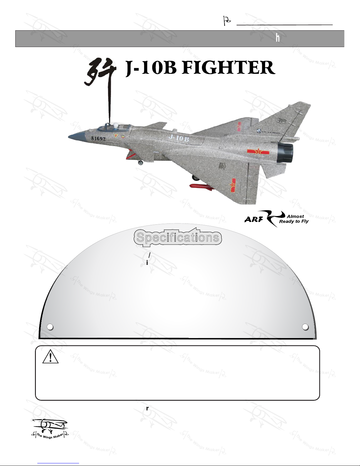
It is designed for maximum performance. Please seek advice if one is not familiar with this kind
of electric powered precision model. Operating this model without prior preparation may cause
injuries. Remember, safety is the most important thing. Always keep this instruction manual at
hand for quick reference.
Warning ! This model is not a toy.
THE WINGS MAKER
FACTORY PRE-FABRICATED
ALMOST-READY-TO-FLY (ARF) SERIES
MADE IN CHINA
* Specifications are subject to change without notice.*
www thewingsmaker com. .
SpecificationsSpecifications
Before commencing assembly please read these instructions thoroughly , .
INSTRUCTION MANUAL
Wing Span:28.7 in / 730 mm
Wing Area:310 sq in
/
20 sq dm
Flying Weight:28.5 oz
/
805 g
Fuselage Length:42.7 in
/
1085 mm
Requires: Outrunner Motor and Ducted Fan Propulsion
Unit (PL6800010), 4-channel “mixing radio” (elevator
and aileron) w/ 3 micro servos (SV2031), Brushless
ESC,
Li-Po battery and charger
3-cell power system recommendations: Outrunner Motor 28/31 (KM0283111), 30A (burst 35A) Brushless
ESC, 3 cells 11.1V 20C 2100mAh
Li-Po battery and charger
4-cell power system recommendations: Turbo Outrunner Motor For Ducted Fan (KM0283120), 40A
(burst 45A) Brushless ESC, 4 cells 14.8V 20C 2100mAh
Li-Po battery and charger
(
GM034XM
)
GM034XMPO29431311
Page 2
INDEX
BEFORE YOU BEGIN
BEFORE YOU BEGIN
PARTS LIST
ASSEMBLY
SAFETY PRECAUTIONS
P.1
P.2
P.3-P.10
P.10
Check all parts. If you find any defective or missing parts contact your local dealer. Please
DRY FIT and check for defects for all parts that will require CA or Epoxy for final assembly.
Any parts you find to be defective after the gluing process may be difficult to remove for
warranty replacement. The manufacturer will replace any defective parts, but will not extend
to the parts that are good before gluing to defective parts during assembly. Warranty will
not cover any parts modified by customer. For pre-assembled kits, please check proper
functions of all servos on the ground before flying. Servo gears could be damaged when
control surfaces are hit during transportation of models. The manufacturer will replace any
servos due to manufacturer`s defect, but will not cover plane crashes due to damaged
servos not detected before flying.
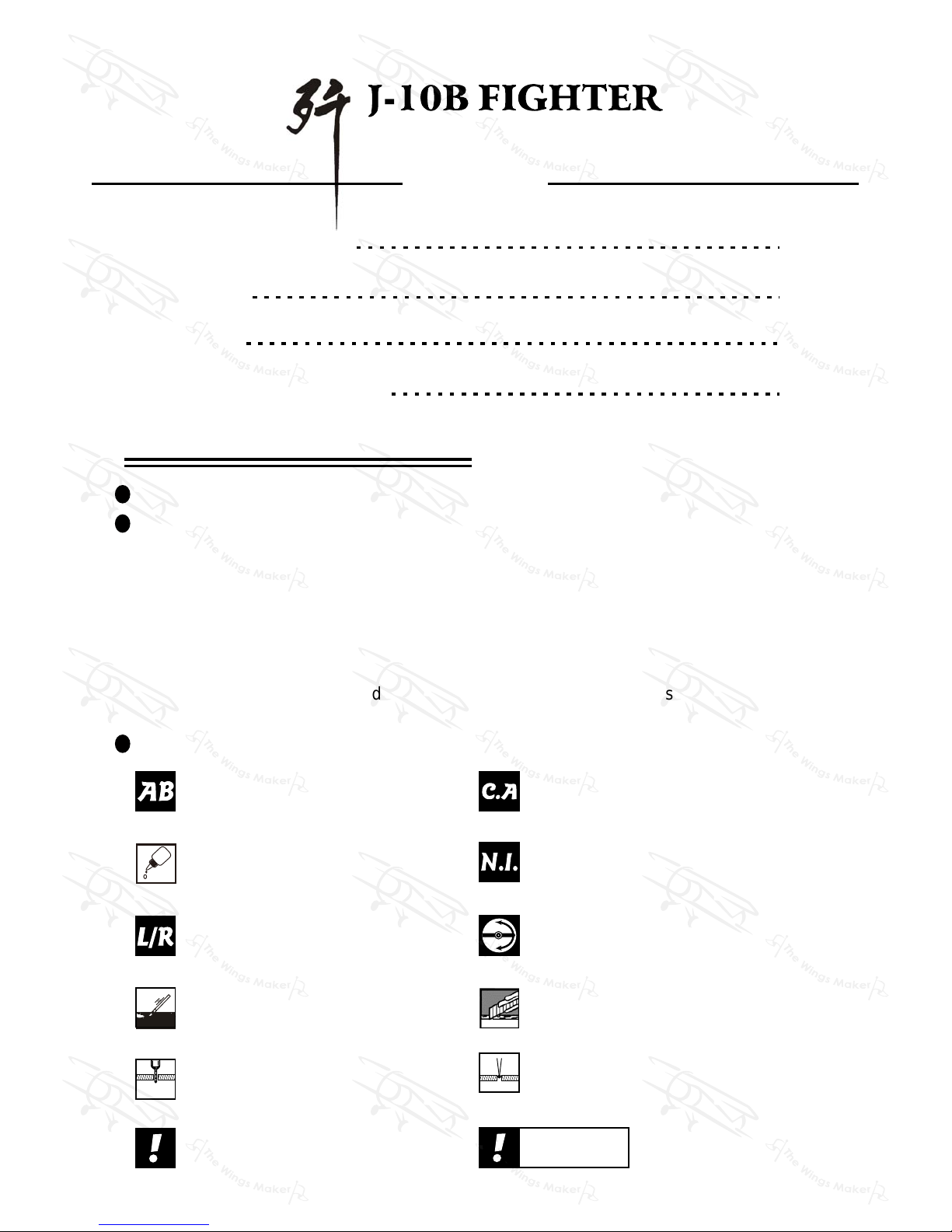
Symbols used throughout this instruction manual comprise of the following :-
Read through the manual before you begin, so you will have an overall idea of what to do.
1
2
3
P.1
Cut off shaded portion.
Ensure smooth non-binding
movement while assembling.
Apply instant glue
(C.A.glue, super glue.)
Assemble left and right
sides the same way.
Peel off shaded portion
covering film.
Pay close attention here!
Apply epoxy glue.
Must be purchased separately !
Drill holes with the specified
diameter (here: 3mm).
Pierce the shaded portion
covering film.
3mm
Do not overlook this symbol !
Warning!
Apply thread locker
GM034XMPO29431311
Page 3
Parts List
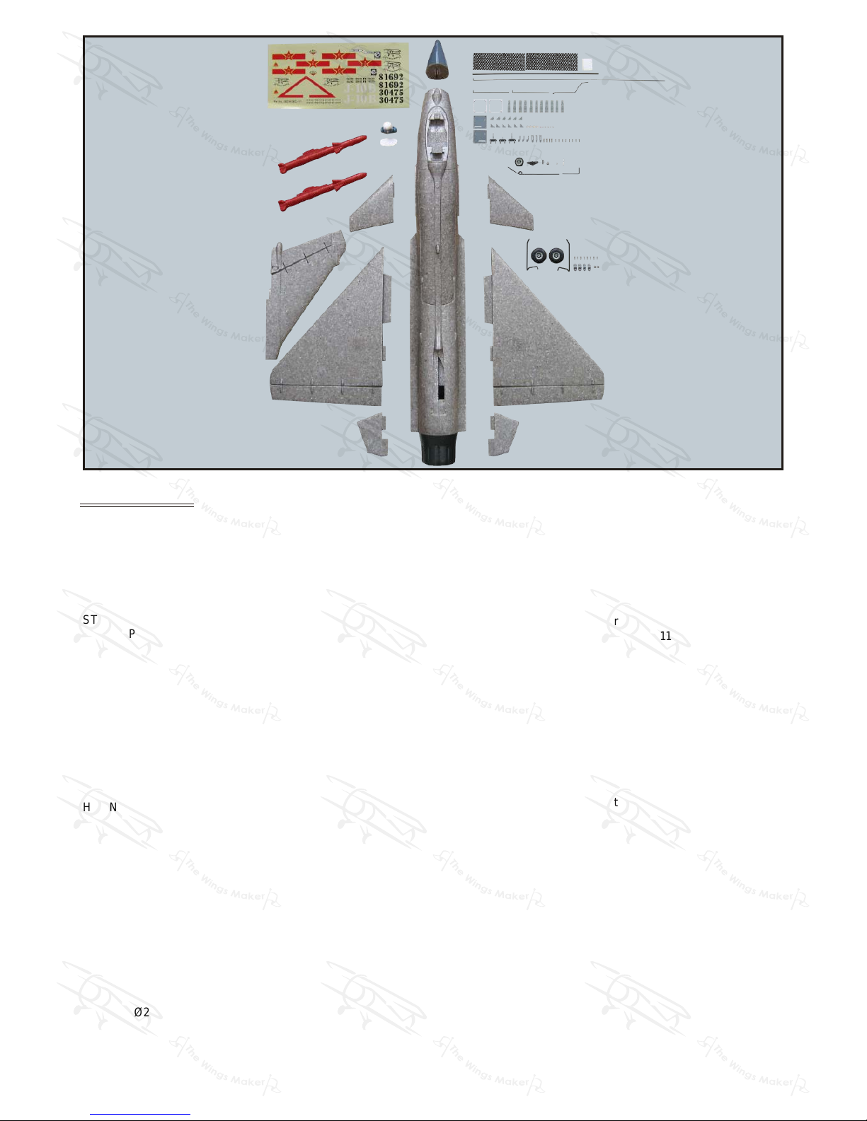
1.MAIN WING -- 1 pair
HINGES -- 8 pcs
PLASTIC BRACKET 36.5x36.5x2mm -- 2 pcs
2.SCREW PA1.7x8mm -- 8 pcs
SERVO MOUNTING PANEL PL5310020 -- 1 pair
STRAPER PL4112106 -- 2 pcs
CLEVIS PL4112105 -- 2 pcs
FUEL TUBE d2xD4x4mm -- 4 pcs
HORN PL4113103 -- 2 pcs
PUSHROD Ø1.4x102mm w/ Threads (For Aileron) -- 2 pcs
3.VERTICAL FIN & RUDDER -- 1 set
FUSELAGE -- 1 pc.
HINGES -- 3 pcs
4.PUSHROD Ø1.4x558mm w/Threads (For Rudder) -- 1 pc.
CLEVIS PL4112105 -- 1 pc.
FUEL TUBE d2xD4x4mm -- 1 pc.
HORN PL4113103 -- 1 pc.
5. SCREW PM2.5x8mm -- 4 pcs
WASHER d3xD7mm -- 4 pcs
DUCTED FAN COVER -- 1 pc.
6. NOSE PIECE -- 1 pc.
FRONT WING -- 1 pair
TAIL WING -- 1 pair
MISSILE -- 2 pcs
CARBON FIBER TUBE Ø4x360mm -- 1 pc.
MAIN LANDING GEAR Ø2.5x77mm -- 1 pair
LANDING WIRE STRAPS PL4114030 -- 4 pcs
MAIN WHEEL Ø40mm PL3117040 -- 2 pcs
COLLAR Ø2.6mm w/ Set Screw -- 2 sets
SCREW PA2.3x8mm -- 8 pcs
7. FUEL TUBE d2xD4x4mm -- 1 pc.
STRAPER PL4112106 -- 1 pc.
FRONT LANDING GEAR Ø1.8x137mm -- 1 set
FRONT WHEEL Ø23mm -- 1 pc.
COLLAR Ø2.1mm w/ Set Screw -- 2 sets
STEERING ARM PL4112215 -- 1 set
PUSHROD Ø1.2x106mm (For Front Wheel) -- 1 pc.
LINKAGE CONNECTOR 2.1mm HW7111050 -- 1 set
BATTERY TIE 160mm -- 1 pc.
ALLEN WRENCH HW134013S -- 1 pc.
8. BATTERY MAT 2x50x150mm -- 2 pcs
DOUBLE-SIDED TAPE 30x35mm -- 1 pc.
9. CANOPY -- 1 pc.
PILOT PC001042A -- 1 pc.
BATTERY COVER -- 1 pc.
10. DECALS: GM034DEC -- 1 set
P.2
GM034XMPO29431311
Page 4
Main Wing
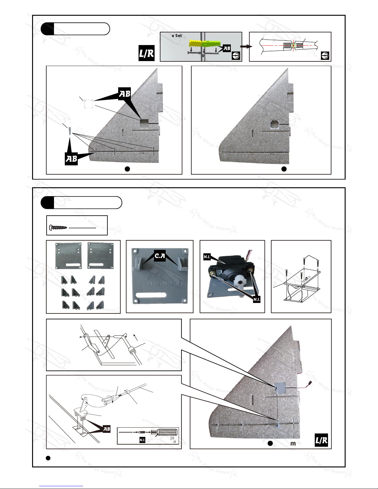
Aileron Servo
8
Bottom ViewBottom View
PA1.7x8mm Screw
Please choose either (02L & 02R) or (03L & 03R) or (04L & 04R) that suits your servo.
P A1.7x8mm
02L
03L
04L
02R
03R
04R
TWM PL8210010
CLEVIS WRENCH
Clevis
Pushrod
Ø1.4x102mm
Fuel Tube
d2xD4x4mm
Horn
Straper
Fuel Tube
d2xD4x4mm
Bottom View
P.3
1
2
Plastic Bracket
Hinge
2x36.5x36.5
Hinge Setting Hinge
GM034XMPO29431311
Page 5
Completed
Completed
A=A'
A
A'
TWM PL8210010
CLEVIS WRENCH
P.4
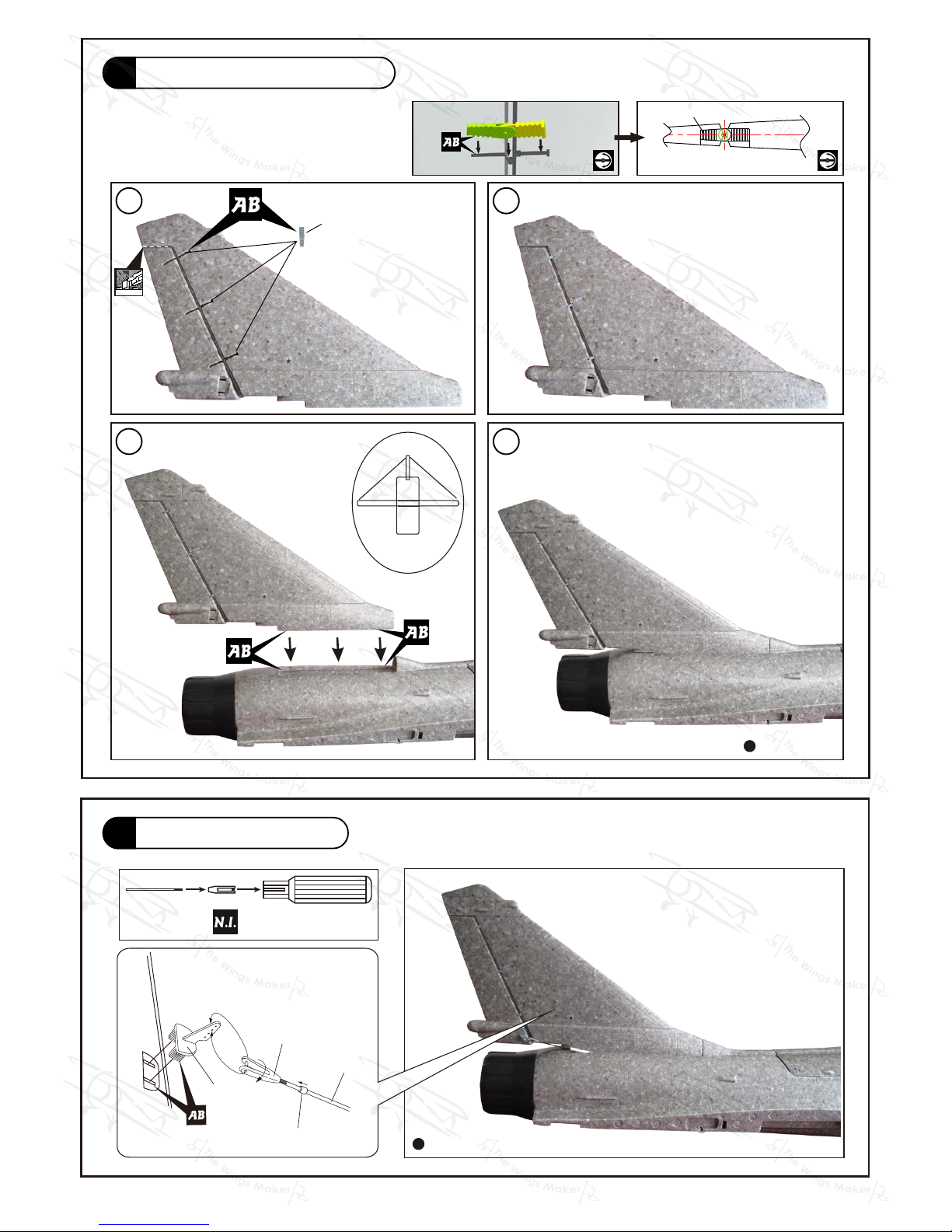
Vertical Fin / Rudder
3
Rudder Pushrod
4
Clevis
Pushrod
Ø1.4x558mm
Fuel Tube
d2xD4x4mm
Horn
Hinge
1
2
3 4
Hinge Setting Hinge
GM034XMPO29431311
Page 6
P.5
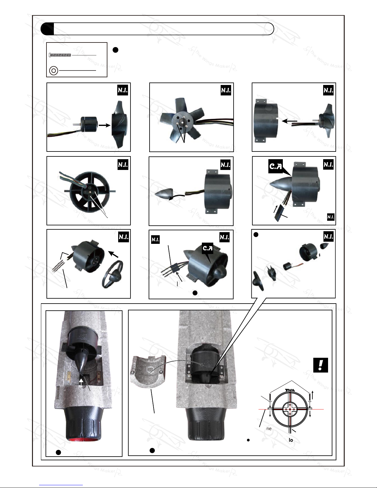
Make sure rotating motor casing is not in contact with
wirings or anything.
1
2
3
4
5
6
M3x6mm
PM2x4mm
7
Completed
d3xD7mm
Washer
PM2.5x8mm
4
4
Make sure TWM logo on ducted
fan stay on bottom of fusealge.
Center Line
Bottom
Optional Parts
Ducted Fan
Propulsion Unit PL6800010
& Outrunner 28 / 31 KM0283110
Solder
HEAT SHRINK TUBE
D5x30mm
HEAT SHRINK TUBE
Electric Wire
Electric Wire
Insulation
Motor wire lead
Ducted Fan Cover
Bottom View
Bottom View
PM2.5x8mm Screw
d3xD7mm Washer
Ducted Fan Propulsion Unit with 28/31 Motor
5
GM034XMPO29431311
Page 7
Completed
2
8
M3x3mm
Collar Ø2.6mm
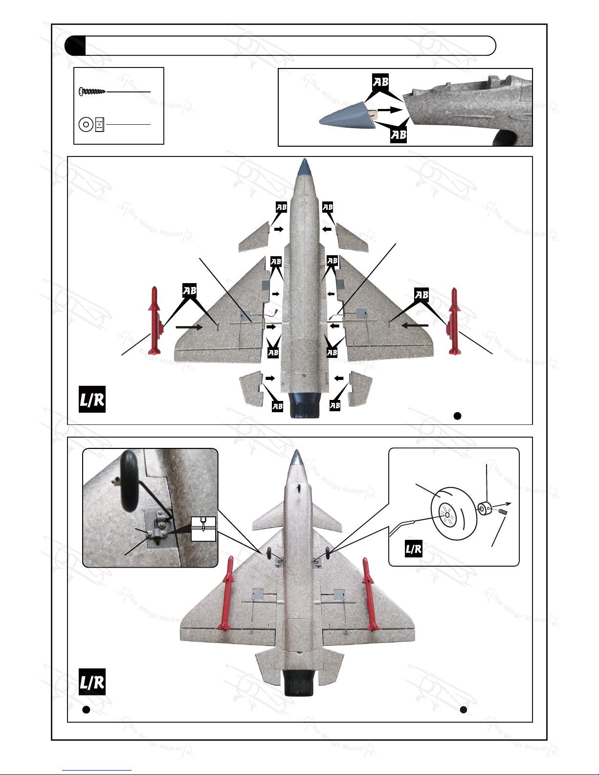
Missile
Main Wheel
Ø40mm
Bottom View
Bottom View
Missile
PA2.3x8mm
Landing Wire Straps
Main Landing Gear
1.5mm
P.6
Carbon Fiber Tube
Ø4x360mm
Aileron Servo Lead
PA2.3x8mm Screw
2.6mm Collar
Main Wing & Front Wing & Main Landing Gear & Missile
6
GM034XMPO29431311
Page 8
Top View
Bottom View
Completed
Front Landing Gear
Ø1.8x137mm
Collar Ø2.1mm
Steering Arm
PL4112215
Front Wheel
Ø23mm
Collar Ø2.1mm
M3x3mm
Set Screw
Collar Ø2.1mm
M25x3mm
Set Screw
.
Front
Battery Tie
M3x3mm
Set Screw
Steering Arm
PL4112215
Pushrod
Ø1.2x106mm
P.7
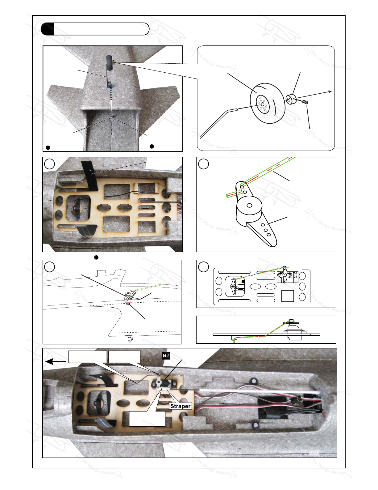
Front Landing Gear
7
Rudder Servo
1
2
3 4
Fuel Tube
d2xD4x4mm
Pushrod
Ø1.2x106mm
Linkage
Connector
GM034XMPO29431311
Page 9
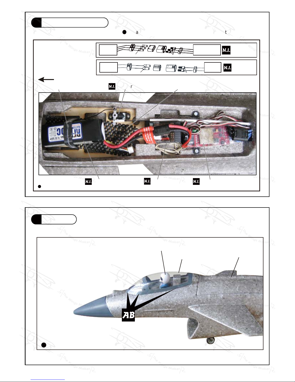
Front
Battery
Receiver
Battery Tie
Brushless ESC
Battery Mat 2x50x150mm
Install and arrange the equipment as shown in the picture.
Solder
Solder
TWM
KP0011310
ESC
Ducted Fan
Completed
Completed
Canopy
Pilot
Battery Cover
Rudder Servo
P.8
Radio Equipment
8
Canopy
9
Solder Solder
ESC
Battery
TWM
KP0011210
GM034XMPO29431311
Page 10
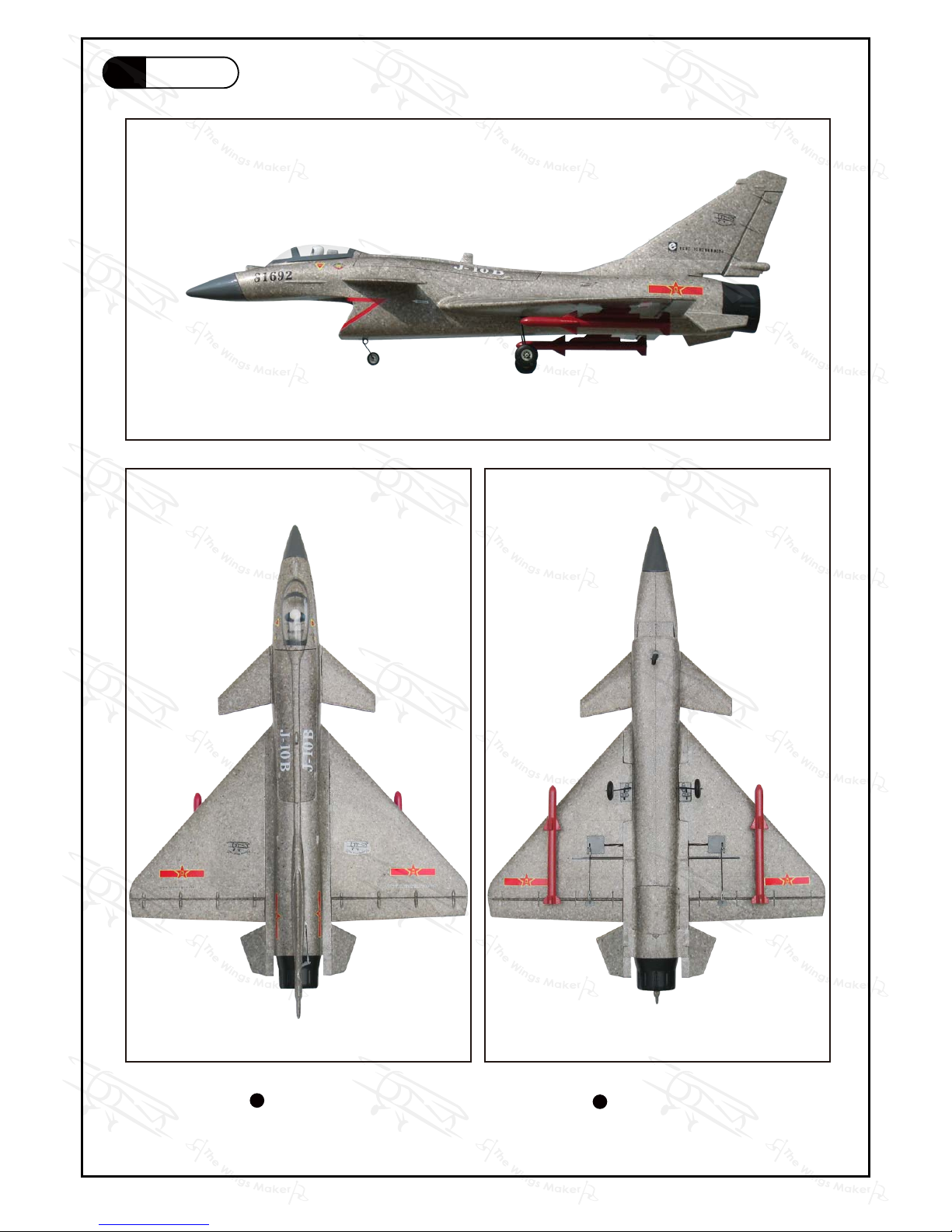
Bottom View
Top View
P.9
Decals
10
GM034XMPO29431311
Page 11
# is specially designed to be powered by KM0283110 / KM0283120
Outrunner Motor.
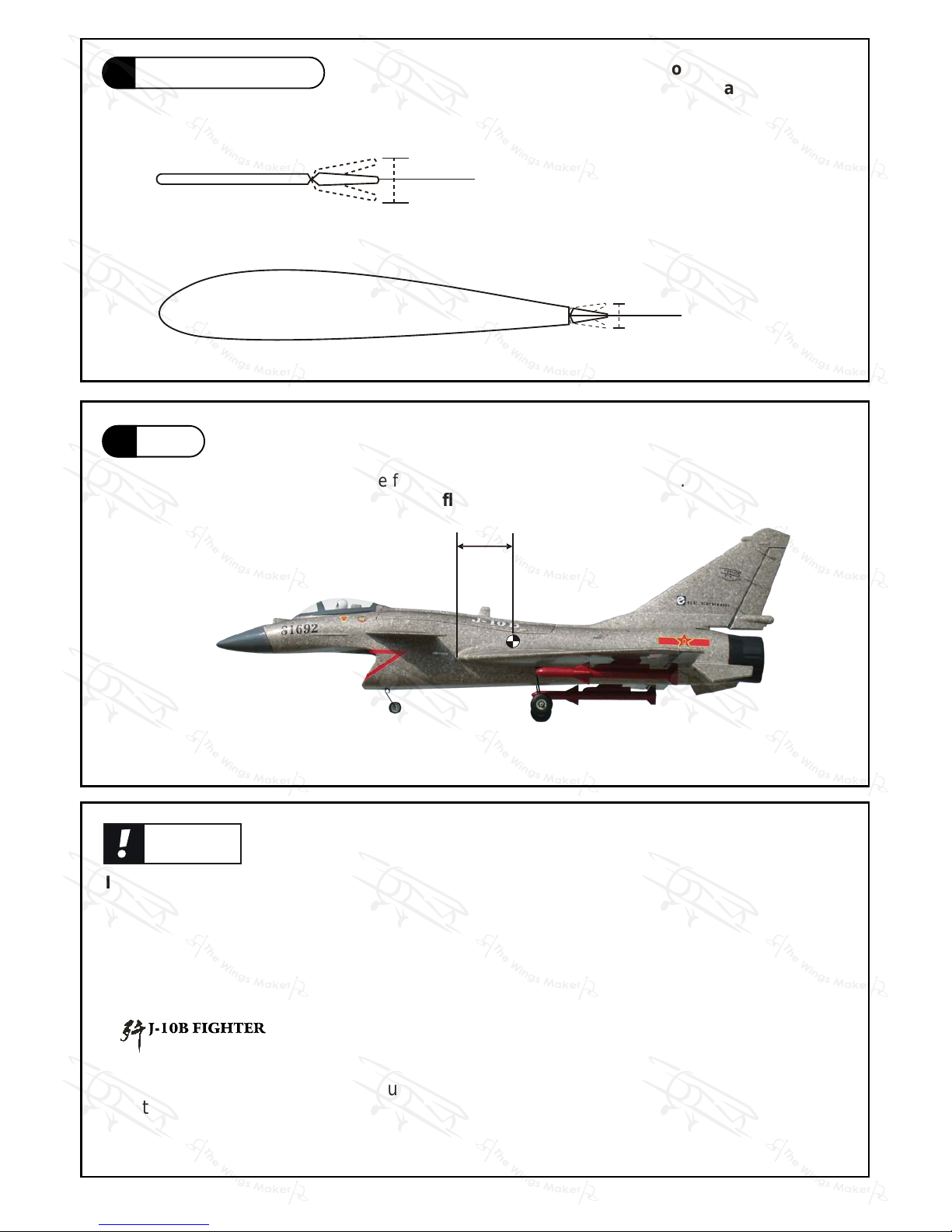
15 mm
15 mm
Ailerons/Elevator
18 mm
18 mm
Rudder
101.6mm
4 in
C.G.
Important Safety Precautions
Warning!
The ideal C.G. position is 101.6mm(4 in.)behind the leading edge measured
at where the wing meets the fuselage. In order to obtain the C.G. specified,
add weight to the fuselage or move the battery position.
Check the C.G. before flying.
Adjust the control throws as shown in
the diagram. These throws are good for
general flying. You can adjust according
to your personal preference.
# First time flyer should never fly by himself / herself. Assistance from experienced
flyer is absolutely necessary.
# Pre-flight adjustment must be done before flying, it is very dangerous to fly a badly
pre-adjusted aircraft.
# Make sure the air field is spacious, never fly the plane too close to people and never
get too close to a running propeller.
# Check and re-tighten up all factory assembled screws, use thread locker if necessary.
P.10
Control Throws
11
C.G.
12
http://www.thewingsmaker.com/instructionManuals.php
GM034XMPO29431311
Page 12
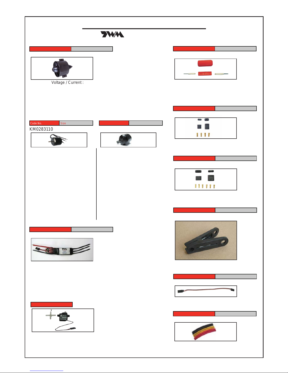
Optional Parts
40A Brushless ESC (2-4S)
Code No. Size Package
KC2040A02A 65 x 25 x12mm 1 pc
-Current : 40A continuous
-Burst current ( < 10 seconds) : 55A
-Weight : 43g (with wires)
-BEC output : Switch 5V / 3A
-Input :
Li - ion / Li - poly 2 - 4 cells;
Nimh / Nicd 5 - 12 cells
3 - Pin EZ Connector
Code No. Size Package
KP0011310 40A Max. Current 1 set
-ideal for electric models
-ideal for electric models
300mm Extension For Park Flyer
Code No. Size Package
KW0110300 300mm 1 set
Speed : 0.1 sec / 60° @4.8V
Torque : 16kg.cm / 22.2 oz - in @4.8V
Size : 22.4 x 11.4 x 20.0mm /
0.88x0.45 x 0.79in
Weight : 7.8 g / 0.28 oz
Code No SV2031
Micro Servo
Clevis Wrench
Code No. Size Package
PL8210010 1 set
Small Clevis
Large Clevis
( ACCESSORIES)
Ducted Fan Propulsion Unit without Motor
Code No. Size Package
PL6800010 1 set
-Operating Voltage / Current :
12V / 30A (35A Burst)
-Thrust : Approx. 560A
-Weight : 60g (without motor)
-Rotor diameter : 67 mm
-Outer casing diameter : 74 mm
-Color : Black
Outrunner for ducted fan
Code No. Size Package
KM0283110 1 pc
-Kv (rpm / V): 3600
-Operating Power: 375W
-Operating Voltage: 6 - 15V
-Operating Current: 30A
-Peak Current: 35A (max. 15 sec.)
-Internal Resistance: 25 m ohms
-Diameter: 28 mm
-Length: 31 mm
-Weight: 58g
-Shaft Diameter: 3 mm
-Shaft Length: 14.8 mm
-Mounting Screw:
M3 (Front) and M2 (Back)
-Distance of Mounting Holes:
16 mm and 19 mm (Front)
Turbo Outrunner for ducted fan
Size Package
KM0283120 1 pc
-Kv (rpm / V): 3030
-Operating Power: 660W
-Operating Voltage: 6 - 15V
-Operating Current: 45A
-Peak Current: 60A (max. 15 sec.)
-Internal Resistance: 28 m ohms
-Diameter: 28 mm
-Length: 31 mm
-Weight: 60g
-Shaft Diameter: 3 mm
-Shaft Length: 14.8 mm
-Mounting Screw:
M3 (Front) and M2 (Back)
-Distance of Mounting Holes:
16 mm and 19 mm (Front)
2 - Pin EZ Connector
Code No. Size Package
KP0011210 40A Max. Current 1 set
Heat Shrink Tube
Code No. Size Package
PT1115050 D5mm x 10cm 2 pcs x 3 colors
-Three colors (Black, Red, Yellow)
EZ Connector Puller
Code No. Size Package
PL8210030 1 set
Special tool for clevis installation.
Suitable for standard and small
(EP) clevis.
Page 13
THE WINGS MAKER
www.thewingsmaker.com
GM034XMPO29431311
 Loading...