

Wing Inflatables P4.7, P4.2, P5.8, P5.3 Operator's Manual

P-Series CRRCs
P4.2 / P4.7 / P5.3 / P5.8
OPERATOR MANUAL
Designed Smarter, Built Tougher.
Wing Inflatables, Inc.
1220 5th Street, Arcata, CA 95521
www.wing.com Phone (707) 826-2887

MISSION CAPABLE
(Come Hell or High Water)
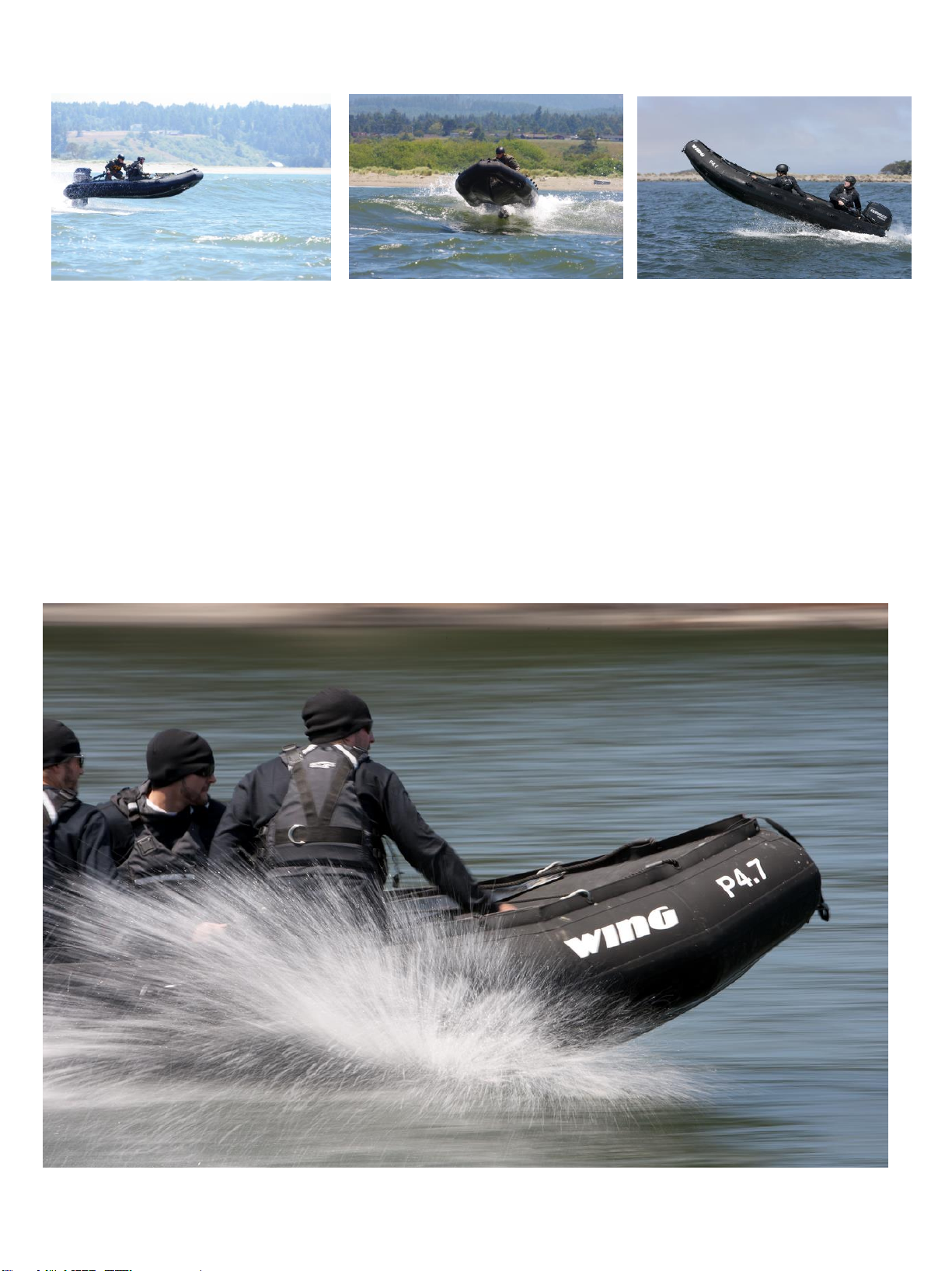
The Wing P4.2, P4.7, P5.3 and P5.8 CRRCs are the ideal inflatable boats for missions in which rapid deployment, high
performance, and reliability are key assets for success. Whether paddled for stealth or powered for speed, Wing’s
CRRCs are designed for a variety of military, law enforcement and scientific missions – from combat reconnaissance to
search and seizure; from boarding operations to search and rescue; from insertion and extraction of Special Forces teams
to maritime patrol, from oceanic atmospheric research to ecosystem protection . Whatever your need, we’ve got you
covered.
1| P a g e

Contents
IN THE BEST OF COMPANY ............................................................................................................................................................... 4
ABOUT WING INFLATABLES .............................................................................................................................................................. 5
Seven Key Reasons to Run One .................................................................................................................................................... 6
General Parts Diagram - All CRRCs ............................................................................................................................................... 8
Inflation Specifications ............................................................................................................................................................... 11
Assembly and Disassembly – Hard Deck .................................................................................................................................... 11
Floorboard and Thrustboard Installation ............................................................................................................................... 11
Inflating the Boat........................................................................................................................................................................ 13
Hard Deck Disassembly .............................................................................................................................................................. 14
Assembling the Roll-up Floor ..................................................................................................................................................... 14
Auto-Inflating the Boat .............................................................................................................................................................. 16
Prepare CRRC for Storage and Transport ................................................................................................................................... 17
Inflation Specifications ............................................................................................................................................................... 18
Pressure Relief Valves (PRVs) ..................................................................................................................................................... 18
Warm Weather Inflation Pressure ............................................................................................................................................. 19
Inflation Pressure Maintenance ................................................................................................................................................. 19
Outboard Engine Installation ..................................................................................................................................................... 20
Operational Tips on Boat Handling ............................................................................................................................................ 21
Wave & Wake Jumping .......................................................................................................................................................... 21
Impact with Hazards .............................................................................................................................................................. 22
Avoid Impact with Hazards .................................................................................................................................................... 22
Impact with Underwater Hazards .......................................................................................................................................... 22
Beaching the CRRC ................................................................................................................................................................. 23
Towing ........................................................................................................................................................................................ 23
Hoisting ...................................................................................................................................................................................... 24
Hoisting Sling .......................................................................................................................................................................... 24
Trailering .................................................................................................................................................................................... 25
Cleaning the Boat ....................................................................................................................................................................... 26
Storage ....................................................................................................................................................................................... 26
Valves ......................................................................................................................................................................................... 27
Fill Valves ................................................................................................................................................................................ 27
Flanges ................................................................................................................................................................................... 27
Pressure Relief Valves ............................................................................................................................................................ 27
Valve Cleaning ........................................................................................................................................................................ 27
2| P a g e

Valve Troubleshooting ........................................................................................................................................................... 28
Valve Removal ........................................................................................................................................................................ 29
Fabric Repair .............................................................................................................................................................................. 30
Liquids, Solvents, and Adhesive Agents use in Repair ........................................................................................................... 31
Recommended Adhesives Used In Polyurethane Repair ....................................................................................................... 31
“Flashing-Off” or “Drying to the Touch” ................................................................................................................................ 31
Damage Assessment .............................................................................................................................................................. 32
New Urethane Fabric Repair .................................................................................................................................................. 32
Using Goop or Adhesive ......................................................................................................................................................... 33
Repairs Using Tear Aid ........................................................................................................................................................... 34
Weathered or Coated Fabric .................................................................................................................................................. 35
Tears, Punctures & Large Repairs .......................................................................................................................................... 35
Bonding Patches to Urethane Fabric ..................................................................................................................................... 36
Large Tear: Inside/Outside Patch Repair................................................................................................................................ 37
Field Repair/Solvent Bonding Technique ............................................................................................................................... 40
Emergency Field Repair with Clamshell Plug ......................................................................................................................... 41
Inflation & Testing of a Repaired Tube .................................................................................................................................. 42
Repair Troubleshooting .............................................................................................................................................................. 42
General Boat Inspection ............................................................................................................................................................. 43
Boat Maintenance Do’s & Don’ts ............................................................................................................................................... 43
3| P a g e
IN THE BEST OF COMPANY
As an operator of the Wing P4.2, P4.7, P5.3 and P5.8 CRRCs you can be proud. You’re in the best of company, because
the craft beneath you is the finest of its kind. Wing CRRCs use the latest and best technologies available for manufacturing
rugged and durable inflatable boats. The boat(s) you’ve purchased were designed and built in the United States. Built by
highly dedicated professionals who care deeply about boating, about safety, and about the people who put their lives on
the line every day to serve their country. That’s why we set out to give you stronger, lighter, more maneuverable crafts –
crafts that will perform better and last longer than any other CRRCs in the market.
ATTENTION EXPERTS AND OLD HANDS
We know your ranks are filled with experts and seasoned
operators. They know how to drive a CRRC. They understand
what works and what doesn’t. They will quickly come to
appreciate the benefits of a Wing CRRC. Rather than getting the
“same old, same old,” your trained operators will be handed
something different: a CRRC that can handle any challenging
mission it’s asked to perform!
So how are the Wing CRRCs different? To start with, we use
better materials. Our heavyweight polyester fabric is coated with
Polyurethane. This means our boats are stronger and more
durable than other options out there. Repair and maintenance are
also easier and faster than models made from hypalon (CSM) or
other materials. Our floorboards and transoms are made from
high density, fiberglass-reinforced Polyurethane, with
fiberglass-reinforced plastic (FRP) layers on each side. This
means our transoms and floorboards are strong, flexible, and
impervious to rot or decay – lighter and stronger than either
wood or aluminum.
We’re also different because we have a unique design. Each Wing CRRC features a balance of design characteristics.
This design balance means the Wing CRRCs are versatile, allowing them to perform well in various sea conditions. They
feature comparatively high deadrise angles, for better performance and a more stable ride in rough, choppy seas. At the
same time, our main buoyancy tubes are designed for stability— forming downturned chines— to allow for a quick jump
onto plane and a smooth ride at lower speeds in calm water. Moreover, the square-bow design and broader beam translate
into more interior space – which means more room for gear and a more comfortable ride. Better performance and more
room – we think you’ll agree that these features will be tremendous assets to help you accomplish whatever mission
you’re assigned to perform!
Lastly, we’re different because Wing CRRCs are made right here in the USA. That’s right. American made. We’re
Berry Amendment compliant. That means all the fabric, rope, cords, and other components covered under the Berry
Amendment are of US origin. So we buy from suppliers who also make their products in the United States. Proudly
made in the USA by people who truly care!
Everything you need to know is right here in this manual. Assembly. Operation. Maintenance. Repair. Please read this
manual and then take your new Wing CRRC(s) out for a test drive. We’re confident you’ll see why we’re so proud of our
boats and how well they'll perform for you when you’re out there putting your life on the line in service to our country!
4| P a g e

“Run Hard, Run Fast—Save Some Lives. Kick Some Ass.”
— Bill Wing, Founder
ABOUT WING INFLATABLES
WHO WE ARE
Wing Inflatables is an all-US owned and operated company based in Northern California. We design and produce
inflatable products out of extremely durable, US made Polyurethane-coated nylon and polyester fabrics, using thermoand radio frequency welding techniques. We do this with assistance from proprietary CAD software written exclusively
for our fabric’s unique and superior characteristics.
Our product range includes inflatable boats, rafts, pontoons, fuel bladders, engine bags, foam collars, and air-holding
tubes for RIBS.
This line of inflatable products is managed by a cadre of dedicated engineers, designers, and craftsmen. We can build
to any specification while exceeding any expectation—for quality workmanship, product performance, and enthusiastic
customer support. This is our commitment and our guarantee.
WHAT WE ARE ABOUT
As the largest US owned and operated supplier of inflatable tubes, sponsons, and foam-filled collars for RIBs in service
with the United States military, we know what floats your boat. We’ve got your back. We build each tube and inflatable
boat with the same attributes found in our military, law enforcement and research professionals: strength, reliability,
durability, and unwavering commitment.
OUR MISSION
Our mission is to enable our nation’s military, law enforcement, first-responders and scientific researchers to perform
difficult and demanding operations with confidence and safety, by employing the finest inflatable boat in the world.
5| P a g e
WING CRRCS − TOP OF THEIR CLASS
Seven Key Reasons to Run One
#1 Polyurethane vs. hypalon. A polyester scrim coated with Polyurethane not only gives the Wing CRRC superior
tear, puncture, and abrasion resistance compared to hypalon (CSM) and PVC, the 1680 denier thread count adds
stiffness as well.
Consequently, an
inflated Wing is
more rigid yet
lighter than boats
made with lesser
materials. A
lighter, more rigid
boat is a faster,
more
maneuverable,
more efficient boat
to run.
#2 Thermowelded vs. glued
seams. Thermo-
welding bonds two
pieces of coated
fabric together as if
they were one.
Molecularly fused
using heat (not
adhesives as with
hypalon), welded
seams are far more
reliable than glued
seams. Expect a
greatly extended
service life and a
much longer shelf life for boats in long-term storage with welded seams over glued seams.
#3 FRP Composite transom and floorboards vs. plywood/ aluminum. FRP composite is nonabsorbent so it won’t
rot or decay. It is lighter than wood or aluminum and has a superior strength to weight ratio.
6| P a g e
#4 Tapered tube bow. Our tapered side tubes and squared-off bow creates 20% more usable hard-deck space in the
bow. On the outside, the squared-off bow directs air down into the V-hull assisting with lift and planing.
#5 Wing’s “V-Hull” design vs. lower buoyancy tubes (LBTs). With or without a load, the Wing CRRCs get up on a
plane fast—faster than the
LBT-equipped
competition. Eliminating
these unnecessary LBT’s
results in: less weight,
less draft, less drag, a
reduced wake profile, and
less stuff to go wrong.
The four-inch deadrise
from our main buoyancy
tubes (MBT) to the fabric
floor creates a tunnel
effect that assists in lift at
higher speeds.
#6 Dimensionally the
same as current inservice CRRC models.
For all the increased
performance, the Wing
CRRCs are identical bow
to stern, and port beam to
starboard, as the current
in-service CRRCs. Our
basic models weigh less
as well, so it will easily
match, fit, lift, install,
launch, trailer, or stow for
any mission, anywhere.
#7 Berry Amendment compliant. The Wing CRRCs are proudly made in the USA by skilled workers who care deeply
and passionately about the quality and performance of this unique craft as well as the special people who are called
upon to operate it during their missions.
7| P a g e
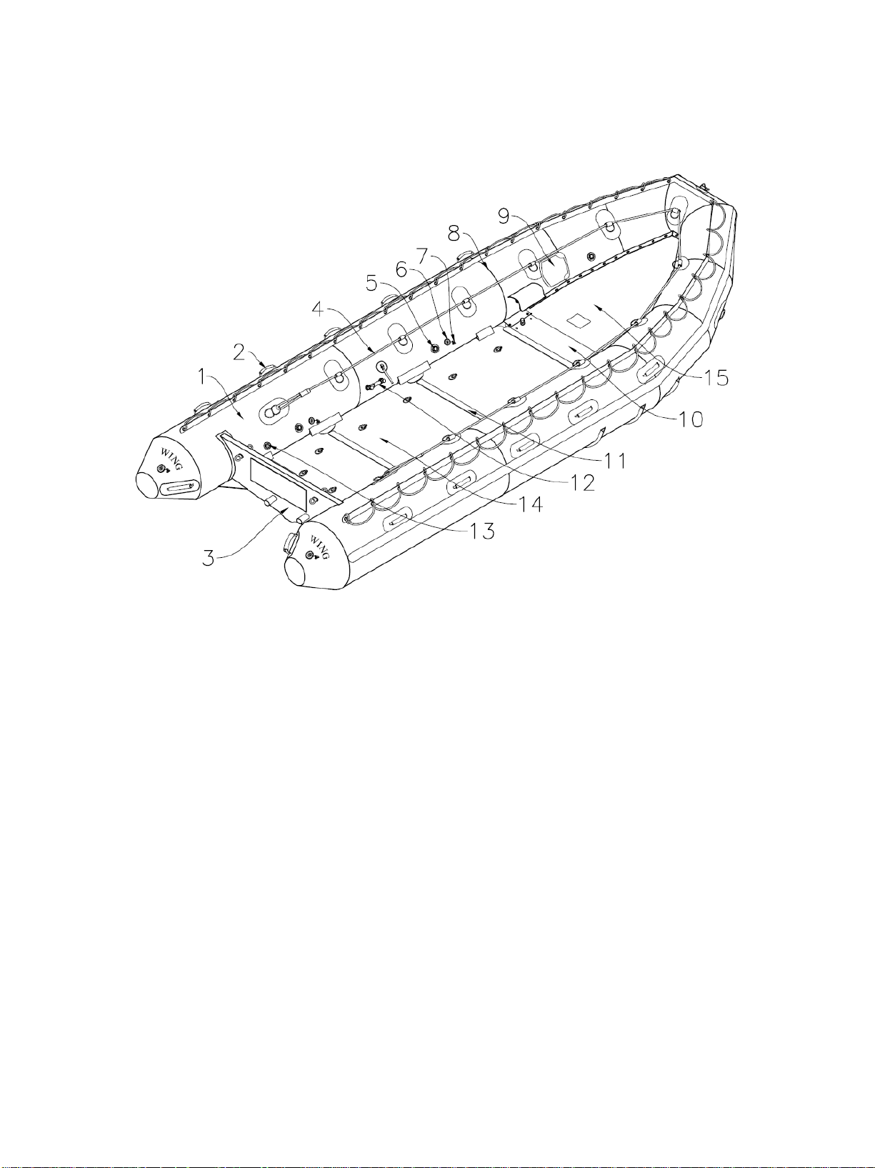
General CRRC Parts Diagram
1. Main Buoyancy Tube (MBT) – Primary inflatable structure of CRRC
2. Lifting Handle – Heavy duty handle placed on the outside of the MBT to enable the craft to be carried
3. Transom – Composite Structural beam at the stern on which an engine can be mounted
4. Inboard Lifeline – Line attached inboard on MBT
5. PRV – Pressure release valve
6. Fill Valve – Manual inflation valve
7. Fill Valve Cap – Protective cover for fill valve/redundant air seal
8. Seam Tape – 1” of Polyurethane material laid over welded seams
9. Paddle Holders – Secure paddles to MBT (certain models)
10. Main Thrust-board – FRP composite board near bow affords longitudinal support and provides attachment and
hoisting platform.
11. Floorboard Joiner – Aluminum extrusion mating two floorboards together
12. Air Chamber Crossover Valve For Single Point Inflation – Bypasses MBT baffle
13. Auto-Inflation Port – Valve where hose from inflation cylinder plugs into tube
14. Composite Hard Deck Floorboard – Creates hard deck surface (Number of floorboards depends on CRRC)
15. Bow Skirt – Protective laced in cover
8| P a g e

16. Cone – Stern end of MBT
17. Thermo Welded Seam – Two pieces of fabric Polyurethane fabric permanently fused using heat or RF welding
18. Rope Ring/D-ring combo
19. Grommet Strip – Strip of grommets along top of MBT
20. Rubstrake/Marley – Reinforcement material in high-wear area along the MBT
21. Heavy duty D-rings – Attachment points for mooring or towing
22. Sheet Floor – Polyurethane coated polyester forming CRRC hull
23. Keel – Inflatable tube running fore and aft giving form to fabric hull
24. Bottom Chafe – Extra layer of Polyurethane material in high-wear areas
25. Outboard Lifeline – Line attached outboard on MBT
26. Rubstrake/Marley cone end – Reinforced Marley abrasion material in high-wear area
27. Oval Transom Chafe – Fabric reinforcement for strength and stress-mitigation
28. Forward Thrustboard – FRP composite board forward of Main thrustboard affording additional longitudinal
support
29. Transom Motor Mount Plate – Metal plate attached to transom
30. Keel Fill Valve – Manual inflation valve
9| P a g e
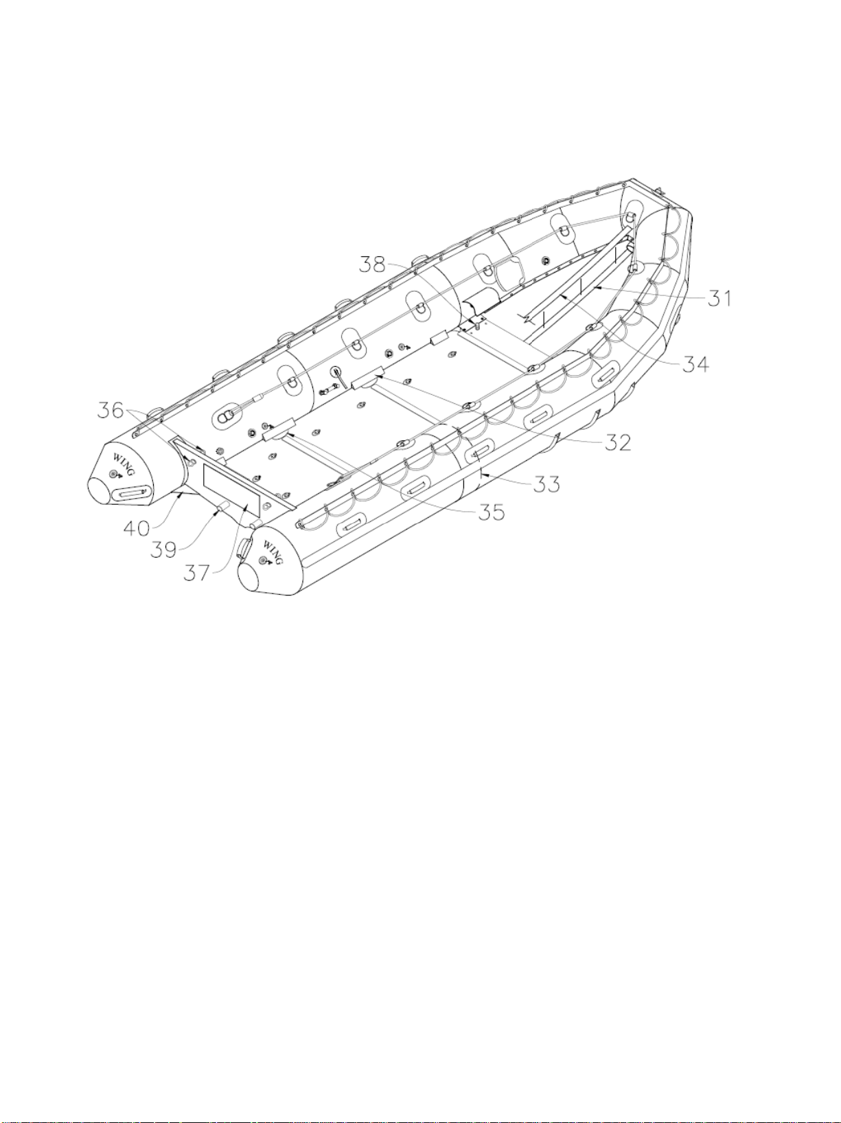
31. Floor Velcro strip – Attached to floor to mate with Keel Velcro strip
32. Floorboard Cleat – Retainer to prevent floorboard lift
33. Bulkhead/Baffle – Fabric wall creating separate chambers in MBT
34. Keel Velcro strip – Attached to keel for proper alignment of keel to floor
35. Gusset Joiner – Crescent shaped aluminum, mating two boards, along with main Joiner, for stiffening floorboard
assembly. Used for heavy load operations.
36. Towing/Lifting Eye – Dual-sided steel eye for towing and lifting
37. Sacrificial Plate – Attached to rear of transom
38. Bow Lifting Eye – Attached port and starboard side of main thrustboard
39. Scupper Drain – Allows water passage from inside to outside of CRRC
40. Transom Spray Deflector – Outboard of transom to minimize splash
10| P a g e
Inflation Specifications
Main Buoyancy Tubes
4.4 psi (303 mbar)
Keel
4.4 psi (303 mbar)
The Wing CRRC Main Buoyancy Tube is rated for normal operating pressure of 4.4 psi with ability to run up to 5.0 psi
with heavier loads. Each chamber is equipped with a Pressure Relief Valve (PRV) to ensure over-inflation does not
occur. However, over-inflation can occur if the PRV fails or is intentionally blocked. Use the supplied pressure gauge
to ensure each air chamber is properly inflated. Operating the boat below the designed working pressure of 4.4 psi or
above the PRV reseat pressure of 5.0 psi can cause performance issues and may damage the boat or pose a safety risk to
passengers. To avoid risk, always operate the boat with the MBT in the normal operating pressure range.
Minimum inflation pressure:
CAUTION: DO NOT UNDER-INFLATE!
Assembly and Disassembly – Hard Deck
Floorboard and Thrustboard Installation
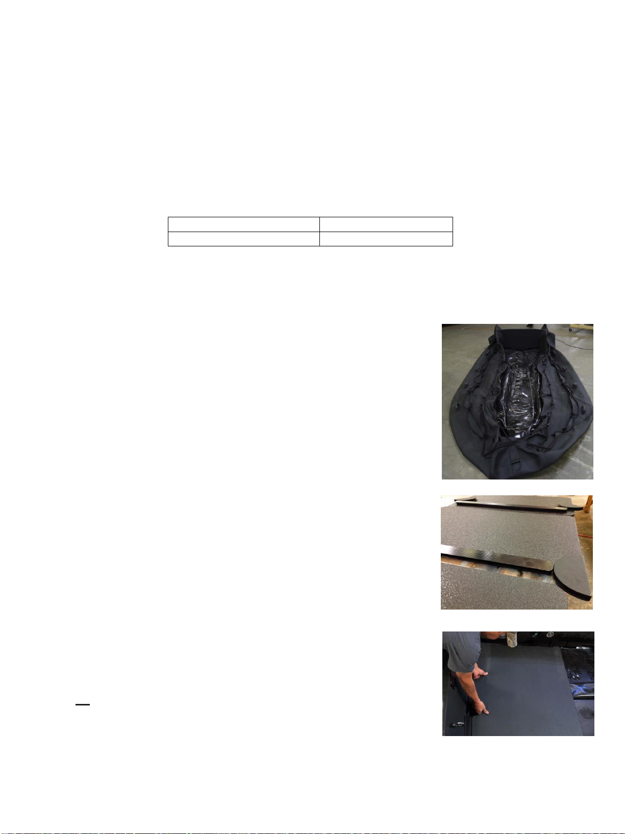
1. Unpack the boat.
Roll it out on a clean, flat surface.
2. Remove and inventory components.
A first “dry-run” assembly, with all parts in order, will quickly familiarize you with
your parts and greatly facilitate placing the items into your CRRC. Remove floorboards
(main floorboards; optional bow boards if ordered , step #11), thrustboard (s), joiners,
joiner gussets, and all hardware from the box. Lay out, alongside the boat, all
floorboards and assembly parts on a tarp or clean flat surface next to the boat, in the
proper order. Ref Drawings on page 8, 9, 10 &11.
3. Open cross-over valves and partially inflate the boat from the stern.
Partially inflate both sides of the boat, until the tube takes shape, but no more than
approximately 50%.
4. Ensure that the keel is properly positioned.
With the keel uninflated, center the keel Velcro with the floor Velcro, and that the keel
is fully inserted into the ends of the stern and bow keel pockets, and that the keel
retaining straps are loosely tightened around the keel. It’s important not to constrict the
keel with the lacing straps, once inflated. If in doubt, inflate the keel to verify position
and tightness of straps, then deflate the keel before the floorboard installation.
5. Insert aft floorboard section into transom batten.
Slide the aft floorboard (with cut outs placed facing transom) under the rear
floor cleats and into the floor battens on the transom. Press down on the floor
(either with your hands or by standing on the board) to ensure the floorboard
is underneath the floor retention cleats (Under the two aft 6” cleats and
11| P a g e
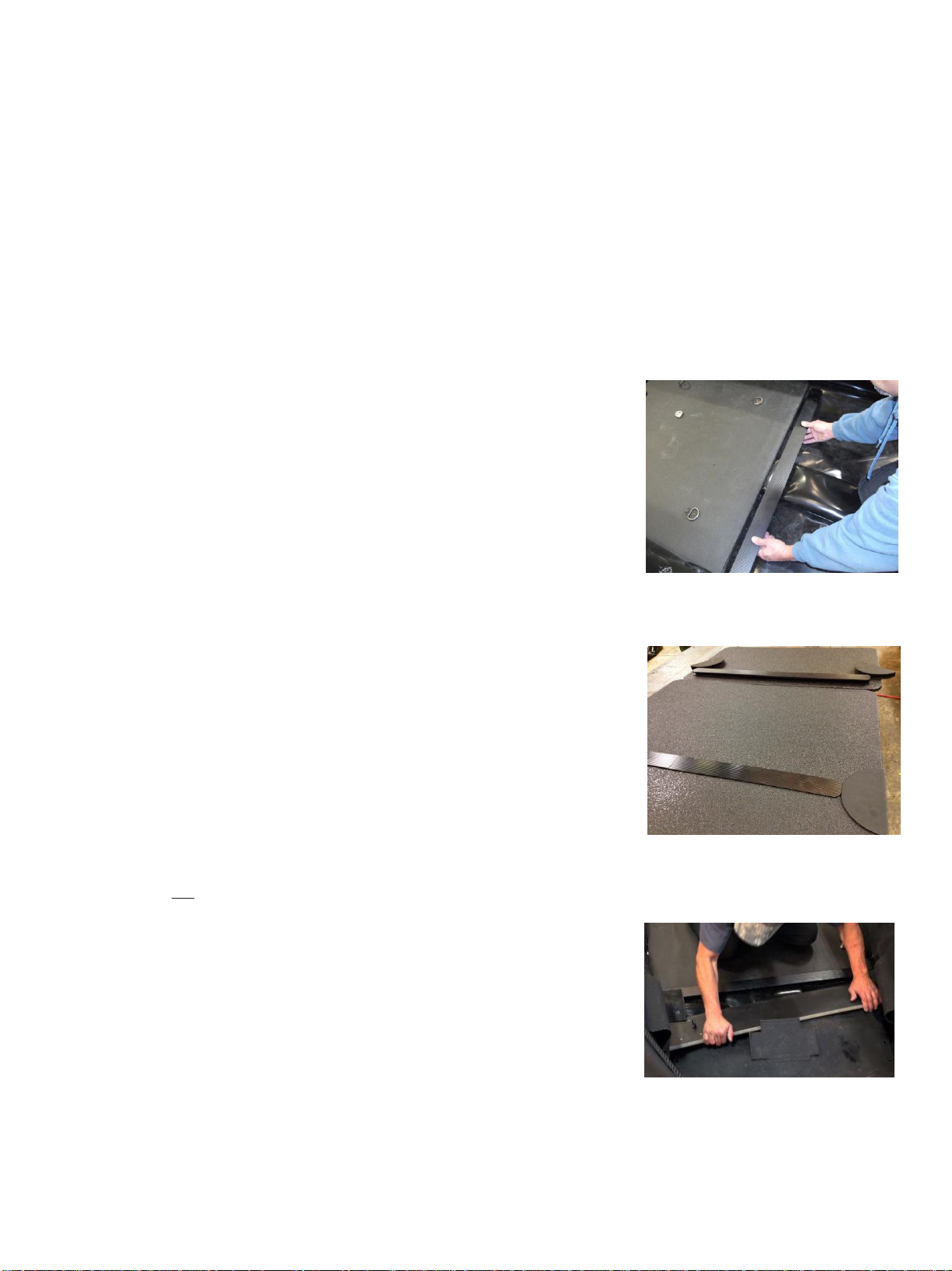
halfway under the two 18” cleats at the forward edge). Ensure that the
floorboard is pressed all the way to the transom and sits snuggly in the battens.
Wing Tip: Spraying the groove between MBT, cleats, boat bottom,
and along the surface of the keel, with soapy water (from a spray
bottle or damp rag not provided) reduces friction and allows for
easier installation of floorboards.
Wing Tip: Sit inside the boat and evenly press the board with your
feet towards the transom.
Wing Tip: Have a partner(s) help pull the partially inflated MBTs
slightly outward to help with floorboard install. If you are installing
the deck alone, pushing against the MBT on one side with your back
and the opposite side with your feet can also help.
6. Install aluminum gusset joiners.
Attach aluminum joiner gussets to both sides of floorboard, pressed tight against
each edge of the board, straight section outboard/curved inboard. Wing Tip: if the
fit is overly tight between the joiner gussets and the board, it can be easier to install
the gussets to the board prior to installing the board into the boat.
7. Install aluminum joiner.
Center and attach one long aluminum joiner (P5.3 & P5.8 have wider joiners) to
the leading edge of the aft floorboard.
8. Install 2nd floorboard.
Using a similar technique as in Step 5, slide the next floorboard section into
position, making sure it fits under the floor retention cleats, and is firmly seated in
the joiner. Wing Tip: ensure that each main board slides all the way to the rear,
and the gaps between boards-joiners-gussets are reduced as much as possible to
minimize “stacking” errors (i.e. cumulative gaps) in the final assembly. To aid with
this, webbing or cord can be used to pull the floorboard rearward, using the pad
eyes on the floorboards.
9. Repeat steps 5 through 7 for main floorboards 3 and 4 up to thrustboard.
Joiner gussets are not used between the fourth main floorboard and the thrustboard.
10. Slide the thrustboard into place.
Insert thrustboard (longest length aft) into the most forward main floorboard joiner
as shown, and pull rearwards into the joiner. Align the outboard attachment holes
in the thrustboard with holes in the fabric attachment flap. Do not yet install the
bolts through the thrustboard flaps. The thrustboard bolts will be attached later
(Step 15) after the entire floorboard system is installed and the MBT’s and keel are
inflated. For now, simply ensure that the holes for the hardware in the thrustboard
approximately line up with those in the thrustboard flap.
12| P a g e
 Loading...