

Winget PW170PH13/15, PW100PH10/11/12, PW140PH12, PW150PH8/11/12/14, Taskman PW170DY15 Operator's Handbook Manual
...
OPERATORS
HANDBOOK
TASKMAN
PRESSURE WASHERS
WINGET LIMITED
PLODDER LANE
BOLTON
GT MANCHESTER
U.K.
BL4 0LR
Tel: ++ 44 (0) 1204 854650
Fax: ++ 44 (0) 1204 854663
www.winget.co.uk
Issue 3 2010
EDGEFOLD INDUSTRIAL ESTATE
P.O. Box 41

CONTENTS
1 Introduction
2 Declaration of Conformity
4 Identification
5 Warranty Terms & Conditions
7 Safe Working
12 Operation
18 Maintenance and Service
22 Technical Information
25 Parts Listings

INTRODUCTION 1
The contents of this Handbook although correct at the time of
publication, may be subject to alteration by the manufacturers
without notice.
Winget Limited operate a policy of continuous product development.
Therefore, some illustrations or text within this publication may differ
from your machine.
WARNING: The operator must read both this handbook and the
Engine Operators Handbook and be familiar with all the controls
before attempting to operate this machine.
The contents of this handbook are designed as a guide to the
machines controls, operation, working capacities and maintenance. It
is not a training manual.
These are the original Instructions in the English Language
issued by Winget Limited & TASKMAN to comply with the requirements
of Directive 2006/42/EC
DECLARATION
OF
CONFORMITY
We: Winget Limited,
Of P.O. Box 41, Plodder Lane, Bolton, Lancs, England BL4 0LR declare that
the following TASKMAN Pressure Washers:Models:- PW100PH10/11/12, PW140PH12, PW150PH8/12/14, PW170PH15
PW170DY15, PW200PH13/15/21, PW200DY15, PW90PH12
Serial Numbers:- . 1000-99000 .
To which this declaration relates, with a maximum net installed power of
6.5Kw. Having been tested in accordance with the Conformity Assessment
Procedure detailed in Annexe V of Directive 2000/14/EC is in conformity with
the provisions of the “Noise Emission in the Environment by Equipment for
use Outdoors Directive 2000/14/EC”. Representative samples of this
equipment was tested and Sound Power Levels (Lwa) recorded of:-
PW100PH10 102db
PW100PH11 97db
PW100PH12 101db
PW140PH12 105db
PW150PH8 102db
PW150PH12 105db
PW150PH14 103db
PW170PH15 104db
PW170DY15 111db
PW200PH13 107db
PW200PH15 107db
PW200PH21 105db
PW200DY15 110db
PW9012 104db

We guarantee under the provisions of the above Directive (2000/14/EC) that
the Sound Power Levels for these equipment models will not exceed :-
PW100PH10 104db
PW100PH11 99db
PW100PH12 104db
PW140PH12 107db
PW150PH8 104db
PW150PH12 107db
PW150PH14 106db
PW170PH15 106db
PW170DY15 114db
PW200PH13 109db
PW200PH15 109db
PW200PH21 108db
PW200DY15 114db
PW9012 106db
We also declare that the above equipment is also in accordance with the
following EC Directives:-
2006/42/EC 2004/108/EC
Bolton 24.03.10 S. Hodge .
Place and date of issue Name and signature or equivalent
The above named person is also responsible for holding the Technical Documentation
applicable to the product to which this declaration relates and may be contacted at the
address which appears at the head of this declaration
Please take care of this document, as duplicate copies are not available.
This document is in accordance with EN45014:1989
marking of authorised person.
Joint Managing Director
Position
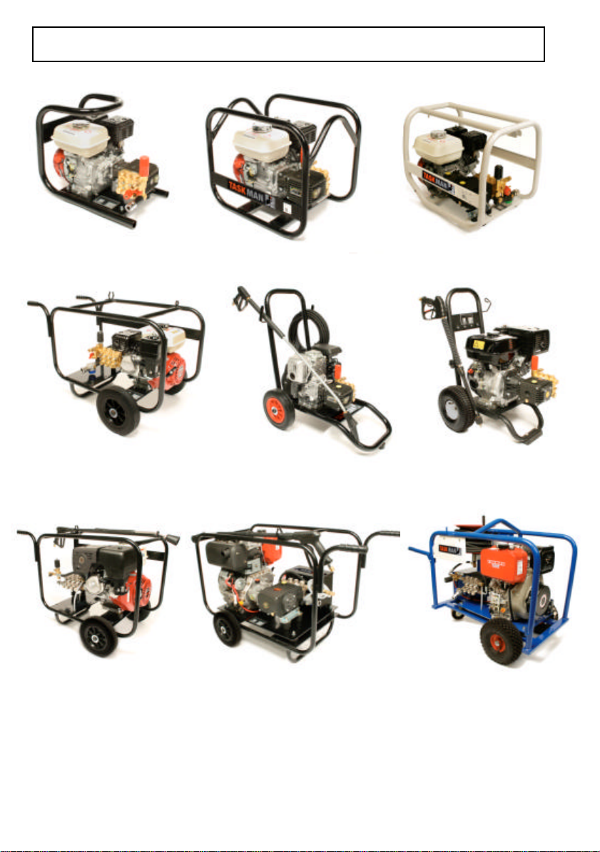
IDENTIFICATION 4
PW90PH12 PW100PH11 PW140PH12
PW100PH12
PW140PH12T PW100PH10GC PW170PH15
PW150PH12GC PW200PH13
PW150PH14
PW200PH15 PW200DY15E PW200DY15ES
PW200PH21

WARRANTY TERMS & CONDITIONS 5
Winget Limited assures you that if any of the parts identified within
the Parts section of this manual become defective due to faulty
manufacture or materials within 6 months from the date of purchase
when used commercially, or 12 months for domestic customers, the
part will be repaired or replaced under warranty free of charge by any
authorised Winget Limited Distributor.
Warranty repairs must be carried out by an authorised distributor,
unless prior agreement has been agreed in writing with the Warranty
Department at Winget Limited.
This warranty is given to the first owner and may be transferred to
subsequent owners for the balance of the Warranty period.
Winget Limited’s liability only extends to the costs of repair or
replacement of the faulty parts and necessary labour charges
involved in the repairs. The company accepts no liability for any
consequential loss, damage or injury, resulting directly or indirectly
from any defect in the goods.
Items not covered by Warranty and considered to be the customers
responsibility include normal maintenance services; replacement of
service items and consumables; replacement required due to abuse,
accident, misuse or improper operation; replacement of wearable
items e.g. hoses, lances, pins bushes etc.
All Warranty repairs on the petrol or diesel engine must be carried out
by the engine manufacturers authorised distributor.
The Warranty will not apply where the equipment is modified,
converted, or used for purposes other than those for which it was
designed, unless clearance for the modifications etc. have been
granted by Winget Limited in writing.
The Pre-delivery Inspection & Warranty Registration Document must
be completed correctly and returned to Winget Limited within 7 days
of the date of sale. Failure to do so could result in any subsequent
Warranty claim being rejected.
No claim will be considered if other than genuine Winget Limited
parts, which must be obtained via an authorised distributor,

WARRANTY TERMS & CONDITIONS 6
are used to effect a repair, or if lubricants other than those
recommended by Winget Limited and the engine manufacturers are
used.
The equipment must be serviced and maintained in accordance with
the service schedules laid down in this handbook. Evidence that
these have been complied with may be required before Warranty
claims are reimbursed.
Winget Limited have a policy of continuous product improvement
and reserve the right to change specifications without notice. No
responsibility will be accepted for discrepancies, which may occur
between the specification of machines and the descriptions
contained in publications.

SAFE WORKING 7
Safety is the responsibility of all persons working with and around
this machine. Think “SAFETY” at all times. Read and remember the
contents of this and the Engine Operators Handbook.
Any modifications to the machine will affect its working parameters
and reduce built in safety factors. Refer to Winget Limited before
fitting any non-standard equipment or parts. Winget Limited accept
no responsibility for any modifications made after the machine has
left the factory, unless previously agreed in writing. Winget Limited
will accept no liability for damage to property, persons or the
machine if failure is brought about due to such modifications, or
fitment of spurious parts.
This machine produces water at HIGH PRESSURE and as such is
potentially dangerous in operation. The high pressure water jet must
never be directed at any person, animal or at any electrical
equipment under any circumstances. If in doubt as to the suitability
of this machine for a particular task refer to Winget Limited.
Never commence work until the daily service checks have made
carried out.
Always report faults as soon as they are discovered.
Never fill fuel tanks whilst the engine is running.
Never leave the machine unattended with the engine running.
Never attempt to disconnect the high pressure hose from the
machine without first dumping any residual water pressure by first
pulling the trigger gun (Engine stopped)
Never use this equipment in areas of poor lighting.
Always wear eye and ear protection when using this machine.
Always keep the working area clear of people and animals
Always stay alert and watch what you are doing.

SAFE WORKING 8
Always be aware of the Lance Reaction Force when operating this
machine.
Always know how to stop the machine and bleed the water pressure
quickly.
Never over reach or stand on unstable supports, keep your footing
and balance at all times.
Never operate this machine from ladders or step ladders.
Never allow the machine to run dry of water or serious permanent
damage will be caused to the pump unit.
Never run the machine for more than 5 minutes with the trigger gun
in the closed position, this could result in a rapid rise in the water
temperature, which may damage the seals in the pump.
Never operate this machine under the influence of alcohol or drugs,
(many forms of medication can cause drowsiness) or when tired.
Never connect the machine to a hot water supply unless it is
specifically designed to handle hot water.
Always observe local Water Authority and Environment Agency
Bylaws when connecting this equipment to a mains water supply.
Always ensure the water supply is clean and free from contaminants.
Never allow contaminated water to enter drains, sewers or local
water courses.
Never allow unauthorised or untrained personnel to operate this
machine.
Never operate on any inclined or unstable surface.
Always drain the water from the hoses and pump on completion of
work, especially in cold weather, to prevent serious damage do not
allow the machine to freeze, protect from Frost.
Never use ether based cold start aids in aerosol cans to aid cold or
difficult starting.

SAFE WORKING 9
Never smoke whilst filling the fuel tank, mop up any fuel spills
immediately and in any event before running the engine and allow
time for any vapours from the spilled fuel to disperse before starting
the engine.
Never run the engine in an enclosed or confined area, exhaust fumes
in enclosed areas can kill.
Never stop diesel engines by means of the decompression lever,
serious damage can be caused to the cylinder head, piston and
valves.
Always avoid contact with the exhaust muffler, this can get very hot
when the engine is running and remains so for some time afterwards.
Always “dump” residual water pressure from the system before
leaving the machine. With the engine stopped pull the trigger until all
pressure is dissipated
Never leave the machine unattended with pressure in the water
system.
Always, where possible, work on or close to engines or machinery
when carrying out servicing or any maintenance, only when they are
stopped, if this is not practical, remember to keep tools, test
equipment and all parts of your person well away from moving parts.
Always wear correctly fitting clothing when carrying out servicing,
loose or baggy clothing can be extremely dangerous when working
on running engines or machinery.
Always “dump” pressure from the water system before carrying out
any kind of maintenance or adjustment.
Never allow unqualified personnel to attempt to repair, remove or
replace any part of the machine.
Always obtain advice before mixing oils; some are incompatible, if in
doubt completely drain, flush and refill.

SAFE WORKING 10
Many liquids used in this machine are harmful if taken internally or
splashed into the eyes. In the event of accidentally swallowing oils or
fuels, seek qualified medical assistance and advice.
Always dispose of waste oils and fuels into designated waste oil
storage tanks. If storage tanks are not available, consult your
distributor or local authority for the addresses of local designated
disposal points. Improperly discarded waste oils pose a threat to
wildlife. It is illegal to dispose of waste oil into drains, or water
courses or to bury it. The Environment Agency have the power to
impose heavy fines for breaches of the above advice.
Never allow oils and fuels to come into regular contact with skin.
This can lead to serious skin diseases, including, medical evidence
suggests, skin cancer. ALWAYS wear protective gloves when
handling oils and fuels whether topping up, draining or refilling.
Always wash your hands if oils or fuels come into contact with the
skin.
Always store fuels in small quantities in the correct specially
designed containers, which can be securely fastened. Store fuel in a
cool, well ventilated store away from sources of ignition.
Always top up the fuel tank at the end of a working day or shift to
prevent the formation of condensation on the inside of the fuel tank.
Always ensure that any Warning, Safety or Advisory Decals attached
to the machine are legible and clean, replace if damaged, defaced or
missing.
DIESEL POWERED UNITS ONLY
To avoid damage to the water pump and gearbox never allow the
engine to run on idle/tick over speed for prolonged periods of time.
ELECTRICAL STARTING SYSTEMS
Starting engines fitted flywheel charge windings with the battery
disconnected will cause irreparable damage unless the stator leads
to the rectifier/regulator have been removed.

SAFE WORKING 11
ELECTRICAL STARTING SYSTEMS (Continued)
Never remove any electrical cable while the battery is connected in
the circuit.
Only disconnect the battery with the engine stopped and all switches
in the off position
Always ensure that cables are fitted to their correct terminal, a short
circuit or reversal of polarity will ruin diodes and transistors.
Never connect a battery into the system without checking that the
voltage and polarity are correct.
Never flash any connection to check the current flow.
Never experiment with any adjustments or repairs to the system.
Always disconnect battery and charge windings before commencing
any electric welding when a pole strap/earth lead is connected
directly or indirectly to the engine.
Batteries contain sulphuric acid, which can cause severe burns, if
acid is splashed onto the ski, eyes or clothes flush with copious
amounts of fresh water and seek immediate medical aid.
WARNING & ADVISORY DECALS
The following warning and advisory decals are applied to the
machine
‘CE’ Decal Wear Eye Protection read operators manual

OPERATION 12
Never commence work until the daily service checks have been
carried out.
WATER SUPPLY CONNECTION
High speed pumps can be fed from mains water tap pressure
(POSITIVE PRESSURE) or draw from a tank or sump via suction
(NEGATIVE PRESSURE) however if used on suction (NEGATIVE
PRESSURE) for prolonged periods premature seal wear is likely to
result.
To run on either option please follow the instructions below :MAINS TAP PRESSURE (POSITIVE)
A clean water supply with a minimum of 15 Litres (3.3gallons) per
minute flow rate with a minimum pressure of 2 Bar (30psi) is
required. The inlet/supply hose should preferably have an internal
bore dimension of 19mm (3/4”) the minimum acceptable internal bore
dimension is 13mm (1/2”)
DRAWING FROM A TANK OR SUMP-SUCTION (NEGATIVE)
To use the machine to draw from a tank or sump the suction hose
assembly should be used. The suction hose has an internal bore
dimension of 19mm (3/4”) and should be as short as possible. The
“suction head “ should be kept to a minimum and in any event
should not exceed 610mm (2.0”) The water should be clean and the
tank/sump of sufficient capacity to prevent the pump running dry
whilst in use.

OPERATION 13
Never commence work until the daily service checks have been
carried out.
PRIMING THE WATER PUMP
Each time the machine is put into operation the water pump will
require priming before it will operate correctly. Priming the pump and
hoses removes any air which may be trapped in the system and
which may affect the correct operation of the pump and prevent the
full working pressure from being reached.
To prime the water pump follow the instructions below :-
Connect up the suction hose, if drawing from a tank keep the suction
hose as short as possible and never exceed 3 metres.
Start the engine and run up to 3/4 full speed
Hold the trigger gun open until a constant flow of water emerges, this
can take as long as 30 seconds, if after 30 seconds no water has
emerged stop the engine and investigate the cause.
Close trigger, increase the engine speed and use in normal manner.

OPERATION 14
Never commence work until the daily service checks have been
carried out.
LOW PRESSURE CHEMICAL APPLICATION
The Low Pressure Chemical Application facility is an optional extra
and may/may not be available on the machine.
Totally immerse the filter on the chemical suction hose in the
chemical solution container, connect the opposite end of the hose to
the chemical induction on the water pump.
The model PW9012 is provided with a metering control knob on the
front panel of the machine when the Low Pressure Chemical
Application facility is available. Turn the knob Anti-Clockwise to
increase the flow of chemical, turn Clockwise to reduce the flow.
Dependant on the type of Lance supplied follow the instructions
below induce the flow of chemical through the LANCE, Note chemical
will only be induced at low pressure.
One-Piece Lance assembly, turn the chemical applicator at the end of
the Lance anti-clockwise when viewed from the trigger gun. After a
short delay chemical will be automatically dispensed. To stop the
chemical application, turn the chemical applicator at the end of the
lance clockwise. After a short delay whilst the residue of chemical
works its way through the system the chemical flow will turn off
completely.
Two-Piece Lance, the end of the lance has a Multireg nozzle system,
this allows the angle of the spray to be adjusted by rotating the
nozzle and the pressure to be lowered by pushing the nozzle away
from the end of the lance. The amount of chemical flow induced is
regulated by the knob on the control panel. To stop the flow of
chemical, pull the nozzle assembly back towards the lance.
If chemicals have been used through the machine it is essential that
clean water is allowed to flush through the system until the chemical
residue completely disappears before the engine is stopped.
After the engine is stopped ensure all residual pressure in the
system is released by pulling the trigger gun.

OPERATION 15
Never commence work until the daily service checks have been
carried out.
STARTING THE ENGINE
Petrol Driven Units
Read the engine operators manual before attempting to start the
engine.
Connect the inlet/suction hose to a suitable tap or completely
immerse the inlet filter in the tank or sump. Turn on the tap
Ensure the lance is securely stowed
Turn on the fuel tap.
Close the choke lever, do not use the choke if the engine is warm or
the ambient air temperature is high.
Turn the engine on/off switch to “on”
Move the throttle lever slightly to increase the speed, do not fully
open the throttle at this stage.
Pull the starter grip lightly until resistance is felt, then pull briskly. Do
not wrap the starter cord around the hand, serious personal injury
could be sustained if the engine “kicks back” or backfires.
Open the choke as the engine warms up.
Prime the water pump as described above.
Open the throttle to the fully open position.
Do not allow the engine to run for more than 5 minutes with the
trigger gun closed, the water temperature will rapidly rise and will
cause damage to the water pump seals.
MODEL PW200 ONLY
As water enters the pump it will discharge through the EASYSTART
valve in the pump to atmosphere, this is correct. When the trigger

OPERATION 16
gun is operated the EASYSTART valve will close and the water will
stop discharging. Each time the trigger gun is closed water will
discharge through the EASYSTART valve again. This is a built in
safety feature of this unit to avoid overheating the pump and to ease
starting. The EASYSTART valve also releases any residual pressure
in the system automatically when the engine is stopped.
Never commence work until the daily service checks have been
carried out.
STARTING THE ENGINE
Diesel Driven Units
Read the engine operators manual before attempting to start the
engine.
Connect the inlet/suction hose to a suitable tap or completely
immerse the inlet filter in the tank or sump. Turn on the tap
Ensure the lance is securely stowed
Turn on the fuel tap, if fitted.
Move the governor lever/engine stop control to the start position.
Most small diesel engines are fitted with automatic decompression
levers, operate the lever as described in the engine operators
manual.
Grasp the starter grip and pull lightly until resistance is felt, then
return to the normal position. Still grasping the starter grip pull
briskly with a “jerking” motion. The engine should now start running
normally. If not, repeat the starting procedure. Do not wrap the
starter cord around the hand, serious personal injury could be
sustained if the engine “kicks back” or backfires.
Do not allow the engine to run for more than 5 minutes with the
trigger gun closed, the water temperature will rapidly rise and will
cause damage to the water pump seals.

OPERATION 17
To avoid damage to the water pump and gearbox (if fitted) never
allow the diesel engine to run on idle/tick over speed for prolonged
periods of time.
MODEL PW200 ONLY
As water enters the pump it will discharge through the EASYSTART
valve in the pump to atmosphere, this is correct. When the trigger
gun is operated the EASYSTART valve will close and the water will
stop discharging. Each time the trigger gun is closed water will
discharge through the EASYSTART valve again. This is a built in
safety feature of this unit to avoid overheating the pump and to ease
starting. The EASYSTART valve also releases any residual pressure
in the system automatically when the engine is stopped.
STOPPING THE ENGINE
Petrol Driven Units
If the machine has been used to apply chemical ensure it is
thoroughly flushed through with clean water before stopping the
engine.
Close the fuel tap and turn the engine switch to off, release any
residual pressure in the system by pulling the trigger gun.
In an EMERGENCY turn the engine switch to off.
STOPPING THE ENGINE
Diesel Driven Units
If the machine has been used to apply chemical ensure it is
thoroughly flushed through with clean water before stopping the
engine.
In an EMERGENCY move governor lever/engine stop control to the
stop position.
Never stop diesel engines by means of the decompression lever,
serious damage can be caused to the cylinder head, piston and
valves.

MAINTENANCE AND SERVICE 18
DAILY SERVICE CHECKS
Read the engine operators manual for items in addition to those
listed below.
Check condition of suction and pressure hose and lance.
Check suction filter, (if fitted)
Check the fuel level.
Check condition of air filter element, and clean replace as
necessary.
Check the oil levels in the engine, gearbox if fitted, and pump.
Refer to the engine operators handbook for advice on checking
engine oil level and for the correct grade of engine oil.
Pumps and gearboxes are fitted with either sight glasses or level
plugs/dipsticks.
In the case of sight glasses the oil level is correct when it is halfway
up the glass, some sight glasses are marked with a red dot to
indicate the correct level.
In the case of level plugs the oil level is correct when the oil is level
with the bottom of the threaded hole or if it just begins to trickle out
when the plug is removed.
In the case of dipsticks the correct level will be marked on the
dipstick.
Top up with the correct grade of oil, refer to the engine operators
handbook or the Technical Information section later in this
handbook.
If fitted, check tyre pressures.
Check the security of any covers or guards, do not use if any are
missing.
Check the security of engine/gearbox/water pump retaining nuts and
bolts.

MAINTENANCE AND SERVICE 19
Check all controls for correct operation.
Report any faults or missing equipment or damage immediately.
WEEKLY SERVICE CHECKS
Read the engine operators manual for items in addition to those
listed below.
All the daily service checks plus check condition of water filter and
clean as necessary, the water filter is normally located in the water
inlet port of the pressure relief valve, see page 20 to identify the type
of filter installed.
FIRST 20 HOURS
Change engine, pump and gearbox oils. Refer to the engine
operators manual for the correct grade of engine oil. Refer to the
Technical Information section later in this manual for the correct
grade of pump and gearbox oils.
EVERY 150 HOURS
Read the engine operators manual for items in addition to those
listed below.
Change pump and gearbox oils.
Refer to the Technical Information section later in this manual for
the correct grade of pump and gearbox oils.
Every 500 HOURS OR ANNUALLY
Read the engine operators manual for items in addition to those
listed below.
Change pump and gearbox oils.
Refer to the Technical Information section later in this manual for
the correct grade of pump and gearbox oils.

MAINTENANCE AND SERVICE 20
INLET FILTERS-IDENTIFICATION
CLEAN OR REPLACE INLET FILTERS FREQUENTLY
Filter Type A
Filter Type B

MAINTENANCE AND SERVICE 21
FAULT CAUSE REMEDY
Inlet Filter blocked or dirty
Pump running normally but
pressure low on installation
Pump running normally but
pressure low on installation
Fluctuating pressure
Pressure low after period of
normal use
Pump noisy
Presence of water in the oil
Water dripping from below
pump
Oil dripping Oil seal worn Check & replace if required.
Pump sucking air
Valves sticking
Unloader valve seat faulty
Inlet Filter blocked or dirty
Nozzle incorrectly sized
Worn piston packing
Inlet Filter blocked or dirty
Valves worn
Blockage in valve
Pump sucking air
Worn piston packing
Inlet Filter blocked or dirty
Nozzle worn
Suction or delivery valves
worn or blocked
Worn piston packing
Inlet Filter blocked or dirty
Air in suction lines
Broken or weak suction or
delivery valve springs
Foreign matter in the valves
Worn bearings
Excessive temperature of
water
Oil seals worn
High Humidity in the air
Piston packing worn
Piston packing worn
Plunger retainer O ring worn
Leaking connections
Check & Clean Inlet Filter
Check water supply &
possibility of air ingress.
Check & clean or replace.
Check & replace if required.
Check & Clean Inlet Filter
Check & replace if required
Check & replace if required
Check & Clean Inlet Filter
Check & replace if required.
Check & clean if required.
Check water supply & air
ingress at joints in suction
line.
Check & replace if required.
Check & Clean Inlet Filter
Check & replace if required.
Check & replace if required.
Check & replace if required.
Check & Clean Inlet Filter
Check water supply &
connections in suction line.
Check & replace if required.
Check & clean if required.
Check & replace if required.
Reduce below 75
centigrade.
Check & replace if required.
Check & reduce oil change
intervals.
Check & replace if required.
Check & replace if required.
Check & replace if required.
Check & tighten or reseal.
Excessive vibration in the
delivery line
Engine will not start
No water from nozzle
Inlet Filter blocked or dirty
Valves probably blocked
Switch in correct position
Fuel line is switched off.
Battery flat
Oil Alert activated (if fitted)
Inlet Filter blocked or dirty
Unloader in constant bypass
Blocked nozzle
Check & Clean Inlet Filter
Check & clean if necessary.
Check & correct.
Check fuel line & tank.
Check battery connections.
Check engine oil level.
Check & Clean Inlet Filter
Check & turn knob to
pressure.
Check & clean if necessary.

TECHNICAL INFORMATION 22
Model
PW90PH12
PW100PH11
PW100PH12
PH150PH8
PW140PH12
PW140PH12T
PW100PH10GCC
PW150PH12GC
PW150PH12GCC
PW150PH14
PW170PH15
PW200PH13
PW170DY15E
Pressure
Psi/Bar
1350/90
1500/100
1500/100
2250/150
2000/140
2000/140
1500/100
2250/150
2250/150
2250/150
2450/170
3000/200
2450/170
Engine
Honda
Petrol
GX120
Honda
Petrol
GX120
GX160
GX160
Honda
Petrol
GX160
Honda
Petrol
GX160
Honda
Petrol
GC135
GC190
GC190
Honda
Petrol
GX200
GX270
GX270
Yanmar
Diesel
L70
Flow
Ltr/min
12 N/A W1210 30 440x340x520
Gearbox
Type
11
N/A
12
8
12 YES W140 42 510x450x600
12 YES W140 48 640x600x1000
10
N/A
12
12
14
YES
15
N/A
13
N/A
15
N/A
Pump
Type
WW909
WW909
TT1508
AXD2520
TT512C
AXD3026
W154
WW961
UH2013
WW961
Weight
(Kg)
30
32
34
34
44
56
57
75
Dimensions
HxWxL(mm)
470x410x540
820x530x790
800x550x660
PW200PH15
PW200PH21
PW200DY15E
3000/200
3000/200
3000/200
Honda
Petrol
GX340
GX390
Yanmar
Diesel
L100
15
21
15
YES
YES
YES
WS201
WS202
WS201 128 780X660X1015
85
86
720x600x990

TECHNICAL INFORMATION 23
PW200DY15ES
3000/200
Yanmar
Diesel
L100
15 YES WS201 148 850x600x100

TECHNICAL INFORMATION 24
LUBRICANTS
Water Pumps
SAE20W/50 Engine oil
Gearbox
SAE90 Gear Oil
Engines
Yanmar L100 Diesel:- 10W30 or 20W40 API Classification CD
Honda Petrol Engines:- 10W30, 10W40, 15W40 API Classification
SF or SH

PARTS INFORMATION 25
TASKMAN WATER
PUMPS
PARTS SECTION
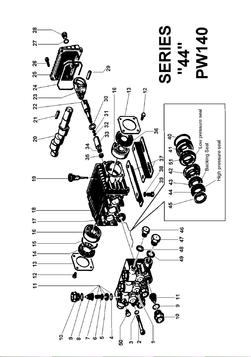
SERIES 44 PLUNGER PUMP FOR MODEL PW140
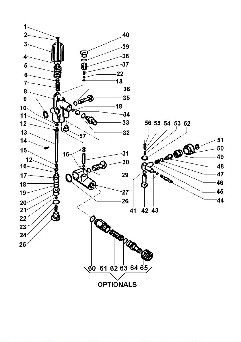
CONTROL SET W2-W2L FOR MODEL PW140

RS99 REDUCTION GEARBOX FOR MODEL PW140
VERSION V BUILT IN UNLOADER FOR PW140
Series 44

SERIES WS201 PLUNGER PUMP FOR PW200

RS151 REDUCTION GEARBOX FOR PW200

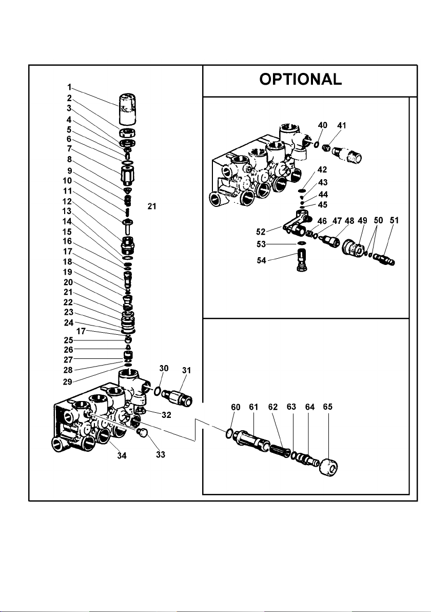
VRM UNLOADER VALVE ART612 FOR PW200

QUICK CONNECTION FOR PW200

SERIES W1507 PUMP FOR PW9012 (NPP12/9)

VERSION V UNLOADER VALVE FOR PW9012

SHAFTS & FLANGES VERSION A-B-C FOR PW9012

SERIES 1511 PLUNGER PUMP FOR PW100PH11

WW1511V UNLOADER VALVE FOR PW100PH11

CALIFORNIA
Proposition 65 Warning
Diesel engine exhaust and
some of its constituents are
known to the State of
California to cause cancer,
birth defects and other
reproductive harm
 Loading...