

Winget CUMFLOW RP150XD MK2 Parts & Operation Manual

CUMFLOW RP150XD MK2
ROTATING PAN MIXER
PARTS
&
OPERATION MANUAL
WINGET LIMITED
PO BOX 41
EDGEFOLD INDUSTRIAL ESTATE
PLODDER LANE
BOLTON
LANCS
BL4 OLS
Tel: ++ 44 (0) 1204 854650
Fax: ++ 44 (0) 1204 854663
crokersales@winget.co.uk
parts@winget.co.uk
service@winget.co.uk
www.winget.co.uk


INDEX
SECTION 1 GENERAL INFORMATION
1.1. Company Details
1.2. Important Notice
1.3. Mixer Operational and Safety Requirements
1.4 Installation Drawing
SECTION 2 INSTALLATION AND OPERATING INSTRUCTIONS
2.1. Pre Installation Notes
2.2. Installation Instructions
2.3. Operating Instructions
SECTION 3 TECHNICAL SPECIFICATION AND MAINTENANCE
3.1. Technical Specification
3.2. Shutdown Procedure and Maintenance
3.3. Lubrication
3.4. Gear Unit Maintenance
SECTION 4 MIXER SPARE PARTS
4.1. Mixing Pan & Drive
4.2. Mixing Star & Drive
4.3. Mixing Star Assembly
4.4. Mixing Star Lifting Arrangements
4.5. Layout of Guards
4.6. Micro Switch Cam & Proximity Switch
4.7. Electrical Switch Gear
4.8. Decals & Logos
SECTION 5 ANCILLIARY EQUIPMENT SPARE PARTS
5.1 Pan Trolley Four Wheels
5.2 MoD Additional Parts

SECTION 6 ELECTRICAL SYSTEM
6.1 Electrical Instructions
6.2 Wiring Diagrams
SECTION 7 MISCELLEANEOUS
7.1 Noise Details
The contents of this handbook although correct at the time of publication, may be subject to
alteration by the manufacturers without notice and Winget Limited can accept no responsibility for
any errors or omissions contained within the following pages. Nor can we accept any liability
whatsoever arising from the use of this manual howsoever caused.
Winget Limited operate a policy of continuous product development. Therefore, some illustrations
or text within this publication may differ from your machine
Winget Limited can accept no responsibility for incorrectly supplied parts unless the machine serial
number, part number and a full description of the items required is given when the order is placed.
NOTE
Imperial fixings (bolts, setscrews, nuts, washers etc) have been progressively changed to Metric. If
in doubt as to whether you have a Metric or Imperial fixing please order the metric items listed, i.e.
bolt or setscrew and associated or flat and spring washers to replace the existing items
NOTE
Electrical cables particularly those with copper conductors suffer from a condition known as
‘relaxation’ which may cause wiring to work loose over a period of time, it is recommended
that the tightness of wiring connections and terminals are checked following the first month
in service.

OPERATING
AND
MAINTENANCE MANUAL
SECTION 1
GENERAL INFORMATION
RP150XD MK2


COMPANY DETAILS AND GENERAL INFORMATION
For any spares or service work, please contact:-
Winget Limited
P.O. Box 41
Edgefold Industrial Estate
Plodder Lane
Bolton
Lancs
BL4 OLS
Telephone No: ++ 44 (0) 1204 854650
Facsimile No: ++ 44 (0) 1204 854663
‘E Mail’
crokersales@winget.co.uk
parts@winget.co.uk
service@winget.co.uk
ORDERING SPARES
To help us to complete your order promptly and correctly we need:-
• Machine type and serial number
• Description and quantity of parts required
• The full address to which the parts are to be sent
Winget Limited can accept no responsibility for incorrectly supplied parts unless the
machine serial number, part number and a full description of the items required is given
when the order is placed
.

IMPORTANT NOTICE
The CUMFLOW RP150XD MK2 (formerly the RP100HD) is a high performance mixer
The following precautions are necessary to obtain the best results and to avoid
damage to the MIXING STAR and PAN DRIVE
AGGREGATES
Strict control of graded aggregates must be maintained
Maximum size 19mm
Oversize lumps of aggregate or rogue materials must be prevented from
entering the Pan
MIXING STAR BLADES
They are to a special shape and material to prolong wear life. They should not
be modified in any way and only replaced with GENUINE ‘CROKER’ spares
obtained from WINGET LIMITED.
A daily check is advisable to ensure that the Blades/Wearing parts are secure
and undamaged.
MAXIMUM BATCH LOADS
UNDER NO CIRCUMSTANCES should the Maximum Batch Loads quoted
be exceeded nor should the mixer be stopped or re-started when there is a mix
in Pan
MIXING PAN
Ensure that the Mixing Pan is rotating concentrically and that the pan base is
Horizontal.
WARNING
THE MANUFACTURER ACCEPTS NO RESPOSIBILITY FOR ANY
DAMAGE OR FAILURE RESULTING FROM OPERATIONAL
MISUSE OR MALPRACTICE. ANY MODIFICATIONS TO THE
MACHINE WILL AFFECT ITS WORKING PARAMETERS AND

SAFETY FACTORS. REFER TO THE MANUFACTURERS BEFORE
FITTING ANY NON STANDARD EQUIPMENT OR PARTS.
THE MANUFACTURERS ACCEPT NO RESPONSIBILITY FOR ANY
MODIFICATIONS MADE AFTER THE MACHINE HAS LEFT THE
FACTORY, UNLESS PREVIOUSLY AGREED IN WRITING. THE
MANUFACTURERS WILL ACCEPT NO LIABILITY FOR DAMAGE
TO PROPERTY, PERSONNEL OR THE MACHINE IF FAILURE IS
BROUGHT ABOUT DUE TO SUCH MODIFICATIONS, OR THE
FITMENT OF SPURIOUS PARTS.

RP150XD MK2
OPERATIONAL AND SAFETY
REQUIREMENTS
PRE-DELIVERY
1.1 Drive coupling alignments, pan and star meshing of pan rack and drive gear.
1.2 Operating clearances star blade to pan. Fixed blade to pan wall.
1.3 Correct oil level in gearboxes. All grease points charged. Gear teeth greased.
1.4 No load test. Correct rotations.
PRE INSTALLATION
2.1 Check consignment.
2.2 Offload equipment using certified lifting gear of suitable capacity, by a competent
person (see separate chart for nett weight).
INSTALLATION
3.1 Refer to contract arrangement and site instructions.
3.2 Mixer to be mounted on supports of adequate strength and rigidity to prevent undue
vibration when mixing and securely bolted.
3.3 Mixer frame to be level on structure, add packers as required.
3.4 Check that pan is correctly seated and that pan rack and drive gear are in correct
mesh.
ELECTRICAL SERVICES
4.1 Refer to wiring diagram in Ops Manual. All wiring to be undertaken by competant
electrician, it is recommended that the mains electrical supply is provided via an earth
leakage circuit breaker. NOTE: electrical cables particularly those with copper
conductors suffer from a condition known as ‘relaxation’ which may cause wiring to
work loose over a period of time, it is recommended that the tightness of wiring
connections and terminals are checked following the first month in service.

OPERATION
5.1 Correct oil level in the gearboxes.
5.2 Check the Mixing pan clear of loose nuts and bolts to prevent damage to fingers and
blades.
5.3 Check correct rotation – mixing star – anti clockwise; mixing pan – anti clockwise.
All when viewed from the top.
5.4 Blade operating clearances adjust in line with maintenance instructions.
5.5 Never exceed manufacturer’s maximum capacity as detailed in specification.
SHUTDOWN
6.1 Prior to any work being carried out mixer to be isolated and physically locked off
6.2 Follow the procedures detailed in your companies Heath and Safety Policy at
all times.
6.3 Ensure all storage bins containing materials to be mixed are isolated.
MAINTENANCE
7.1 Ensure that all maintenance is carried out in accordance with the Parts and
Operating manuals and proprietary manufacturer’s specific instruction.
7.2 Isolate electrical and other services to the mixer as section 6 above.
7.3 Service at recommended intervals.
7.4 Use Croker manufactured replacement parts available from WINGET
LIMITED.
7.5 Ensure all safety guards and interlocks are reinstated prior to operating mixer.
GENERAL
8.1 Under on circumstances should the Maximum Batch Loads be exceeded by
either weight and volume as stated in Technical Specification.

8.2 Mixer star blades to be checked daily for damage.
8.3 Pan rim and base wearing plates must be replaced before excessive wear causes
distortion.
8.4 Ensure mixing pan is rotating concentrically and pan base is rotating in
horizontal plane.
8.5 Mixer must not be stopped and started when there is mix in the pan.
8.6 Refer to the Contract Drawing for scope of supply and the Site instruction notes
outlining weights etc.
8.7 Refer to Method Statement when installation and commissioning is
responsibility of Croker.
Nett Weights Max (kgs)
9.1 RP100XD 900 RP1250XD 4840
RP150XD 1100 RP1500XD 4980
RP200XD 1400 RP3000XD 7112
RP400XD 2000 FP1000 4040
RP550XD 2150 FP1500 4065
RP850XD 2600 FP2000 4100
9.2 Refer to technical specification for nett weights of ancillary equipment.
9.3 Refer to contract drawing for nett weights of ancillary equipment.
Miscellaneous
10.1 Noise. Measured in accordance with Article V of Directive 2000/14/EC
Noise Emission in the Environment by Equipment for Use Outdoors:- 105Lwa
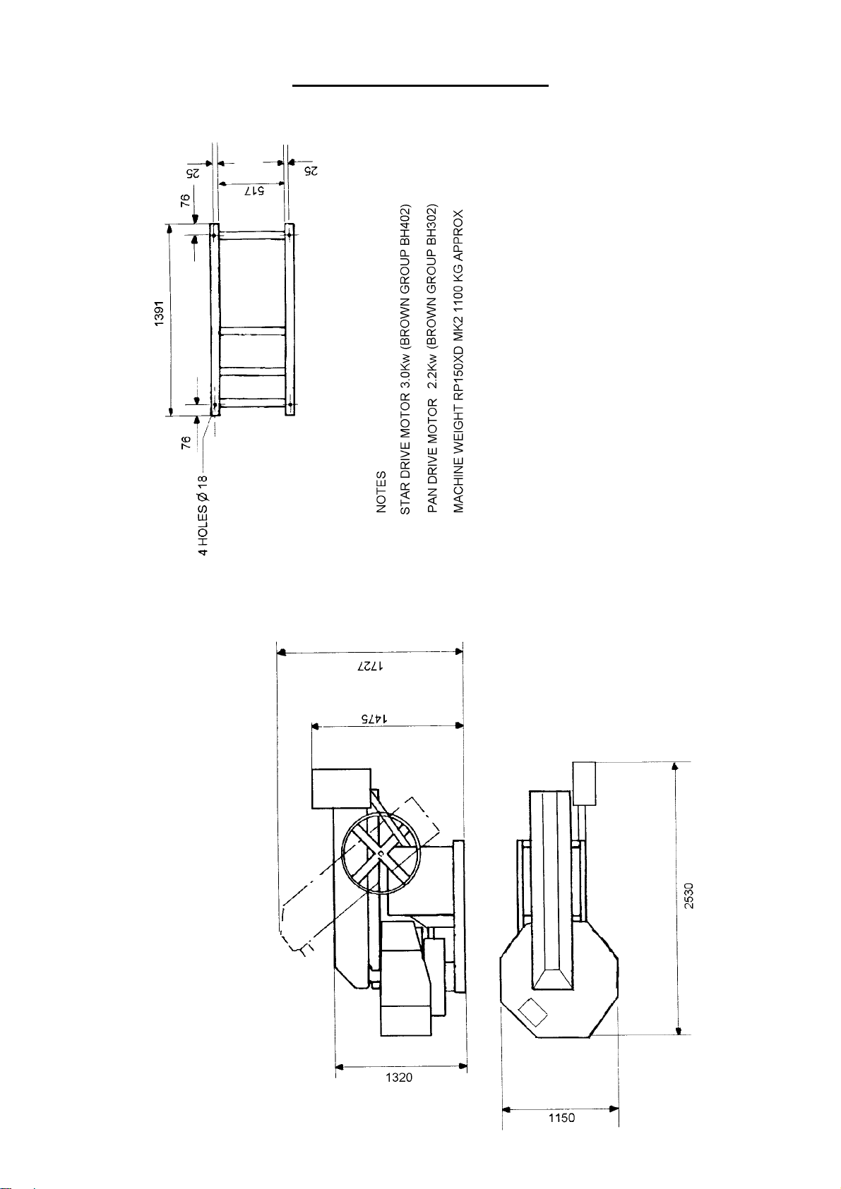
INSTALLATION DRAWING

OPERATING
AND
MAINTENANCE MANUAL
SECTION 2
INSTALLATION AND OPERATING
INSTRUCTIONS


PRE-INSTALLATION
On arrival of the equipment it is advisable to check that all packages listed on
the consignment note have been received.
The equipment must be offloaded using certified lifting gear of suitable
capacity, by a competent person.
An outline drawing and bolt hold plan is normally sent prior to the despatch of
the machine and will enable preparations to be made for the installation. With
the `picture` of what the machine will look like when it is assembled, the
ancillary equipment dismantled for transport can easily be identified.

INSTALLATION
Please refer to the contract arrangement and site instructions as applicable.
It is recommended that a concrete foundation (to take foundation bolts – not
supplied) should be provided for the machine to be mounted on
Before completing the installation, check that the main mixer frame is level
with a spirit level. Packings should be inserted as required under the main
frame. Check that the pan is seated and that the pan rack and drive gear are in
mesh.. Also check that all the blade clearances are in line with the maintenance
instructions.
On connecting to the power supply, the wiring diagram must be referred to.
Note:- it is recommended that the mains electrical supply is taken via an
earth leakage circuit breaker.
The wiring is correctly connected to the motors when the pan and star drive
rotate as follows:-
• The mixing pan and mixing star rotate anti-clockwise when looking from
the top.
NOTE:- the proximity sensors below the pan and star drive lifting
mechanism are fitted with small LED’s which light up when the sensors
are operating correctly.

OPERATING THE MIXER
Prior to start up, the following points should be checked:-
1) That there is oil in a) the pan drive gearbox
b) the star drive gearbox
2) The mixing pan should be clear of loose nuts, bolts, spanners, etc as
these will damage the fingers and blades.
3) Check that the blade clearances are correct and if necessary adjust, in line
with the maintenance instructions.
5) To raise the mixing star out of the mixing pan, turn the hand wheel in a
clockwise direction until the arm is at 45’
6) To lower, turn the hand wheel anti-clockwise and lower gently. The
mixer will automatically start if the mixing pan is in position. When the
mixing pan is removed the mixer cannot be operated as the proximity
switches need to sense the pan in position to complete the electrical
circuit
7) On completion of the mixing cycle the raising of the mixing star operates
a limit switch which automatically stops all moving parts
8) The pan can then be removed by hand or with the special lifting trolley
available as an option
IMPORTANT:
After each mix the contents of the pan must be completely discharged.
At the end of each period of operation the mixing pan, mixing blades, and
fingers, must be washed down to prevent product setting on them and so
impairing the efficiency of the machine. NOTE:- isolate the electrical supply
before washing down the mixer and do not aim the water jet directly at the
electrical control panel or related switch gear or sensors

OPERATING THE MIXER
SAFETY NOTES
Never operate the mixer unless you have read and fully understand the contents
of the Operators Manual
Never operate the mixer whilst wearing loose fitting clothing
Never reach inside the Pan whilst it is rotating
Never operate any equipment unless you have received adequate training
Cement, certain other minerals and organic compounds can cause skin irritation
leading to Dermatitis. Always use Personal Protective Equipment i.e. gloves etc
to protect the skin from direct contact. If in any doubt about the materials being
used consult your employers COSHH manual
Wear Eye protection to protect your eyes from dust and liquid splashes
Do not attempt to remove the pan single handedly, obtain assistance, use the
Pan Trolley (if provided) or use suitable lifting equipment
Do not operate the mixer with any of the guards removed, safety devices or
interlocks disconnected. They are there to offer you some protection, ensure
they are correctly maintained
Carry out the daily maintenance before operating the mixer and report defects
to your supervisors
Oils, Greases and Lubricants are skin irritants and prolonged direct skin contact
can cause skin cancer. PPE or barrier creams should be used when carrying out
maintenance work, wash your hands on completion
Always dispose of waste oils and lubricants in a proper manner, it is illegal to
pour it down drains or bury it. Contact your local authority for a list of
authorised disposal sites
Always disconnect the power supply at the mains before carrying out any
maintenance work or cleaning the equipment down. Do not turn on the power
until everything has dried out
Do not allow waste from the wash down process to enter the public drainage
system unless it has been properly filtered

Decals and Instruction Plates are attached to the equipment to warn against
hazards and assist in the safe operation of the equipment, if they become
damaged or defaced they must be replaced.
OPERATING INSTRUCTIONS FOUR WHEEL PAN
TROLLEY
The Four-Wheel Pan Trolley is designed to allow the safe and speedy removal
and transportation of the pan and mixed materials to wherever they may be
required within the plant. The following instructions should be followed to
ensure the Four Trolley is used safely and correctly.
1) It is recommended that the Trolley be used only on firm level ground.
2) On no account should the laden Trolley be left unattended on anything other
than a level surface unless the castors are securely chocked.
3) The area around the mixer should be kept free from any build up of waste
material.
4) Ensue the Pan Lifting Lugs and Hoop attached to the pan are in good
condition, secure and free from any build up of waste material.
5) Position the Trolley in front of the mixer so that the wheels are equally
spaced to each side of the mainframe/chassis.
6) Fully raise the Mixing Star by means of the handwheel and allow the pan to
come to a complete stop. Manually rotate the pan until two of the Pan Lifting
Lugs are at right angles to the mainframe/chassis. This will allow the Trolley,
when correctly positioned below the pan to cleanly lift the pan clear of the rack.
7) Push the Trolley under the pan until the ‘V’ support arms on the Trolley are
aligned below the Pan Lifting Lugs, brace the Trolley by placing a foot in the
rear centre of lower fixed frame and pull back on the handle until the ‘V’
supports are engaged with the Pan Lifting Lugs, continue pulling back on the
handle until it abuts the stops, at which point the pan will be clear of the rack.
Manoeuvre both pan and Trolley clear of the mixer. The Trolley complete with
the pan can now be carefully pushed or pulled to wherever the mixed material
is required. Be aware of the increased inertia inherent in the combined weight
of the Trolley, Pan and Material.
8) Before tipping the pan to discharge the material it is recommended that the
handle is moved fully forward to lower the upper moving frame of the Trolley

firmly onto the lower fixed frame. When the material has been discharged the
trolley can be braced as described above, the handle pulled backwards against
the stops and the pan transported back to mixer where the pan can be easily and
quickly positioned over the rack and lowered into place.
9) On no account must attempts be made to engage the trolley with the mixer
mainframe/chassis unless the Star Drive is raised and the rack stationary.
10) Do not ‘swing’ on the Trolley Handles, doing so may cause the Trolley to
become unstable and it may tip backwards especially if the pan is empty
causing injury to either yourself or nearby persons.

START PROCEDURE CROKER RP50XD, RP100XD &
RP150XD RANGE MIXERS
1) Raise the mixing star assembly by way of the large hand wheel, rotate the wheel in a
clockwise direction to raise the star assembly
2) Ensure the mixing pan is in place on the pan rack (gear) and correctly seated down.
3) Turn the power on at the red isolator switch on the control panel
4) Ensure the red emergency stop plunger on the front of the control panel is not
depressed.
5) Press the green start button.
6) With both hands on the hand wheel, rotate the hand wheel anti-clockwise and lower
the mixing star slowly and gently down into the mixing pan. The motors driving the pan
and star should start automatically as the star enters the pan.
Note: do not allow the mixing star assembly to drop in an uncontrolled manner into
the mixing pan, lower it slowly with both hands on the hand wheel.

OPERATING
AND
MAINTENANCE MANUAL
SECTION 3
TECHNICAL SPECIFICATION
AND MAINTENANCE


TECHNICAL SPECIFICATION OF
CUMFLOW RP150XD MK2
CAPACITIES: Maximum Batch Capacity by Weight 200 kgs
by Volume 140 litres
Batch capacity and outputs will vary with material densities.
FEED MATERIAL: Maximum Size 19 mm
MIXER FRAME: Strongly constructed from welded Steel Channel
MIXING PAN: Steel Base Pan removed by hand, forklift or with the aid of a
special optional pan lifting trolley.
MIXING STAR: Two spring mounted mixing star blades and fixed scraper blade
MIXING STAR
CONTROLS 762mm(30’’) diameter handwheel raises mixing star clear of the
pan
POWER UNITS (415V): Mixing pan drive 2.2kw totally enclosed geared electric motor to
suit 3 phase, 50 cycles, 380/420 volts a/c supply. Mixing star
drive 3.0kw totally enclosed geared electric motor to suit 3 phase,
50 cycles, 380/420 volts a/c supply.
POWER UNITS (240V): Mixing pan drive 2.2kw totally enclosed geared electric motor to
suit 1 phase, 50 cycles, 240 volts a/c supply. Mixing star
drive 3.0kw totally enclosed geared electric motor to suit 1 phase,
50 cycles, 240 volts a/c supply.
ELECTRICAL
CONTROLS Direct on line starter controls both motors. Automatic safety
control switch operates when mixing star is raised out of
the pan with proximity switch to sense pan position
GUARDING All gears are guarded to comply with the relevant PUWER and
Supply of Machinery Safety Regulations
SPEEDS Speed of Pan 16 rpm
Speed of Star 74 rpm

WEIGHTS (UNLADEN) 1100kg (approx)
Weight of additional pan 95kg (approx)
PAN LIFTING
TROLLEY RHS steel frame mounted on four industrial castors with tubular
section handle

MAINTENANCE OF MIXER
IMPORTANT NOTE:
Ensure that all maintenance is carried out in accordance with the Parts and Operating
Manual and Proprietary Manufacturer’s specific instruction.
PROCEDURE
1 ISOLATE ELECTRICAL AND OTHER SERVICES TO THE MIXER (see separate
section).
2 Service at recommended intervals.
3Use Croker manufactured replacement parts available from WINGET LIMITED.
4 Ensure all safety guards and interlocks are reinstated prior to operating the mixer
5 Main items of wear (see Section 4).
A) Star Blades
B) Fixed Blade
Access to mixing pan internals is via the safety interlocks. Each of the above are
bolted components and are replaced by simple method and usually achieved in situ
without dismantling other components.
C) Other items prone to less wear are star blade fingers and mixing star. Each can
be replaced again in situ but pan covers may require removal to provide the
necessary access.
.
 Loading...