

Winget Cumflow RP1500XD Parts & Operation Manual

CUMFLOW RP1500XD
ROTATING PAN MIXER
PARTS
&
OPERATION MANUAL
WINGET LIMITED
PO BOX 41
EDGEFOLD INDUSTRIAL ESTATE
PLODDER LANE
BOLTON
LANCS
BL4 OLS
Tel:++ 44 (0) 1204 854650
Fax:++ 44 (0) 1204 854663
crokersales@winget.co.uk
parts@winget.co.uk
service@winget.co.uk
www.winget.co.uk

INDEX
SECTION 1 GENERAL INFORMATION
1.1. Company Details
1.2. Important Notice
1.3. Mixer Operational and Safety Requirements
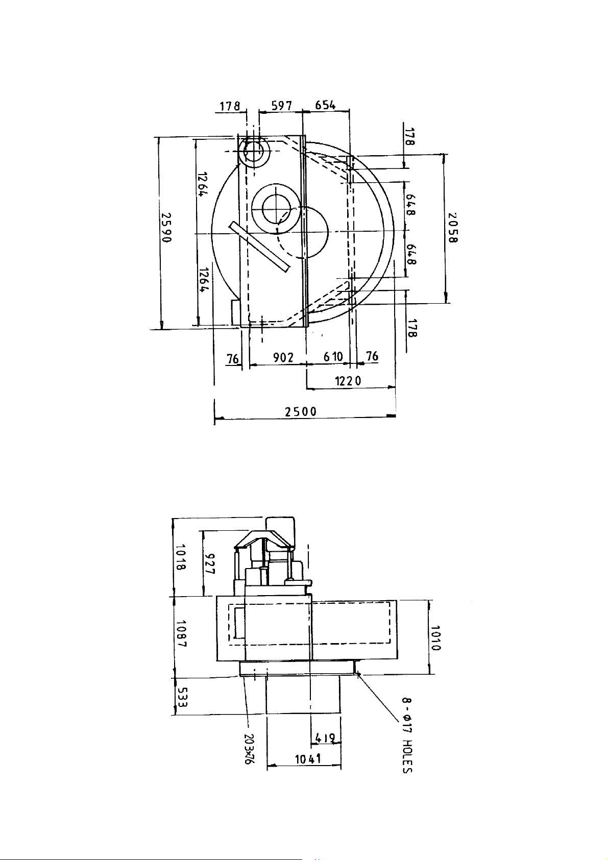
1.4 Installation Drawing
1.5 Test Certificates (Where applicable)
SECTION 2 INSTALLATION AND OPERATING INSTRUCTIONS
2.1. Pre Installation Notes
2.2. Installation Instructions
2.3. Operating Instructions
SECTION 3 TECHNICAL SPECIFICATION AND MAINTENANCE
3.1. Technical Specification
3.2. Shutdown Procedure and Maintenance
3.3. Maintenance of Mixer
3.4. Maintenance and Lubrication
3.5. Lubrication Layout
SECTION 4 MIXER SPARE PARTS
4.1. General Arrangement
4.2. Arrangement of Pan, Wear Plates, Pan Rollers and Pan Drive
4.3. Pan Support Roller Assembly
4.4. Pan Side Locating Roller Assembly
4.5. Pan Base, Side and Rack Arrangement
4.6. Star Drive Arrangement
4.7. Arrangement of Discharge Blade and Fixed Blade
4.4. Arrangement of Discharge Door & Pneumatic Cylinder
4.5. Layout of Guards
4.6. Pan Sealing Arrangement
4.7. Decals and Logos
SECTION 5 ANCILLIARY EQUIPMENT SPARE PARTS
5.1 Arrangement of Winch Unit
5.2 Arrangement of Loader Runway
5.3 Arrangement Loading Hopper
5.4 Arrangement of Split Shaft Whirler from S/No 6066
5.5 Arrangement of Split Shaft Whirler
5.6 Arrangement of Fixed Shaft Whirler

5.7 Arrangement of Weigher
5.8 Wire Rope Renewal Procedure
5.9 Wire Rope Safety Notes
5.10 180 Litre Water Tank
SECTION 6 ELECTRICAL SYSTEM
6.1 Electrical Instructions
6.2 Wiring Diagrams (Where applicable)
6.3 Component Listing (Where applicable)
6.4 Interlock Switch Mounting (Where applicable)
SECTION 7 PNEUMATIC SYSTEM
7.1 Pneumatic Instructions – Shutdown Procedure
7.2 Circuit Diagrams
SECTION 8 MISCELLEANEOUS
8.1 Noise
8.2 Special Pan Covers & Inlets
8.3 Miscellaneous Items
SECTION 9 ELECTRONIC LOADCELL & READOUT BOX
The contents of this handbook although correct at the time of publication, may be subject to
alteration by the manufacturers without notice and Winget Limited can accept no responsibility for
any errors or omissions contained within the following pages. Nor can we accept any liability
whatsoever arising from the use of this manual howsoever caused.
Winget Limited operate a policy of continuous product development. Therefore, some illustrations
or text within this publication may differ from your machine
Winget Limited can accept no responsibility for incorrectly supplied spare parts unless the part
number and a full description of the items required is given when the order is placed.
NOTE
Imperial fixings (bolts, setscrews, nuts, washers etc) have been progressively changed to Metric. If
in doubt as to whether you have a Metric or Imperial fixing please order the metric items listed, i.e.
bolt or setscrew and associated or flat and spring washers to replace the existing items
NOTE
Electrical cables particularly those with copper conductors suffer from a condition known as
‘relaxation’ which may cause wiring to work loose over a period of time, it is recommended
that the tightness of wiring connections and terminals are checked following the first month
in service.

OPERATING
AND
MAINTENANCE MANUAL
SECTION 1
GENERAL INFORMATION

COMPANY DETAILS AND GENERAL INFORMATION
For any spares or service work, please contact:-
Winget Limited
P.O. Box 41
Edgefold Industrial Estate
Plodder Lane
Bolton
Lancs U.K.
BL4 OLS
Telephone No: ++ 44 (0)1204 854650
Facsimile No: ++ 44 (0)1204 854663
‘E Mail’
crokersales@winget.co.uk
parts@winget.co.uk
service@winget.co.uk
ORDERING SPARES
To help us to complete your order promptly and correctly we need:-
• Machine type and serial number
• Description and quantity of parts required
• The full address to which the parts are to be sent
Winget Limited can accept no responsibility for incorrectly supplied spare parts unless the
part number and a full description of the items required is given when the order is placed.

The CUMFLOW RP1500XD is a high performance mixer
The following precautions are necessary to obtain the best results and to avoid
damage to the MIXING STAR and DRIVE
ENSURE TRANSIT BAR AND RING ARE REMOVED FROM DOOR
BEFORE STARTING MACHINE.
AGGREGATES
Strict control of graded aggregates must be maintained
Maximum size 38mm
Oversize lumps of aggregate or rogue materials must be prevented from
entering the Pan
IMPORTANT NOTICE
MIXING STAR BLADES
They are to a special shape and material to prolong w ear life. They should not
be modified in any way and only replaced with GENUINE ‘
Obtained from
WINGET LIMITED.
CROKER
’ spares
A daily check is advisable to ensure that the Blades/Wearing parts are secure
and undamaged.
PAN RIM & BASE WEARING PLATES
They must be replaced before excessive wear causes distortion.
MAXIMUM BATCH LOADS
UNDER NO CIRCUMSTANCES should the Maximum Batch Loads quoted
be exceeded nor should the mixer be or re-started when there is a mix in the
Pan
MIXING PAN
Ensure that the Mixing Pan is rotating concentrically and that the pan base is
Rotating in horizontal place, otherwise damage ma y occur to the door
mechanics.

WARNING
THE MANUFACTURER ACCEPTS NO RESPOSIBILITY FOR ANY
DAMAGE OR FAILURE RESULTING FROM OPERATIONAL
MISUSE OR MALPRACTICE. ANY MODIFICATIONS TO THE
MACHINE WILL AFFECT ITS WORKING PARAMETERS AND
SAFETY FACTORS. REFER TO THE MANUFACTURERS BEFORE
FITTING ANY NON STANDARD EQUIPMENT OR PARTS.
THE MANUFACTURERS ACCEPT NO RESPONSIBILITY FOR ANY
MODIFICATIONS MADE AFTER THE MACHINE HAS LEFT THE
FACTORY, UNLESS PREVIOUSLY AGREED IN WRITING. THE
MANUFACTURERS WILL ACCEPT NO LIABILITY FOR DAMAGE
TO PROPERTY, PERSONNEL OR THE MACHINE IF FAILURE IS
BROUGHT ABOUT DUE TO SUCH MODIFICATIONS, OR THE
FITMENT OF SPURIOUS PARTS.

RP1500XD
OPERATIONAL AND SAFETY
REQUIREMENTS
PRE-DELIVERY INSPECTION (Also see separate Document)
1.1 Drive coupling alignments, pan and star meshing of pan rack and drive gear.
1.2 Operating clearances star blade to pan. Fixed blade to pan wall.
1.3 D ischarge blade to pan base.
1.4 Rollers to register ring.
1.5 Correct oil level in gearboxes. All grease points charged. Gear teeth greased.
1.6 A ir system tested.
1.7 Door operation and seating.
1.8 No load test. Correct rotations.
PRE INSTALLATION
2.1 Check consignment.
2.2 Offload equipment using certified lifting gear of suitable capacity, by a competent
person (see separate chart for nett weight).
INSTALLATION
3.1
Refer to contract arrangement and site instructions.
3.2 Mixer to be mounted on supports of adequate strength and rigidity to prevent undue
vibration when mixing and securely bolted.
3.3 Mixer frame to be level on structure, add packers as required.
3.4 Check that pan is correctly seated on Rollers and that pan rack and drive gear are in
correct mesh.
3.5 Check locating rollers to register ring.
3.6 Check operating clearances star blade to pan. Fixed blade to pan wall. Discharge
blade to pan base. See maintenance section Ops Manual.

ELECTRICAL SERVICES
Refer to wiring diagram in Ops Manual. All wiring to be undertaken by competent
electrician.
NOTE:
electrical cables particularly those with copper conductors suffer from a
condition known as ‘relaxation’ which may cause wiring to work loose over a period of
time, it is recommended that the tightness of wiring connections and terminals are checked
following the first month in service.
4.1 Refer to pneumatic circuit diagram in Ops Manual. Connect compressor. Supply
compressed air 5.5 bars as required (80psi).
4.2 Refer to w iring diagram in Ops Manual when connecting air control valves.
4.3 Remove transit bar and ring from door BEFORE starting mixer.
4.4 E nsure starters are mounted away from mixer on supports free of vibration.
4.5 E nsure starters are fitted with correct overloads – see technical specification power
units.
OPERATION
5.1 Correct oil level, Gearboxes and Air line lubricator.
5.2 Mixing pan clear of loose nuts and bolts to prevent damage to fingers and blades.
5.3 Check correct rotation – mixing star – anti clockwise; mixing pan – anti clockwise.
All when viewed from the top.
5.4 D ischarge door and blade correct operation.
5.5 Blade operating clearances adjust in line with maintenance instructions.
5.6 Never exceed manufacturer’s m a ximum capacity as detailed in specification.
SHUTDOWN
6.1 Prior to any work being carried out mixer to be isolated and physically locked off.
Recommended equipment double key exchange system.
6.2 Follow procedure detailed in company and users’ Health and Safety Policy at
all times.
6.3 Ensure all storage bins containing materials to be mixed are isolated.

6.4
Shut off water supply and drain off water tank or flowmeter
MAINTENANCE
7.1 Ensure that all maintenance is carried out in accordance with the Parts and
Operating manuals and proprietary manufacturer’s specific instruction.
7.2 Isolate electrical and other services to the mixer as section 6 above.
7.3 Service at recommended intervals.
7.4 Use Croker manufactured replacement parts supplied by
WINGET LIMITED
GENERAL
8.1 Under no circumstances should the Maximum Batch Loads be exceeded by
either weight and volume as stated in Technical Specification.
8.2 Mixer star blades to be checked daily for damage.
8.3 Pan rim and base wearing plates must be replaced before excessive wear causes
distortion.
8.4 Ensure mixing pan is rotating concentrically and pan base is rotating in
horizontal plane.
8.5 Mixer must not be stopped and started when there is mix in the pan.
8.6 Refer to Contract Drawing for scope of supply. Site instruction notes outlining
weights etc.
.
8.7 Refer to Method Statement when installation and commissioning is
responsibility of Winget Limited.
Nett Weights Max (kgs)
9.1 R P50XD 788 RP1250XD 4840
RP100XD 814 RP1500XD 4980
RP200XD 1400 RP3000XD 7112
RP400XD 2000 FP1000 4040
RP550XD 2150 FP1500 4065
RP850XD 2600 FP2000 4100
9.2 Refer to technical specification for nett weights of ancillary equipment.
9.3 Refer to contract drawing for nett weights of ancillary equipment.

Miscellaneous
10.1 Noise measured in accordance with Directive 79/113 EE C 85LPA.
RP1500XD GENERAL ARRANGEMENT
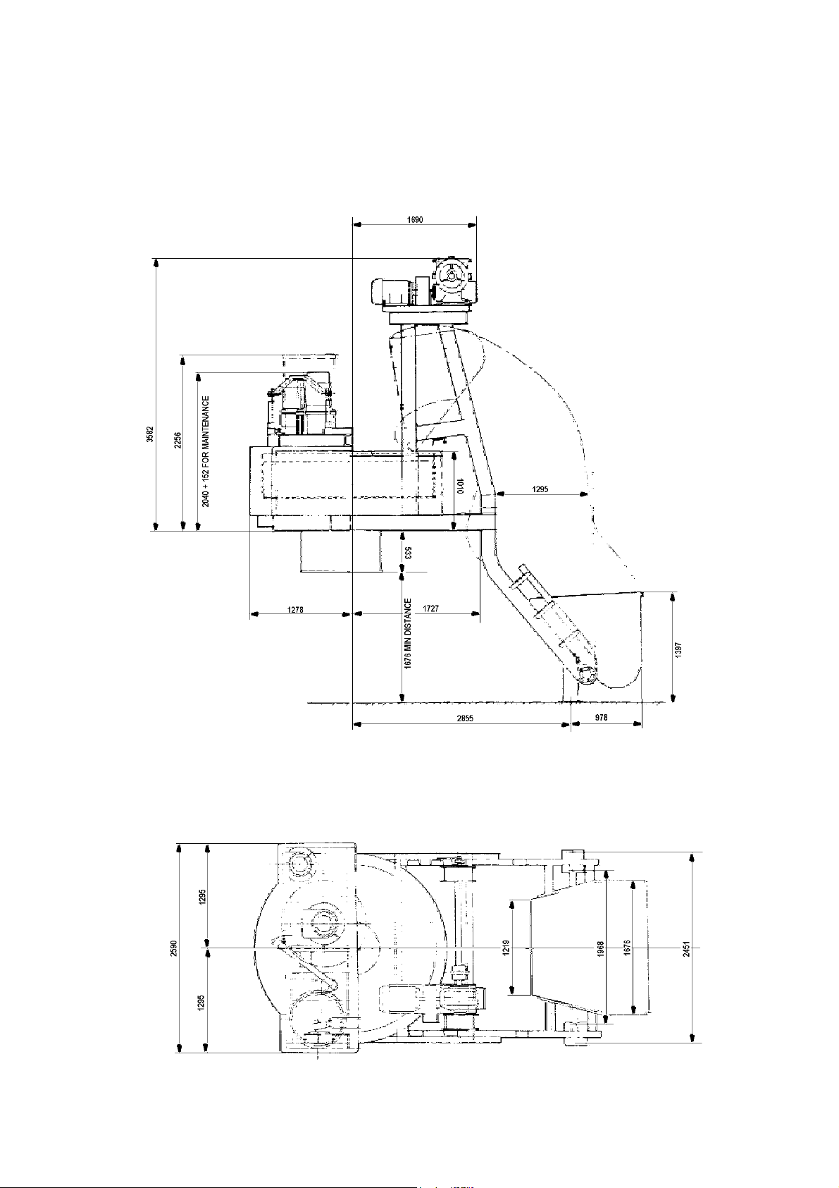
RP1500XD GENERAL ARRANGEMENT WITH
LOADER

INTENTIONALLY BLANK PAGE

OPERATING
AND
MAINTENANCE MANUAL
SECTION 2
INSTALLATION AND OPERATING
INSTRUCTIONS

PRE-INSTALLATION
On arrival of the equipment it is advisable to check that all packages listed on
the consignment note have been received.
The equipment must be offloaded using certified lifting gear of suitable
capacity, by a com petent person.
When unloading the mixer, care must be taken to ensure the discharge chute
remains clear of obstructions as the chute and door hang below the chassis.
An outline drawing and bolt hold plan is normally sent prior to the despatch of
the machine and will enable preparations to be ma de for the installation. With
the `picture` of what the machine will look like when it is assembled, the
ancillary equipment dismantled for transport can easily be identified.

INSTALLATION
Please refer to contract arrangement and site instructions as applicable.
It is recommended that a concrete foundation (to take foundation bolts – not
supplied) of at least 0.6m
2
by 0.3m thick to take M20 bolts should be provided
for each leg of the support structure and runway when fitted. When the machine
is supplied without a support structure it should be mounted on supports of
sufficient strength and rigidity to prevent undue vibration when the machine is
working. When making provision for a loading hopper pit it is strongly
recommended that the pit is concreted out so that it can easily be kept clean and
free from any build up which could prevent the bottom limit switch from
operating correctly.
Before completing the installation, check that the main mixer frame is level
with a spirit level. Packings should be inserted as required under the structure
legs or main frame. The packings under the mixing pan roller brackets are set
during manufacturing and must not be disturbed under any circumstances.
Check that the pan is seated and that the pan rack and drive gear are in mesh..
Also check that all the blade clearances are in line with the maintenance
instructions.
On connecting to the power supply, the wiring diagram must be referred to.
A check that the wiring is correct is the rotation of the following:-
• The mixing pan and mixing star rotate anti-clockwise when looking from
the top.
• The loader winch rotates anti-clockwise looking from the rope drum end
when the raise button is pressed.
• The whirler unit rotates clockwise when looking from the top.
It is advisable to mount the starters away from the machine on supports free
from vibration. Ensure that the starters are fitted with suitable overloads – see
technical specification – power units.
Note:- it is recommended that the
mains electrical supply is taken via an earth leakage circuit breaker.
A simple Water Flow Meter is available as an option to the water tank, this has
a range of 0-100 litres and features an adjustable flow indicator with a reset
facility allowing very accurate measurement of water flow irrespective of the
pressure. The Flow Meter is normally fitted with a manual ‘on/off’ valve and is
protected by a washable in line strainer.

A supply of compressed air at 5.5 bars is required. The inlet for the connection
from the air line is tapped ½” B.S.P. A drop in pressure will cause incorrect
operation of the pneumatic system.

OPERATING THE MACHINE
Before starting production the following points should checked:-
(1) That there is oil in (a) the Star Drive Gearbox
(b) the Pan Drive Gearbox
(c) the Loader Winch Gearbox (when fitted)
(d) the Air Line lubricator
(2) The Mixing pan should be clear of loose nuts, bolts, spanners etc., as
these will damage the fingers and blades.
(3) Check that the Discharge Door and Discharge Blade are operating
correctly.
(4) Check that the blade clearances are correct and if necessary adjust, in line
with the maintenance instructions.
(5) Check that the limit switches on the loader stop the Loading Hopper in
the required positions at the top and bottom of the runway.
(6) Check that the Water tank is set to the required amount and is filling up
to this level. (See later page for further information on Water Ta nk
operation).
(7) When Weigh Gear is fitted check that the setting arrangements and
lubrication requirements have been carried out.
(8) If a Flow Meter is fitted check that the pointer is reset to zero and the
strainer is clean and free from debris.
IMPORTANT:
The CUMFLOW is a high performance Mixer.
The following precautions are necessary to obtain the best results and to avoid
damage to the Mixing Star and Drive.
AGGREGATES:
Strict control of graded aggregates must be maintained. Maximum Size 38mm.
Oversize lumps of aggregate or rogue material must be prevented from entering
the Pan.

MIXING STAR BLADES:
They are of a special shape and material to prolong wear life. They should not
be modified in any way and only replaced by genuine ‘WINGET CROKER’
spares.
Daily check is advised to ensure that the Blades/Wearing Pieces are securely
bolted and undamaged.
PAN RIM & BASE WEARING PLATES:
They must be replaced before excessive wear causes distortion.
MAXIMUM BATCH LOADS:
Under no circumstances should the Maximum Batch Loads quoted be
exceeded nor should the Mixer be stopped and re-started when there is a mix in
the Pan.
After each mix the contents of the pan must be completely discharged
before attempting to close the discharge door. At the end of each period of
operation the mixing pan, mixing blades, discharge blade and fingers,
discharge chute, discharge door and seating must be washed down to
prevent concrete setting on them and so impairing the efficiency of the
machine.
WARNING:
THE MAUFACTURER ACCEPTS NO RESPONSIBILITY FOR ANY
DAMAGE OR FAILURE RESULTING FROM OPERATIONAL MISUSE OR MALPRACTICE.
OPERATING INSTRUCTIONS FOR WEIGH GEAR MECHANISM
HYDROSTATIC LOADCELL & GAUGE
The Hydrostatic Load Cell is connected by a flexible capillary tube (approx 9.7
metres long) to a 300mm (12”) diameter weigh gauge.
The whole system is assembled and filled with fluid under vacuum and under
no circumstances should any of the components be disconnected, in the event
of component damage the complete assembly should be returned to Winget
Limited for repair.

The system is factory calibrated and any variation between the calculated tare
and the actual tare recorded can be corrected by means of the tare adjustment
knob on the side of the gauge.
With no load acting on the loadcell the pointer will be below zero, this is to
accommodate the weight of the hopper. When the hopper is placed on to the
loadcell the pointer will register zero. Final zero adjustment can be made via
the zero adjustment knob on the side of the gauge housing.
ELECTRONIC LOADCELL & GAUGE
The electronic Loadcell & Gauge consists of an electrically operated loadcell
mounted on the weigher fram e and connected to a remote mounted digital
readout control box. The connecting lead should be protected from damage
and the readout box mounted such that it is not affected by vibrations etc. T he
mounting instructions detailed within Section 9 of this m anual should be
followed to avoid excess vibrations damaging the control box. Section 9 also
contains detailed advice on setting up, obtaining zero and operation of the
loadcell and readout box and should be referred to before the equipment is
operated.
NOTE THE FOLLOWING WIRING CONNECTIONS
+ Excite RED
- Excite BLUE
+ Signal GREEN
- Signal YELLOW
OPERATING INSTRUCTIONS FOR 0-100 LITRE
The simple manually operated 0-100 litre Water Flow Meter is available as an
option to the water tank and is normally mounted on the side of the mixer
feeding directly into the pan. The me ter is normally fitted with 1” hose tail
connectors but different sizes of water inlet connections to suit various hose
diameters are also available. The meter is normally provided with a simple
‘on/off’ valve and inline filter/strainer mounted next to but down stream of the
flowmeter.
WATER FLOWMETER
OPERATION
On a daily basis before use the strainer should be removed and checked for
debris and obstructions, cleaned and refitted. Ensure the on/off valve is in the
‘off ‘ position and turn on the main water supply. Set the adjustable pointer on
the dial face via the central knob to the required amount of water. Check the

indicator reads zero, if not operate the reset lever on the side of the meter which
will reset the indicator. Turn the on/off valve slowly to the ‘on’ position
watching the movement of the indicator around the dial, when the indicator
reaches the pointer sharply turn valve to the ‘off ‘ position. The indicator will
register the amount of water delivered. Operate the reset lever to bring the
indicator back to zero and repeat the operation for each batch of material
mixed.
When shutting down the mixer either at night or at the end of each shift it is
recommended that the main water supply to the flow meter and ‘on/off’ valve is
shut off.
If it is expected that the overnight temperatures will drop to or close to freezing
it is recommended that the Flow Meter, Valve, Filter and Pipework are drained
to prevent damage.

OPERATING THE MIXER
SAFETY NOTES
Never operate the mixer unless you have read and fully understand the contents
of the Operators Manual
Never operate the mixer whilst wearing loose fitting clothing
Never reach inside the Pan whilst it is rotating
Never operate any equipment unless you have received adequate training
Cement, certain other minerals and organic compounds can cause skin irritation
leading to Dermatitis. Always use Personal Protective Equipment i.e. gloves etc
to protect the skin from direct contact. If in any doubt about the materials being
used consult your employers COSHH manual
Wear Eye protection to protect your eyes from dust and liquid splashes
Do not attempt to remove the pan single handedly, obtain assistance, use the
Pan Trolley (if provided) or use suitable lifting equipment
Do not operate the mixer with any of the guards removed, safety devices or
interlocks disconnected. They are there to offer you some protection, ensure
they are correctly maintained
Carry out the daily maintenance before operating the mixer and report defects
to your supervisors
Oils, Greases and Lubricants are skin irritants and prolonged direct skin contact
can cause skin cancer. PPE or barrier creams should be used when carrying out
maintenance work, wash your hands on completion
Always dispose of waste oils and lubricants in a proper manner, it is illegal to
pour it down drains or bury it. Contact your local authority for a list of
authorised disposal sites
Always disconnect the power supply at the mains before carrying out any
maintenance work or cleaning the equipment down. Do not turn on the power
until everything has dried out
Do not allow waste from the wash down process to enter the public drainage
system unless it has been properly filtered.

Decals and Instruction Plates are attached to the equipment to warn against
hazards and assist in the safe operation of the equipment, if damaged or defaced
they should always be replaced.
It is likely that clutch and/or brake linings may contain asbestos and suitable
precautions should be taken to avoid breathing in the dust, protective clothing
should be worn. Hands should be washed immediately after handling
components and old discarded parts or linings should be disposed of in a
responsible manner in line with local or national regulations covering the
disposal of asbestos waste.

OPERATING
AND
MAINTENANCE MANUAL
SECTION 3
TECHNICAL SPECIFICATION
AND MAINTENANCE

TECHNICAL SPECIFICATION OF CUMFLOW RP1500XD
CAPACITIES: Maximum Batch Capacity by Weight 2290 kgs
by Volume 1500 litres
Nominal Output 1000 litres
(Based on 2200 kg/m
AGGREGATES: Maximum Aggregate Size 38 mm
MIXER FRAME: Strongly constructed from welded Steel Channel
MIXING PAN: Steel Base Pan mounted on three wide track rollers with central
discharge door. Pan Rim, Base and Discharge Door fitted with
renewable Wearing Plates available in different materials.
MIXING STAR: Tripple Arm Mounting, Six Spring loaded Star Blades, three at Pan
floor level and three for high level mixing.
FIXED BLADE: Spring loaded pan side scraper assembly.
3
)
DISCHARGE BLADE: Pneumatically operated in conjunction with the Discharge Door.
WHIRLER: Intermittent blades mounted on vertical shaft.
POWER UNITS: Mixing Star) 22 kw
Mixing Pan) 7.5 kw
Loader Motor (where fitted) 7.5 kw
Whirler Motor (where fitted) 15 kw
DRIVES Mixing Pan Gear unit with steel pinion and cast rack
Mixing Star Gear unit directly mounted
Whirler Vee Rope Drive
SPEEDS Speed of Pan 8.2 rpm
Speed of Mixing Star 44 rpm
Speed of Loading Hopper 21 metres/min
Speed of Whirler 720 rpm
FREE AIR CONSUMPTION (PER BATCH 80 PSI) 126.5 litres
WEIGHTS (UNLADEN) Without Loader 4980 kg
With Loader 5580 kg
ELECTRICS Motor Voltage 415V 3ph 50hz
Option 60Hz
Control Voltage 110V

MACHINE SAFETY DIRECTIVE
All Gears are suitably guarded.
MAINTENANCE
y
IMPORTANT
ALWAYS ENSURE APPARATUS IS ISOLATED FROM MAINS SUPPLY
BEFORE COMMENCING MAINTENANCE.
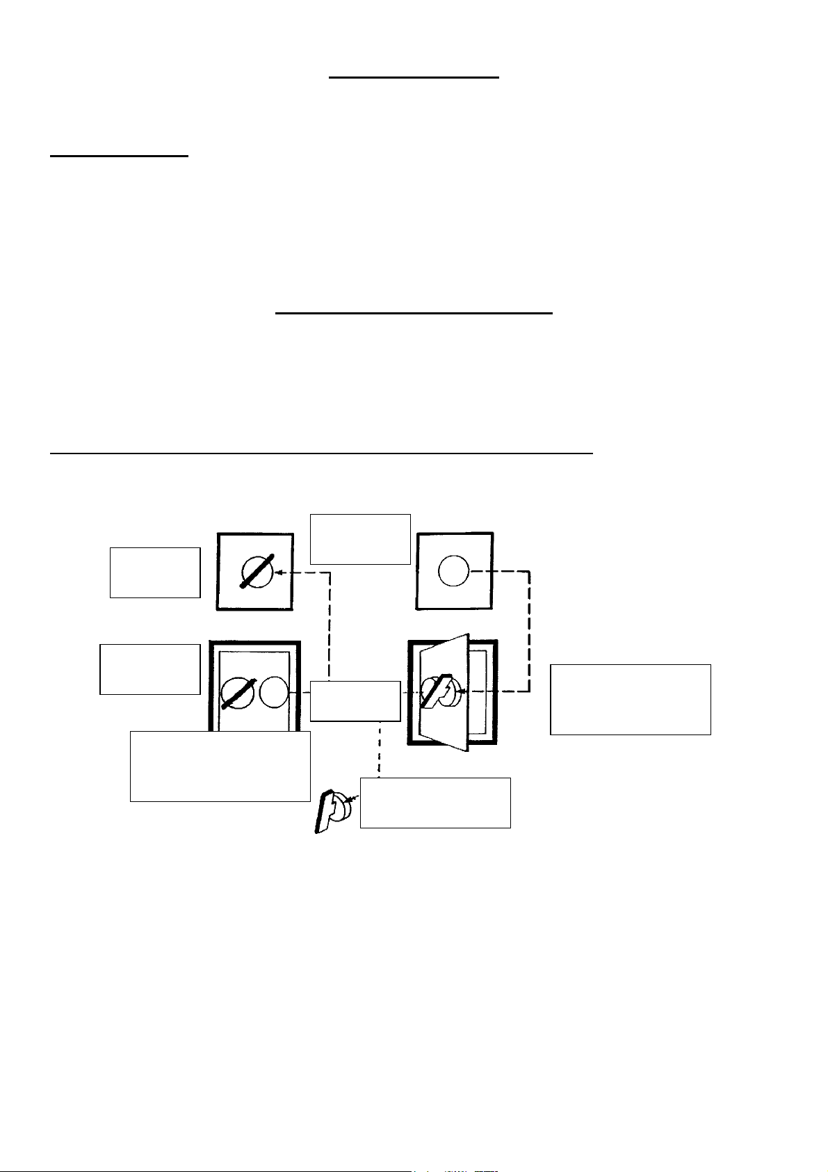
SHUTDOWN PROCEDURE
Prior to any work being carried out the apparatus is to be isolated and physically locked off.
We recommend a double key exchange system.
Safe access to equipment with one access door and one control point.
Supply Locked
Off Key Free
Supply on
Key Trapped
Door Locked
Key Trapped
Equipment Working Supply
On Access Door Locked
Door Open
Ke
Trapped
Supply Locked Off Key
Free
Equipment Stopped Supply
Locked Off Access Door
Open
Follow the procedures detailed in your Health and Safety Policy at all times.
Ensure all storage bins containing materials to be mixed are isolated.
Shut down the water supply and drain off any water tanks or flowmeter fitted

MAINTENANCE OF MIXER
IMPORTANT NOTE:
Ensure that all maintenance is carried out in accordance with the Parts and Operating
Manual and Proprietary Manufacturer’s specific instruction.
PROCEDURE
1 ISOLATE ELECTRICAL, PNEUMATIC AND OTHER SERVICES TO THE
MIXER (see separate section).
2 Service at recommended intervals.
3 Use Croker manufactured replacement parts available from
WINGET LIMITED
4 Ensure all safety guards and interlocks are reinstated prior to operating the mixer
5 Main items of wear (see Section 4).
A) Star Blades
B) Fixed Blade
C) Discharge Blade
D) Whirler Blades
Access to mixing pan internals is via the safety interlocks. Each of the above are
bolted components and are replaced by simple method and usually achieved in situ
without dismantling other com ponents.
E) Pan base and rim wearing plates are also bolted construction and can be
replaced in situ. However, pan covers will need to be dismantled to provide the
necessary access.
.
.
F) Other items prone to less wear are star blade fingers, lower whirler shaft
assembly and mixing star. Each can be replaced again in situ but pan covers
would require tensing to provide necessary access.
G) Pan rollers can be adjusted to accommodate wear during operation. These can
be replaced when required in situ using jacking method to support pan and
provide the necessary access.

MAINTENANCE AND LUBRICATION
DAILY: Using Total Multis EP2 grease (or equivalent) and grease the following
points:-
Pan Roller Spindles 3 Points
Pan Locating Rollers 4 Points
Discharge Blade Lifting Gear Brackets 2 Points
Air Cylinder Lever Pivot Holder 1 Point
Mixing Blade Finger Bearings 3 Points
Fixed Blade Finger Bearing 1 Point
Loading Hopper Rollers 2 Points
Inspect and top-up if necessary:-
Air Line Lubricator Use Total Azolla 27 (or equivalent)
Or suitable Pneumatic Tool Oil
WEEKLY: Inspect and top up if necessary:-
(1) Star Drive Gearbox Use Total Carter EP320 (or equivalent)
(2) Pan Drive Gear Box Use Total Carter EP320 (or equivalent)
(3) Loader Winch Gearbox (Flender) Use Total Carter EP220 (or equivalent)
Inspect and Adjust
(1) Pan Gear and Pinion – Apply Open Gear Lubricant (or equivalent) as required.
(2) Adjust Star Blades, Fixed Blades and Discharge Blade to the following settings, also
make sure that Blade fingers are free in their bearings and that the springs are clear of
obstructions.
Mixing Blade: (3 mm) clear of pan base. Adjust by moving the blade down
its finger.
Discharge Blade: Just touching pan base when finger bridge is resting on stop
sleeves. Adjust by moving bridge up or down fingers.
Fixed Blade: (3 mm) clear of pan base and just touching pan rim. Adjust
by moving hinge brackets along its slots and blade up or
down its fingers. Re-set spring to 100 mm overall length
after setting blade.
(3) After the first week’s running the Whirler Vee Belt Drive will need adjustment to take
up initial wear/stretch. At the correct tension it should be just possible to twist each
belt through 90
o
when gripped between finger and thumb midway between pulleys.
 Loading...