

Page 1
300R & 400R
WORKSHOP MANUAL
WINGET LIMITED
PO BOX 41
EDGEFOLD INDUSTRIAL ESTATE
PLODER LANE
BOLTON
LANCS
BL4 0LS
Tel:-++ 44 (0) 1204 854650
Fax:- ++ 44 (0) 1204 854663
www.winget.co.uk
ISSUE 8 2012
Page 2

WORKSHOP MANUAL
300R 400R
WINGET REVERSING DRUM CONCRETE MIXERS
ISSUE 8 2012
CONTENTS
Section 1 Introduction
Section 2 Repair and Service Procedures
Section 3 General Arrangement Dimensions
Section 4 Service Schedules
Lubrication Diagram
Section 5 Hydraulic Circuit Diagrams
Section 6 Wiring Diagrams
Section 7 Noise Levels
Section 8 Special Tools
Section 9 Hydraulic Control Valve
Service Manual (Where available)
Section 10 Parts Listings
Section 11 Batchweigher Maintenance Instructions
Section 12 Reversing Gearbox Manual
Section 13-18 Blank
IMPORTANT Engine Change
From mid 2004 the Lister Petter TS2 and TS3 engines were replaced by the Lister Petter
TR2 and TR3 engines. The TR range of engines is completely interchangeable with the
TS range and consumable items such as filter elements are identical. There are some
internal component differences and when ordering spares it is important to state whether
it is a TS or TR engine.
Instructions and notes found throughout this manual which refer to TS engines are also
applicable to the TR engine
Ref: SHSC1216
Page 3

WORKSHOP MANUAL
300R & 400R
SECTION 1
INTRODUCTION
Page 4

WORKSHOP MANUAL
300R 400R
WINGET REVERSING DRUM CONCRETE MIXERS
ISSUE 8 2012
Introduction
The following procedures should enable experienced service personnel to strip, repair
and rebuild Winget 300R and 400R Reversing Drum Concrete Mixers in a safe and
competent manner. The procedures are not intended to be used by personnel who are
unfamiliar with the product nor mechanically inexperienced.
It is assumed that personnel are aware of Health and Safety Regulations which should
be applied to all working practices, but the following should act as a reminder.
Ensure all work tools are in good condition.
Always wear Safety Spectacles when using Soft or Hard Faced Hammers, Chisels or
when using Air Tools. Wear Safety Spectacles when cleaning hardened concrete or
mortar off components.
Do not misuse Air Lines and be aware of the damage Compressed Air can cause if
misused.
Always make sure lifting equipment is in good condition and the Safe Working load
exceeds the weight of the components to be lifted.
Oils, Fuels, Silicone Sealers and Open Gear Lubricants can cause skin diseases if
allowed to contaminate the skin. Always apply barrier creams, wear suitable protective
clothing, or when contamination is unavoidable clean the area with soap and water as
soon as possible. Do not use thinners or other solvents to clean skin.
Health and Safety is a matter of common sense. If common sense is applied correctly
Health and Safety can be improved and the risk of accidents reduced.
Refer to the Parts Listings in Section 10 or the Parts & Operators Manual for a guide to
the correct sequence for assembling components and sub assemblies.
It is assumed for the purposes of this manual that the machine is standing on firm level
ground and is horizontal in both planes.
Left hand and Right Hand views are taken when looking directly at the Feed Hopper.
Whilst every effort is made to ensure the contents of this manual are accurate Winget
Limited accept no responsibility for errors or omissions and reserve the right to alter
specification without prior notification in which case certain sections may then no longer
apply.
Ref: SHSC1216
Page 5

WORKSHOP MANUAL
300R & 400R
SECTION 2
REPAIR & SERVICE
PROCEDURES
Page 6

WORKSHOP MANUAL
300R 400R
WINGET REVERSING DRUM CONCRETE MIXERS
ISSUE 8 2012
Lifting Points
Lifting Points capable of supporting the weight of the Mixer are incorporated in both of
the Water Tank Supports just below the height of the Drum Top Guard.
The Lifting Points are highlighted with an ISO ‘Hook’ symbol adjacent to each Point.
On Military/Nato mixers the Lifting Points are also painted white.
The Hopper also incorporates Lifting Points to assist in removing the Hopper. The L/H
Point is used to secure the Hopper Safety Chain which is attached to the raised Hopper
during maintenance work. The Hopper Lifting Points are not highlighted to avoid
confusion with the main lifting points. On no account must the Hopper Lifting Points be
used to support the weight of the mixer.
Drawbars – Standard & Military/Nato
The Drawbars are retained to the Front axle by two ‘L’ shaped retaining pins which are in
turn secured by two lynch pins c/w chains which are inserted through the retaining pins
once the drawbar is in position. To remove the drawbar first remove the lynch pins,
withdraw the retaining pins and lift the drawbar clear, refit the retaining pins and prevent
their loss by refitting the lynch pins. Reverse the procedure to refit the drawbar.
Military/Nato Towing Eye (Used with Military/Nato Drawbars)
Remove the split pin, castle nut and flat washer retaining the eye in the drawbar.
Remove the eye. To refit reverse the above procedure, do not fully tighten the nut, allow
the eye to rotate in the drawbar. New eyes will require drilling for the split pin when fitted
in place.
Jack Legs
To remove a Jack Leg either jack up and support the machine or using suitable lifting
equipment lift the machine. Pull out the retaining pin remove the leg. Refit in the
reverse order.
Military/Nato machines have an additional security measure in the form of a lynch pin
through the jack leg retaining pin to prevent the jack leg dropping unintentionally.
Ref: SHSC1216
Page 7

WORKSHOP MANUAL
300R 400R
WINGET REVERSING DRUM CONCRETE MIXERS
ISSUE 8 2012
Anti-Bounce Bracket
An Anti-Bounce Bracket is fitted between the L/H side of the Hopper Cradle and
Mainframe whilst transporting the mixer to prevent the Hopper bouncing and causing
damage to the Batchweigher Loadcell and other components.
One end of the Hopper Anti-Bounce Bracket is bolted to the Hopper Cradle, the other
end is retained by the Jack Leg retaining pin.
To remove the Hopper Anti-Bounce Bracket, start the engine and raise the Hopper very
slightly to release its weight off the bolt and jack leg retaining pin (it is normal for the
Hopper to settle slightly during transportation).
Remove the bolt, pull out the pin and lift the Anti-Bounce Bracket clear. Refit in the
reverse order.
On no account must attempts be made to fully raise the Hopper whilst the Anti-Bounce
Bracket is in place.
Pneumatic Wheels, Stub Axles, Hubs
The complete Wheel, Stub axle and Hub assemblies are retained to the axles by four
bolts, two positioned vertically and two horizontally. To remove the assemblies, support
the machine on the jack legs, remove the bolts and lift the assemblies clear. If fitted take
care not to lose the tapered washers. Reverse the procedure to refit.
Wheels – Pneumatic
To change a wheel, first slacken the five nyloc nuts, jack up the machine supporting the
weight on a jack leg. Remove the nuts and wheel. To refit, reverse the procedure.
Hubs
Remove the wheel as described previously. Knock off the dust cap. Remove the split
pin and nut, pull off the hub assembly complete with bearings and oil seal. Knock out
the bearings and oil seal clean the hub and shaft. Pack the new bearings with grease.
Fit the new bearings and oil seal into the hub. Coat the shaft with copperslip, push the
hub complete with bearings onto the shaft. Fit the flat washer and castle nut and tighten
the nut. Back off until the wheel spins freely with no end float. Align the nut with the
cross drillings in the shaft, fit the split pin. Refit the wheel as described previously.
Steel Wheels, Stub Axles and Hubs
To remove the complete assembly refer to Pneumatic Wheels, Stub axles and Hubs.
Ref: SHSC1216
Page 8

WORKSHOP MANUAL
300R 400R
WINGET REVERSING DRUM CONCRETE MIXERS
ISSUE 8 2012
Wheels – Steel
Steel wheels are retained to simple stub axles using a collar retained by a single cross
bolt. To remove the wheel, jack up the machine, remove the bolt, remove the collar and
lift the steel wheel clear. Reverse the procedure to refit coating the shaft, bore of he
steel wheel and collar with copperslip.
Front Axle and Pivot Bracket
To remove the axle or pivot bracket, support the front of the machine and fully raise the
jack legs. Remove the drawbar, stub axles, hubs and wheel assemblies as described
previously. Remove the split pins and washers retaining the tie bar between the axle and
mainframe, support the axle and remove the tie bar, remove the split pins, and washers
though the pivot pin, knock out the pin. Remove the supports and lift the axle clear of
the pivot bracket. The pivot bracket may be held in place by either a split pin and
washer or nut and bolt. Reassemble in the reverse order coating pins etc. with
copperslip, replacing damaged split pins.
Water Tank Removal (Where fitted)
Turn off and disconnect the water supply. Remove the split pin and disconnect the
operating rod. Unbolt and remove the outlet pipe. Unbolt the tank and using suitable
lifting equipment lift the tank clear of the mainframe. Refit in the reverse order.
For an explanation of the Water Tank operation and repair instructions see page 29.
Flowmeter Removal (Where fitted)
The Flowmeter is mounted on a bracket on the L/H side of the mainframe and is
connected to the inlet pipe at the drum charge mouth by a 1.5 bore rubber hose. The
meter is a mechanical device featuring a reset facility and includes a water on/off valve
and an inline strainer which is removable for cleaning. To Remove the Meter disconnect
the rubber hose by either slackening one of the hose clamps or removing one of the
threaded connectors, remove the two ‘U’ bolts securing the meter in place and lift the
meter clear. Reverse the procedure to refit. Note:- the meter itself contains no user
serviceable components.
Drum Edge Rollers
Where fitted remove the water tank as previously described. Support the front of the
drum to prevent it falling forward suddenly when the Edge Roller assembly is removed.
Release the adjusting screw then unbolt and remove the edge roller assembly taking
care not to lose the shim packers. Remove the setscrews holding the rollers into the
housing and remove the rollers. Support the rollers in a soft jawed vice remove the
Ref: SHSC1216
Page 9

WORKSHOP MANUAL
300R 400R
WINGET REVERSING DRUM CONCRETE MIXERS
ISSUE 8 2012
circlips and using a suitable drift, knock the shafts through the bearings and out of the
rollers. Drift the bearings out of the rollers. Using a sharp instrument remove the seals
from the new bearings and pack the bearings with clean good quality grease, replace the
seals.
Reassemble in reverse order taking care not to forget the ‘V’ seals. When assembling
the rollers back into the housing do not fully tighten the setscrews until the assembly has
been refitted and final adjustment carried out.
Refit the assembly onto the drum housing. Adjust the height of the assembly using the
shims so the rollers do not foul the drum circumference and the drum gear ring will not
foul the assembly.
Adjust the rollers against the track ring so that a total 1.5mm clearance exists between
the rollers and ring. Tighten the setscrews. Lock the adjusting screws with locking wire.
Note:
Incorrectly setting the rollers in relation to the track ring will result in premature bearing
failure and/or excessive wear of the track ring and idler rollers.
As a final check that all adjustments are correct remove the support from below the
drum, engage either forward or reverse drive and crank the engine rotating the drum
checking visually that neither a foul condition nor tight rollers exist.
If removed refit the water tank assembly.
Drum Removal
It is necessary to remove the Drum for replacement of the Drum Gear Ring it is also
strongly recommended that the Drum is removed if repair or replacement of the Idler
Rollers is necessary.
Remove either the Water Tank or Flowmeter and Water Inlet Pipe and Drum Edge
Rollers as described previously.
On machines fitted with a Dragline remove the Mast and Cable. Disconnect the Wire
Rope from the Shovel and wind back onto the Winch Motor. Mark for identification
purposes the hoses to the Winch Motor and disconnect both the hoses from the Motor.
Fit blanking caps and plugs to both the hoses and Winch motor adaptors to prevent the
ingress of foreign matter. Disconnect the Electrical Cable and using suitable lifting
equipment support the Dragline Winch Motor Bracket, remove the retaining setscrews
and nuts and lift the assembly clear. Where a Batchweigher is fitted unbolt the Gauge
from the left hand Water Tank Support and stow in the Mainframe (Do not disconnect
the small bore pipe).
Ref: SHSC1216
Page 10

WORKSHOP MANUAL
300R 400R
WINGET REVERSING DRUM CONCRETE MIXERS
ISSUE 8 2012
Release the Engine/Fuel Tank Cover from the Right Hand Water Tank Support, if a UK
step is fitted, separate the top step from the rest of the step assembly.
Unbolt both Water Tank Supports and lift clear using suitable lifting equipment.
Unbolt and lift off the Drum Top Guard.
Attach suitable lifting gear to the Drum Assembly (The Drum weighs approximately ¾
tonne when clean) and lift out of the Mainframe. It may be necessary to remove the
Drum Mouth Extension to allow attachment of the lifting equipment.
Reassemble in reverse order, following the instructions for adjusting the Drum Edge
Rollers.
Drum Gear
Remove the Drum as described previously. Stand the Drum Assembly on the charge
mouth. Remove the Socket Headed Capscrews securing the Gear to the Drum. Using
suitable lifting equipment lift the Gear clear of the Drum.
Drum Cone Extensions
The various mouth extensions either Standard Steel Cone, Steel Extension Cone or
Rubber Extension Cone bolt to the Drum mouth. Removal is simply a matter of
removing the ring of bolts and lifting off the mouth extensions.
Drum Blades
Drum Blades can be changed with the Drum in Situ. The Blades are bolted in place and
if the Drum interior is clean replacement is fairly straightforward although two pairs of
hands are necessary. Unbolt and discard the old Blades and bolt the new Blades in
their place using new bolts.
Take care if using oxyacetylene cutting equipment to remove corroded bolts for the
concrete can “explode” violently spitting pieces of concrete. Wear suitable safety
goggles or spectacles. Do not breathe in the fumes generated by the cutting or burning
process, ensure the drum is well ventilated and wear suitable air fed breathing
apparatus.
Idler Roller Non Drive R/H
Whilst it is recommended that the Drum is removed to enable the Rollers Assemblies to
be replaced It is possible to remove the Rollers with the Drum in situ provided care is
taken.
Remove the Water Tank or Flowmeter and the Edge Rollers as described previously.
Ref: SHSC1216
Page 11

WORKSHOP MANUAL
300R 400R
WINGET REVERSING DRUM CONCRETE MIXERS
ISSUE 8 2012
Remove the Inspection Covers from each side of the Drum Housing. Block up the Drum
taking the weight off the Roller Assemblies or support the weight of the Drum using
suitable lifting equipment.
Remove the Stop Bar, unbolt the Rear Carrier Bracket, remove the nuts and washers
from the bolts securing the Front Carrier Bracket but do not remove the bolts which are
supporting the Front Bracket and preventing the complete assembly dropping into the
Drum Housing.
Carefully manoeuvre the Roller Assembly through the access hole, the assembly is quite
heavy and extra hands or suitable lifting equipment are recommended. Take care not to
lose the Shim Pack.
Remove the bolt securing the Rear Carrier and the grubscrew securing the Front Carrier
remove both from the shaft.
Remove the eight setscrews holding the Oil Seal Housing/Bearing Retainer to each side
of the Roller.
Support the Roller and using a suitable soft faced hammer knock the shaft and bearings
out of the Roller. Secure the shaft in a soft jawed vice and remove the bearings off the
Shaft. Using a sharp instrument remove the seals from the new bearings and pack the
bearings with clean good quality grease, replace the seals.
Fit a new Bearing to the longer front shank of the Shaft and using a suitable bearing tube
seat the Bearing and Shaft in the front of the Roller (small diameter) until the Bearing is
flush with the face of the Roller. Fit a new Oil Seal to the Bearing Retainer and secure in
place on the Front of the Roller. Turn the roller over. Using a suitable bearing tube fit
the Rear Bearing to the shaft and into the Roller until the Bearing is flush with the face of
the Roller. Fit a new Oil Seal to the Bearing Retainer and secure to the Roller.
Refit the Front and Rear Carrier Brackets. Using suitable lifting equipment, lift the Roller
Assembly back into the Mainframe, loosely secure the front Carrier to the Mainframe
with the four nuts, bolts and washers. Insert the Shim pack under the Rear Carrier and
Shim the Roller and Shaft until it is horizontal.
Place a straight edge across the rear face of the Roller and ensure it is square with the
opposite roller. Tighten the retaining bolts. Refit the stop bar. Remove the Drum
supports and lower the Drum back onto the rollers.
Refit the Edge Rollers and Water Tank or Flowmeter as described previously. Run the
mixer, checking operation of the Drum. Coat the Rollers/Gear with open gear lubricant.
Stop the engine. Replace the inspection covers.
Ref: SHSC1216
Page 12

WORKSHOP MANUAL
300R 400R
WINGET REVERSING DRUM CONCRETE MIXERS
ISSUE 8 2012
Idler Roller/Drum Drive Pinion L/H
Whilst it is recommended that the Drum is removed to enable the Roller Assemblies to
be replaced it is possible to remove the Rollers and Drum Drive Shaft with the Drum in
situ provided care is taken.
Remove the Water Tank or Flowmeter and the Drum Edge Rollers as described
previously. Remove the Inspection Covers from each side of the Drum Housing. Block
up the Drum taking the weight off the Roller Assemblies or support the weight of the
Drum using suitable lifting equipment.
Remove the Chain Cover, Drive Chain and Upper Sprocket as described on page 11.
Remove the Stop Bar, unbolt the Plummer Block and Bearing Assembly, remove the
nuts securing the front Bearing Carrier/Housing but do not remove the bolts which are
supporting this housing and preventing the complete assembly dropping into the Drum
Housing.
Carefully manoeuvre the Roller Assembly through the access hole, the assembly is very
heavy and it is recommended that either an additional pair of hands or suitable lifting
equipment are used. Take care not to lose the shimpack.
Remove the Grub Screw and remove the Plummer Block and Bearing off the rear of the
Shaft. Remove the Front Bearing Carrier/Housing off the shaft and retrieve the spacer.
Using a soft faced hammer knock the cast Drive Pinion off the shaft, remove the Parallel
Key and “V” Seal.
Following the procedure for the R/H Idler Roller, strip and rebuild the Roller Shaft and
Bearing. Not forgetting to remove the seals from the new bearings and pack the
bearings with clean good quality grease and replace the seals.
Refit the Plummer Block and Bearing to the rear of the Shaft lock the Grubscrew.
Fit the “V” Seal and Parallel Key to the shaft. Slide home the cast Drive Pinion and
spacer. Clean all traces of silicone sealer from the front Bearing Housing/Carrier and
Mainframe mating surfaces. Refit the Housing to the Shaft. Apply a bead of silicone to
the housing face.
Lift the Roller Assembly back into the Mainframe loosely securing the front
Carrier/Housing. Insert the Shim Pack below the Plummer Block and Bearing shim the
Roller and Shaft until it is horizontal.
Place a straight edge across the rear face of the Roller and ensure it is square with the
opposite roller. Tighten the retaining bolts. Refit the Stop Bar.
Refit the Upper Drive Sprocket, Drive Chain and Chain Cover as described previously.
Remove the Drum supports and lower the Drum back onto the Rollers.
Ref: SHSC1216
Page 13

WORKSHOP MANUAL
300R 400R
WINGET REVERSING DRUM CONCRETE MIXERS
ISSUE 8 2012
Refit the Edge Rollers and Water Tank or Flowmeter as described previously. Run the
mixer, check the operation of the Drum coating the Rollers/Gear with open gear
lubricant. Stop the engine and replace the inspection covers.
Drive Chain Adjustment
The Drive Chain is located behind the cast cover on the front of the Mainframe. The
cover contains an inspection aperture through which the Chain Tension can be checked.
The Tension is correct when the chain deflects 8mm-12mm mid way between the
sprockets.
To adjust the chain, remove the Inspection cover on the L/H side of the Drum Housing.
Slacken the three nuts on the lower Bearing Bracket, do not slacken the nuts too much
to avoid oil leaks following chain adjustment. Using the adjusting screw above the
Bearing Bracket increase or decrease tension on the chain as necessary. Lock up the
nuts. Replace the Inspection Covers.
Drive Chain/Sprocket Replacement
Drain the oil from the Chain case. Remove the setscrews and lift the Cast Chain Cover
from the Mainframe. The joint between the Chain Cover and Backplate/Mainframe is
made with Silicone Sealer and the Cover may require gently prising from the Mainframe.
Slacken the Adjustable Bearing Bracket as previously described to release the Chain
Tension. Disconnect the Chain split link and remove the Chain.
To remove the upper sprocket cut the locking wire, remove the special screws and
retaining washer, pull of the sprocket. Take care not to lose the key. In some cases it
may be necessary to use a suitable two legged puller.
To remove the Lower Sprocket remove the Circlip and Grubscrew. Pull off the sprocket
taking care not to lose the key. In some cases it may be necessary to use a suitable two
legged puller.
Reassemble in the reverse order taking care when refitting the lower sprocket that the
shaft is not moved backwards.
Re-tension the Chain as previously described on page 10.
Ensure the joint faces on the Cover and Backplate are clean. Apply a generous bead of
Silicone Sealer to the Cover, allow the sealer to cure for a few minutes then refit the
Covers.
Top up the oil through the inspection aperture and refit the cover plate.
Ref: SHSC1216
Page 14

WORKSHOP MANUAL
300R 400R
WINGET REVERSING DRUM CONCRETE MIXERS
ISSUE 8 2012
Start the engine, running the drive train checking for unusual noises.
Adjustable Bearing Bracket/Lower Drive Shaft
Remove the Chain Cover, Drive Chain and Lower Sprocket as described above.
Remove the L/H inspection cover, disconnect the Propshaft between the Gearbox and
Lowe Drive Shaft. Release the adjusting screw above the Bearing Bracket remove the
nuts from the three studs securing the Bracket and carefully pull off the Bearing Bracket
taking care not to damage the gasket. If damaged the gasket must be replaced.
The Bearing Bracket is sealed to the Mainframe using a thick gasket which is coated
with silicone sealer on assembly. Clean all traces of jointing materials from the
Mainframe and Bearing Bracket.
Remove the Drive Shaft from the Bracket, pull the Thrust Washer and “V” Seal of the
shaft. Using a suitable Bearing tube and a soft faced hammer knock the Needle Roller
Bearings out of the Bracket.
Reassemble the Bearing Bracket assembly fitting new bearings, place the Thrust
Washer and “V” Seal on the Shaft. lubricate the shaft and push the Shaft home into the
Bracket. Ensure the mating surfaces of the Bracket and Mainframe are clean and apply
Silicone Sealer to both surfaces, allow the Silicone to cure for a short time then apply the
gasket to the Bracket and apply a bead of Silicone Sealer to the gasket. Take care when
fitting the Bracket not to damage the gasket. Refit the Propshaft.
Following the procedures described previously fit the Lower Sprocket, Drive Chain and
Chain Cover. Take care when adjusting the chain not to damage the gasket. Top up the
Chain Case oil and refit the inspection cover.
Chain Case Back Plate
Remove the Chain Cover, Drive Chain, Upper and Lower Sprockets, Propshaft and
Adjustable Bearing Bracket as previously described. Remove the nuts securing the
three lower studs into the Back plate. Remove the four nuts, bolts and washers securing
the Upper Drive Shaft Bearing Carrier to the Mainframe and Back plate.
Prise off the Back plate and remove all traces of old sealing compounds from the
Mainframe, Back plate and Bearing Bracket. If a new Back plate is to be fitted change
over the three studs.
Apply a generous bead of silicone sealer to the rear face of the Back plate paying
particular attention to the various holes in the Back plate. Allow the silicone to cure
slightly then refit the Back plate. Once in place it is important that the Back plate is
disturbed as little as possible throughout the reassembly stage to avoid oil leaks when
the Chain Case is refilled with oil.
Ref: SHSC1216
Page 15

WORKSHOP MANUAL
300R 400R
WINGET REVERSING DRUM CONCRETE MIXERS
ISSUE 8 2012
Refit the Adjustable Bearing Bracket, proposhafts, Lower and Upper Sprockets not
forgetting the bolts securing the Bearing Carrier Drive Chain and Chain Cover.
Top up with oil, run, test the mixer and check for oil leaks.
Drum and Gearbox Controls
Hand Lever
The Hand lever pivot is retained on the inside of the Drum Housing with a split pin and
washer, removal of the Hand lever will allow replacement of the pivot bushes, (which
should be reamed to size following replacement) and the Roller and Bush.
Slotted Operating Lever
The Slotted Lever is retained to its pivot via a circlip and flat washer. To renew either
the Lever or its Bushing remove the Handlever as previously described, disconnect the
Connecting Rod, remove the Circlip and Washer, pull off the Lever. If the Bushing is
renewed it will require reaming to size.
Reassemble in reverse order.
Connecting Rod
Disconnect the Spherical Bearing at the end of the Connecting Rod from the Slotted
Lever, remove the locknut and adjusting nut from the other end of the rod. Carefully pull
the Rod through the Long Sliding Gland, Clevis Block, Spring, Sleeve and Short Sliding
Gland. Remove the second adjusting nut and locknut. Remove the Spherical Bearing.
Reassemble in the reverse order.
Drum Clutch Adjustment
Set the Handlever in the Mix/Charge position and rotate the nut on the Connecting rod to
allow 3mm of the Short Sliding gland to protrude beyond the end of the Clevis Assembly,
lock up the locking nut.
Repeat this operation in the Discharge position and rotate the nut on the Connecting
Rod to allow 3mm of the Long Sliding gland to protrude beyond the end of the Clevis
Assembly, lock up the locking nut.
Gearbox Removal
Disconnect the Connecting Rod as previously described.
Disconnect and plug the pipework and fittings at the Hydraulic Pump. Split the Driveshaft
between the Engine and Gearbox at either the Twiflex or toothed drive coupling. Unbolt the
Ref: SHSC1216
Page 16

WORKSHOP MANUAL
300R 400R
WINGET REVERSING DRUM CONCRETE MIXERS
ISSUE 8 2012
Gearbox from the Mainframe, using suitable slings and lifting equipment lift the Gearbox
clear of the Mainframe .
Reassemble in reverse order ensuring the centreline of the Engine and Gearbox are in
line by shimming as necessary to avoid straining the Couplings and Flanges.
Engine Removal
On Electrical Start Diesel and machines fitted with a Dragline and Alternator, isolate the
Battery and disconnect the wiring. Split the Driveshaft between the Engine and Gearbox
at either the Twiflex or toothed drive coupling. Unbolt the Engine from the Mainframe,
disconnect the Air Cleaner pipework. Using suitable lifting equipment lift the Engine clear
taking care not to lose the two engine packers. (Note later ‘CE’ machines are fitted with
guarding over the propshaft.)
Reassemble in the reverse order ensuring the centreline of the Engine and Gearbox are
in line by shimming as necessary to avoid straining the Couplings and Flanges.
Air Filter
The Air Filter is located on the Engine/Fuel Tank Shroud on the R/H side of the mixer.
During operation dust collected the body is ejected through the rubber valve in the side
of the filters cylindrical body. The Element, which should be removed daily for cleaning
and replaced at least once every 300 hours or three months is retained in the main body
by a large wing nut, which when released allows removal of the element for cleaning.
Hydraulic Tank
The Hydraulic Tank contains a Suction Filter suspended below the Tank Lid. To access,
clean any debris from the top of the tank, disconnect the Hydraulic Pipework from the
Tank Lid, plug all hoses and blank off all fittings, remove the screws and carefully lift off
the Lid to avoid damaging the lid seal. Unscrew and clean the filter.
Reassemble in reverse order ensuring the seal between the Lid and Tank Body is in
good condition.
Oil Draining
The oil drain plug is located centrally in the base of the Hydraulic Tank and can be
accessed from below the machine.
To drain the oil run the engine and circulate the oil through the system until warm. Stop
the engine and remove the Tank Lid as described above. Place a collection tray below
the Tank, remove the plug and allow the Tank to drain completely. Clean out the Tank
and refit the drain plug. Refit the Lid. Top up the oil until the oil is level with the tip of the
cone at the base of the oil filler neck. Run the engine, operate the Hopper and Dragline
Ref: SHSC1216
Page 17

WORKSHOP MANUAL
300R 400R
WINGET REVERSING DRUM CONCRETE MIXERS
ISSUE 8 2012
Controls. Stop the engine and allow the oil in the Tank to settle for approximately two
minutes before rechecking the level.
Note:
The Hydraulic Systems holds approximately 22 Litres (5 gallons) of oil.
Located on the top of the tank is the Bleed Valve which allows oil discharged from the
single Acting Hopper Ram (as the Ram lowers the Hopper) to bleed back into the tank.
If replacing the Bleed Valve body, ensure that the Ball in the Body forms a good seat by
driving the Ball down on the seat using a soft faced punch.
The tank is retained in the Mainframe by three M10 setscrews, however it is not possible
to remove the Tank unless the Gearbox is first removed.
Hydraulic Pump
The Hydraulic Pump is located on top of the Gearbox secured by four setscrews and is
driven through the Gearbox Bevel Gears, via a Pump Mounted Bevel Pinion. If replacing
a Bevel Pinion on the pump be aware that many pumps have more than one keyway cut
into the tapered shaft, selecting the wrong keyway will result in premature shearing of
the key.
Hydraulic pumps should be shimmed to give 5-8 Thou (0.02-0.20mm) gear backlash.
Place the Pump Assembly onto the Gearbox without any shims and measure the gap
between the pump body and gearbox casting. Add 5-8 thou (0.02-0.20mm) to the
measurement obtained and select the correct number of shims.
Hydraulic Control Valve
The Hydraulic Control Valve is mounted on the L/H side of the machine below the step
being secured to its bracket by at least two bolts, nits and washers.
Lifting the control lever raises the Hopper whilst lowering the lever lowers the Hopper.
The Control Valve powers the Single Acting Hydraulic Ram and also provides oil for the
Dragline Winch Motor via a High Pressure Carryover located in one of the control valves
ports. The adjustable system relief valve is located in the Control Valve and apart from a
spool seal kit no and handle kit no other user serviceable parts are available.
Ref: SHSC1216
Page 18

WORKSHOP MANUAL
300R 400R
WINGET REVERSING DRUM CONCRETE MIXERS
ISSUE 8 2012
Hopper Ram & Restrictor
Lift the Hopper and support with the Safety Chain provided.
Disconnect the ¼ bore hose leading from the Header Tank to the Ram cylinder and plug
the hose to prevent oil loss. Remove the bolt retaining the Upper Pivot Pin through the
Hopper Cradle and knock out the pin. Do not lose the Washers placed each side of the
Ram Eye. Allow the ram to drop forward, the upper eye bush is now visible and can be
replaced if necessary. When replacing the upper bush with the ram in situ it is important
that the ram is prevented from moving from side to side. When fitting a new bush ensure
the lubrication hole in the bush is aligned with the grease nipple.
To remove the Ram Assembly, disconnect and plug the Hydraulic Hose and the
Restrictor on the Ram port. Remove the bolt retaining the lower pivot pin through the
Mainframe. Support the Ram with suitable lifting equipment and knock out the lower pin.
Lift the Ram Assembly clear drain out any oil and support in a suitable soft jawed vice.
Clean the area around the end cap and attaching a suitable tool unscrew the end cap,
carefully remove the rod and piston assembly and secure in a soft jawed vice.
Examine the cylinder bore carefully for signs of scoring or corrosion and the piston rod
for signs of pitting or peeling, it is pointless attempting to reseal a ram which has a
damaged bore or rod.
Remove the split pin securing the Piston Nut and remove the Nut, Piston Assembly and
End Cap. Remove and discard the old seals, new seals should be soaked in clean
hydraulic oil before fitment. Ensure all components are clean. Fit the new seals, rebuild
the Ram in reverse order fitting a new split pin through the piston retaining nut.
The Restrictor screwed into the Ram Inlet/Outlet port restricts the flow of oil out of the
Ram as the Ram is closed ensuring a more controlled descent.
The Restrictor contains a spring and Poppet valve and does not usually cause problems
in service.
Note:
The Hydraulic Ram is single Acting and in operation when the Ram is closed the
majority of the Hydraulic Oil is discharged from the full bore side of the Ram. To avoid
condensation forming in the annulus (upper) side of the cylinder as the Ram is closed,
oil is drawn into the annulus side from the Header Tank to fill the void with oil, this oil is
expelled back into the Header Tank as the Piston raises extending the Ram and lifting
the Hopper.
The Header Tank contains a sight glass and it is important that the oil level within the
Tank is checked on a daily basis. The oil level is correct if it is just visible in the sight
glass when the ram is fully closed.
Ref: SHSC1216
Page 19

WORKSHOP MANUAL
300R 400R
WINGET REVERSING DRUM CONCRETE MIXERS
ISSUE 8 2012
Hose Failure Valve
Machines bearing the “CE” mark indicating compliance with the EC Machinery Safety
Directive have a Hose Failure Valve fitted to the Ram Inlet/Outlet port in addition to the
restrictor.
In service it is not unusual for violent operation of the Control Valve (In order to shake
material free from the Hopper when the Ram is at the full extent of its stroke) to blow off
the relief valve activating the Hose Failure Valve. Which then prevents closing of the
Ram and lowering of the Hopper.
Should this occur, slowly lift the Hopper slightly by extending the Ram without blowing
off the relief valve, then slowly close the Ram lowering the Hopper. Once the Hopper
has lowered by approximately 300mm normal operation can be resumed.
If a new hose failure valve is to be fitted the valve should first be unscrewed from the
body, and the gap between the valve baffles adjusted to 2mm by means of the small
capscrew and nut. Following adjustment, the valve should be screwed fully home into
the body and operation of the machine checked when it is fitted.
Hopper, Cradle, Link Arms and Pivot Shaft
Link Arms
The Hopper Cradle pivots on Needle Bearings contained within the “L” shaped Link
Arms.
To remove the Arms lower the Hopper Cradle and block up the Hopper to prevent the
assembly dropping when a Link Arm is removed.
Remove the Bearing Caps, each secured with three setscrews which pass through the
Caps and Arms into the Bearing Housings. Remove the Nut and Flat Washer retaining
the Link Arm to the Shaft, pull off the Arm, retrieve the Housings and “O” Rings from the
Pivot Shafts.
Remove the Inner Bearing of the Shafts, using a suitable bearing tube and soft faced
hammer remove the Outer Bearings from the Link Arm.
Reassemble in the reverse order greasing the Needle Bearings on Assembly.
Hopper Cradle and Hopper
Removal
Raise the Hopper slightly to allow access to the Hopper retaining bolts and nuts, attach
suitable lifting equipment to the Hopper, remove the bolts and carefully lift the Hopper
clear.
Ref: SHSC1216
Page 20

WORKSHOP MANUAL
300R 400R
WINGET REVERSING DRUM CONCRETE MIXERS
ISSUE 8 2012
Attach the lifting equipment to the Hopper Cradle, raise the Cradle to allow removal of
the upper Ram pivot pin, lower the Cradle. Remove both Link Arms and the Link Shaft
which passes through the Cradle, lift the Hopper Cradle clear.
Reassemble in reverse order.
Pivot Shaft
The Pivot Shaft is retained in the “A” frame by two grubscrews one each end of the
Shaft.
To remove the Shaft carry out the procedures describing removal of the Hopper, Link
Arms and Cradle. Remove the Inner Bearings from the ends of the Shaft. Remove the
grubscrews and using a soft faced hammer knock out the Shaft.
Reassemble in reverse order coating the Shaft with copperslip and ensuring the Shaft is
central in the “A” frame before tightening the Grubscrews.
Batchweigher
The Batch Weigher Gauge is located on the L/H Water Tank Support and is mounted on
rubbers to dampen vibrations. The Gauge is connected to the Loadcell which is located
in the Mainframe below the Hopper Cradle via a hydraulic pipe.
The Loadcell and Gauge must be considered a sealed unit and on no account must the
hydraulic pipe be removed.
Damage to the Gauge or Loadcell is most commonly caused by dropping a loaded
Hopper onto the Loadcell, allowing an empty Hopper to free fall directly onto the
Loadcell or filling the Hopper directly from a Site Dumper, Skid Steer Loader, Tipping
Lorry or other similar equipment.
These cause high shock loadings which can loosen the Needle Pointer in the Gauge,
damage the Loadcell seals, or cause the top half of the Loadcell to turn over at an angle.
Although the both Workshop Manual and the Operators Manual contains instructions for
overhauling the unit, it is recommended that the Loadcell and Gauge Assembly are
returned to Winget Limited whenever possible for repairs. Field service and repairs can
often cause complications and accurate calibration of the Assembly cannot be
guaranteed. Winget Limited can accept no responsibility should attempts be made to
overhaul or repair the units.
Assuming the Loadcell and Gauge are in good condition the most common causes of
inaccurate weighing are:-
1) Mixer not level
Ref: SHSC1216
Page 21

WORKSHOP MANUAL
300R 400R
WINGET REVERSING DRUM CONCRETE MIXERS
ISSUE 8 2012
2) Hopper resting on ground or build up of waste material below Hopper. Ensure at
least 50mm (2”) clearance between the ground and Hopper.
3) Build up of material around the Hopper Cradle Link Shaft.
4) Worn Hopper Cradle Pivot Bearings.
5) Loadcell Striker guide fouling Mainframe or failing to rotate freely.
6) Worn Loadcell Striker Pin.
7) Failure to Re-Zero Batchweigher Gauge by means of the Zeroing knob on the
side of the Batchweigher Gauge.
Batchweigher Adjustment
Should the Batchweigher require adjustment the following procedure should be carried
out.
With the Loadcell Striker resting on the Loadcell, check the top of the Link Arms are
horizontal to within 2-3mm, and the Link Shaft is clear of the holes on the Cradle, if not,
adjust the packing below the loadcell.
Check the Loadcell Striker is resting centrally on the Loadcell button, if not, slacken the
setscrew below the Loadcell and adjust its position, or slacken the grubscrews securing
the Hopper Cradle Pivot Shaft to the “A” frame and move the assembly over. Tighten
the screws following adjustment.
Check the Loadcell Striker is at approximately 25 degrees to the Hopper Cradle, if not,
adjust by altering the Loadcell Striker packing between the Striker and Hopper Cradle.
Place known weights in the Hopper to check the Gauge reading progressively
throughout its range.
To increase the Gauge reading at low loads, increase the amount of packing below the
Loadcell.
To increase the Gauge reading at high loads, increase the amount of packing behind the
Striker.
Loadcell Striker Guide
The Loadcell Striker Guide is mounted in the Mainframe just behind the Loadcell, and
rotates on Needle Roller Bearings.
To remove the Guide, raise and support the Hopper. From inside the Mainframe remove
the grubscrew retaining the Guide Pivot Pin. Knock out the Pin and Lift the guide clear.
Prise out the Seals and using a suitable bearing tube and soft faced hammer remove the
Needle Roller Bearings.
Ref: SHSC1216
Page 22

WORKSHOP MANUAL
300R 400R
WINGET REVERSING DRUM CONCRETE MIXERS
ISSUE 8 2012
Reassemble in reverse order coating the Pivot Pin with copperslip, and ensuring the
Guide rotates freely and does not foul either side of the Mainframe.
Feed Apron
Two or Three Compartment Feed Aprons are designed to assist the flow of materials
into the Hopper in conjunction with a Dragline.
The Feed Aprons consist of L/H and R/H side panels, Base Panel, Centre Dividers (one
or two depending on the option chosen) Support Bar, Rubber Flap, (to prevent materials
falling between the Hopper and Apron) and Rubber Retainer.
To assemble the Feed apron, place the Base smooth side up in front of the Hopper, lay
the Rubber Flap on the Base and secure with the Retainer and countersunk screws.
Using a suitable support raise the Base so that the Rubber is approximately 520
millimetres (1’8”) off the ground and the Base slopes back at an angle, bolt both Side
panels in place. Remove the support so the weight of the Base is taken by the side
Panels. Fit the Support Bar between the Side Panels and bolt the Centre Dividers in
place.
Check that the Rubber Flap projects slightly out over the Hopper Mouth and that both
are in line, stake the Feed Apron securely in place using the four picketing lugs, two on
each Side Panel.
The Feed Apron can be extended backwards to separate aggregate by fitting boards into
the ends of the Side Panels and Centre Dividers.
Dragline Electrical System
Two different electrical systems or method of power generation are utilised depending
on the engine or electric motor fitted.
Hand Start Lister-Petter TS & Electric Motor
When a Hand Start Engine or Electric Motor are fitted, the Gearbox drives via a “V” belt
a 12 volt automotive type Alternator. This is in turn connected via 2 core cable to a Panel
Mounted Isolator Switch and Warning Light. A Battery (acting as a storage device for
the Alternators output) mounted on the R/H side of the mainframe, through a Two Pin
Plug and Socket to the Shovel Mounted Operating Button/Switch and on to the Dragline
Solenoid Valve.
The most common causes of electrical failure are:-
1) Break in the two core cable between the Shovel mounted Button/Switch and the
Socket and Plug mounted below the Winch Motor. (If the Cable is shortened do
not reduce the length to less than 19.8 metres, 65 feet).
Ref: SHSC1216
Page 23

WORKSHOP MANUAL
300R 400R
WINGET REVERSING DRUM CONCRETE MIXERS
ISSUE 8 2012
2) Dirty or loose electrical connections at the Plug and Socket, at the Solenoid
Valve, at the Alternator or Battery.
3) Bad Earth Connections.
4) Worn or badly adjusted “V” Belt.
5) Worn or dirty Alternator Brushes.
6) Failure to turn on the Isolator Switch before starting the Engine or Motor.
7) Flat Battery.
Voltage/Setting Instructions
It is not possible to adjust the Voltage Setting but the voltage can best be measured at
the Terminal Block on the Solenoid Valve.
Remove the Terminal Block, Connect a D.C. Voltmeter to the Terminal Block, operate
the Isolator Switch and start the Engine or Motor. Depress the Shovel mounted
Button/witch and note the voltage reading, it should not exceed 14.5 volts. If the
Voltmeter indicates a negative reading or reads in the reverse direction interchange the
Voltmeter leads.
Electric Start Lister-Petter TS
When an Electric Start Engine is fitted the Charging System built into the Engine
provides the electrical power to operate the Dragline Solenoid Valve.
Power is taken from Terminal 2 on the Ignition Switch, through 2 core cable via a Plug
and Socket through the Shovel Mounted Operating Button/Switch, back through the Plug
and Socket down to the Dragline Solenoid Valve (See Wiring Diagram).
The most common causes of electrical failure are:-
1) Break in the two core cable between the Shovel Mounted Button/Switch and the
Socket and Plug mounted below the Winch Motor (If the cable is shortened do
not reduce the length to less than 19.8 metres, 65 feet).
2) Ignition Switch in the “Off” position.
3) Dirty or loose electrical connections at the Plug and Socket, the Solenoid Valve,
Ignition Switch or Battery.
4) Flat Battery.
5) Charging System Failure (See Engine Workshop Manual).
6) Bad Earth Connections.
Voltage Setting Instructions
It is not possible to adjust the Voltage Setting but the voltage can best be measured at
the Terminal Block on the Solenoid Valve.
Ref: SHSC1216
Page 24

WORKSHOP MANUAL
300R 400R
WINGET REVERSING DRUM CONCRETE MIXERS
ISSUE 8 2012
Remove the Terminal Block, Connect a D.C. Voltmeter to the Terminal Block and start
the engine. Depress the Shovel mounted Button/witch and note the voltage reading it
should not exceed 14.5 volts. If the Voltmeter indicates a negative reading or reads in
the reverse direction interchange the Voltmeter leads.
Dragline Winch Motor
The Dragline Winch Motor is mounted on a bracket which is supported across the Water
Tank supports, the hydraulic motor itself contains no user serviceable parts and should
be replaced in the event of failure. The motor and winch drum are protected by a
removable cover which is retained by two setscrews and nuts.
Four replaceable Nylon or Steel Rollers are mounted directly in front of the Winch Motor
and allow the Wire Rope to operate without damage. The Rollers are retained by long
through bolts and self locking nuts which are removed to allow replacement of the
rollers. NOTE:- The position of the rollers can be alternated to even up the wear on them
and prolong their service life.
Operation of the Winch Motor is controlled by the Shovel Mounted Button/Switch via the
Solenoid and Dragline Control Valves.
When correctly piped up the Winch Motor rotates in a Clockwise Direction to pull the
Dragline Shovel in and freewheels in an Anti-clockwise Direction when the Dragline
Shovel is being pulled out by the Operator.
If the hoses to the Winch Motor are disconnected they should be marked to aid
identification and both the hose ends and fittings in the Motor plugged to prevent the
ingress of dirt or foreign matter. The Dragline Winch Motor circuit is protected by a
secondary ‘relief valve’ contained in the Dragline Control Block.
Refer to the Dragline Hydraulic System Description on Page 26 for further information.
Dragline Control Block
The Dragline Control Block is mounted onto and above the Solenoid Valve, and in
conjunction with the Solenoid controls the hydraulic oil flow to the Winch Motor.
The Control Block contains no internal user serviceable components apart from a simple
Relief Valve, the setting of which is altered by adding or removing Shim Washers to
increase or decrease the Spring Setting which in turn increases or decreases the
hydraulic pressure to the Dragline Motor.
Refer to the Hydraulic System Description for additional information.
Ref: SHSC1216
Page 25

WORKSHOP MANUAL
300R 400R
WINGET REVERSING DRUM CONCRETE MIXERS
ISSUE 8 2012
Dragline Solenoid Valve
The Dragline Solenoid Valve contains no user serviceable parts, and if checks of the
electrical system indicate it is faulty it must be replaced.
Oil leaks between the Valve and Control Block indicate the failure of the small ‘O’ rings
which can be replaced following removal of the Solenoid Valve which is retained by four
socket headed capscrews.
Refer to the Hydraulic System Description for additional information.
Hydraulic System Description
The Basic Hydraulic System is simple in design consisting of a gearbox mounted
Hydraulic Pump, Main Hydraulic Tank onto which is mounted the Bleed Valve, the tank
also contains the Suction Strainer. A Header Tank connected to the annulus side (full
bore or upper) of the Hopper Ram with a drain hose to the main hydraulic tank. A Single
Spool Control Valve and Single Acting Hydraulic Cylinder onto which the Flow Restrictor
and Hose Failure Valve are also fitted. The Hose Failure Valves are only fitted to those
machines intended for use within the European Community.
The Pump is driven by the gearbox drawing oil from the Tank through the Suction
Strainer. The Pump delivers the oil to the Control Valve, if the Valve Control Lever is in
the neutral position the oil is directed back to the tank through the tank return line.
(When a Dragline is fitted the threaded adaptor on the tank is fitted with an additional
Tee piece to allow for extra return lines)
When the Control Lever is raised to lift the Hopper, the Valve Spool directs the oil
through the tank mounted Bleed Valve down to the Ram where it passes through the
Hose Failure Valve (where fitted) and Flow Restrictor before operating the Cylinder.
The tank mounted Bleed Valve is designed to ensure that when the Hopper is fully
lowered, no residual pressure remains in the circuit between the Cylinder and Control
Valve which could affect the Batchweigher readings. The Bleed Valve contains a Ball
and Spring and is ported to allow oil to flow back into the tank. Oil flowing under
pressure from the Control Valve to the Cylinder enters the top of the Bleed Valve and
acts on the Ball which is depressed against spring pressure closing off the Tank Port
thus directing oil to the base of the Cylinder.
If the Control Lever is returned to neutral during the lift or lowering cycle, the pressure
created in the circuit between the Cylinder and Control Valve by the weight of the
Hopper acting on the Cylinder, is sufficient to hold the Ball on the seat within the Bleed
valve, preventing the Hopper from dropping. (Should the Hopper continue to drop the
Ball/Seat within the Bleed Valve possibly requires attention).
Ref: SHSC1216
Page 26

WORKSHOP MANUAL
300R 400R
WINGET REVERSING DRUM CONCRETE MIXERS
ISSUE 8 2012
If the Control Lever is operated to lower the Hopper, the weight of the Hopper displaces
oil out of the Cylinder, pressure in the circuit is not sufficient to retain the Ball on its seat
and oil returns to the tank via both the Bleed Valve and Control Valve.
When the Hopper is fully lowered the residual pressure in the pipework between the
Control Valve and Cylinder is dispersed through the Bleed Valve, allowing the Hopper’s
weight to act fully onto the Batchweigher Loadcell.
The Header Tank connected to the annulus side of the Single Acting Ram is designed to
ensure the cylinder is always full of oil preventing changes in climatic conditions causing
the formation of damaging condensation. The oil level in the Tank can be checked on a
daily basis when the Hopper is lowered via the sight glass built into the face of the Tank.
The level is correct when it is just visible in the sight glass, should the tank be overfilled
the excess oil will be returned to the Main Tank via the overflow/return pipe.
In service it is expected that over time oil under pressure will migrate from the full bore
side of the cylinder into the annulus side, passing the piston seals as they wear. This
migration will increase the level of oil in the Header Tank whilst at the same time
lowering the oil level slightly in the Main Tank, once the oil in the Header Tank reaches a
certain level the excess will return via the return/overflow pipe to the Main Tank.
Excessive topping up of the Header Tank may cause an increase in the oil level within
the Main Tank, levels should be monitored on a regular basis and the levels reduced if
necessary.
Dragline Hydraulic System
The Dragline Hydraulic System consists of a 12 Volt Solenoid Controlled Oil Distribution
Block (otherwise known as the Dragline Control Block) containing an adjustable Relief
Valve. A Hydraulic Motor is fitted to operate the Dragline Winch. The system is
continuously supplied with oil whilst the engine is running via a High Pressure Carryover
at the Main Control Valve.
When the 12 volt Solenoid is not energised, oil flow from the Main Control Valve is
directed by the Distribution Block direct back to the hydraulic tank through the centre
return line which terminates on the tank lid/cover. The supply and return hoses supplying
oil to the Winch Motor from the Distribution Block are at the same time ported within the
Block to form a closed loop enabling the Winch Motor to revolve freely with minimum
resistance when the Dragline Shovel is manually pulled backwards by the operator.
When the 12 volt Solenoid is energised by operating the Shovel Button/Switch, the tank
return is closed, the loop is opened and oil is directed to the Winch Motor which revolves
reeling in the Dragline Shovel. Oil exiting the Winch Motor is returned to the Distribution
Block where it is directed down the second return line through the tank mounted tee
piece, back into the tank.
Ref: SHSC1216
Page 27

WORKSHOP MANUAL
300R 400R
WINGET REVERSING DRUM CONCRETE MIXERS
ISSUE 8 2012
Should for any reason the Motor jam or seize in operation the Relief Valve in the
Distribution Block should “Blow off” dumping the oil down the return line via the tee piece
back into the tank.
Relief Valve Adjustment
Main Relief Valve
With the Engine or Electric Motor at rest and the Hopper fully lowered ensure no residual
pressure remains in the hydraulic system by operating the hydraulic control lever a
number of times. Check and top up the hydraulic oil level.
Disconnect the supply hose to the top of the Bleed Valve, attach a suitable tee piece to
the Bleed Valve and reconnect the hose. Connect a Hydraulic Pressure Gauge to the
tee piece. The gauge should preferably be a minimum of 75mm in diameter with a
minimum scale reading of 3500 psi and should be attached to a length of two wire
hydraulic hose C/W crimped adaptors which is long enough to reach to the operator’s
station by the Control Valve.
Start the Engine or Motor and allow to run until the oil is warm. Operate the Control
Valve raising the Hopper to its maximum height until the relief valve ‘blows off’ note the
maximum pressure recorded on the gauge, it should read 2000 psi (138 BAR) If the
reading is higher or lower the Relief Valve requires adjusting. Lower the Hopper, stop
the Engine or Motor and disperse any residual pressure as described above. If the Hose
Failure Valve has ‘locked out’ the Ram follow the procedures described on page 17 to
release.
Slacken the Relief Valve locking nut (some valves may be protected by a removable
cap) and identify whether the Valve is adjusted by means of a screwdriver or hexagon
key.
Start the Engine or Motor and raise the Hopper again to momentarily ‘blow off’ off the
relief valve, noting the reading, release the Control Valve Lever to neutral and adjust the
relief valve either clockwise or anti clockwise dependant on whether the pressure
requires increasing or decreasing. Do not turn the valve more than ¼ turn each time an
adjustment is made, after each adjustment ‘blow off’ the relief valve noting the pressure
obtained until the correct pressure is recorded.
Lower the Hopper, stop the Engine or Motor, disperse any residual pressure and remove
the gauge, hose and tee piece. Reconnect the supply hose directly to the Bleed Valve,
clean up any oil spills and check the oil level within the tank. Top up if necessary.
Dragline Relief Valve
Check the Main System oil pressure as described above. Disperse any residual oil
pressure. Identify and disconnect at the Dragline Control Block the feed hose from the
Dragline Control Block upto the Winch Motor, plug the open end of the hose. Attach to
the Dragline Control Block in place of the hose removed the hydraulic test gauge c/w
Ref: SHSC1216
Page 28

WORKSHOP MANUAL
300R 400R
WINGET REVERSING DRUM CONCRETE MIXERS
ISSUE 8 2012
with length of hose but without the tee piece, this will form a ‘dead head’ within the circuit
as the oil can go no further than the gauge.
Operate the Dragline Isolator Switch (handstart and electric machines only). Start the
Engine or Motor, there should be no need to allow the oil to warm up as it should still be
warm from the previous tests, momentarily depress the Switch /Button on the Dragline
Shovel to ‘blow off’ the relief valve and note the reading on the gauge. Do not unduly
hold down the Switch/Button, only depress long enough to obtain a reading then release
otherwise a steep increase in oil temperatures will be experienced and damage may be
caused to the hydraulic system.
The gauge should read a maximum of 1500psi (103BAR), to adjust stop the Engine or
Motor and disperse any residual pressure. Identify the large hexagon on the side of the
Dragline Control Block which is the head of the relief valve and carefully unscrew,
withdraw the hexagon which incorporates the spring guide, the bonded seal, spring and
poppet valve. Small flat washers are placed on to the spring guide to increase the
tension on the spring thereby increasing the pressure, removing a washer will reduce the
pressure. During initial manufacture one washer is placed on to the spring guide and this
is usually sufficient but over time in service the spring may weaken and require
additional washers adding. Add or subtract a washer as may be necessary, refit the
relief valve assembly and repeat the procedures described above to recheck the
pressure.
Failure to attain the required pressure may indicate a worn or sticking poppet valve or
worn seat.
Water Tank Description
The Tank is designed to automatically shut off the flow of incoming water once the
desired measured quantity (between 10-75 litres/2-16 Gallons) is achieved.
Mounted on the front of the Tank Body is a Graduated Scale and Carrier, passing
through the Carrier is a Pointer and Pivot Pin. Once the Pointer is set to the required
amount on the Scale the Pointer and Scale Carrier are locked together with a wing nut
and coach bolt.
Both the Scale Carrier and Pointer Pivot Pin pass into the interior of the Tank where the
Scale Carrier terminates in a Cam, the Pointer Pivot Pin carries the Float Arm and
Plastic Float Assembly and terminates at the Operating Lever.
Moving the Pointer along the Graduated Scale effectively raises and lowers the height of
the Float Assembly in the Tank.
Mounted on the outer L/H side of the Tank adjacent to the Scale Carrier is the Water
Inlet containing the Water Strainer. Attached to the Water Inlet on the inner face of the
Tank is the Water Inlet Valve assembly.
Ref: SHSC1216
Page 29
Page 30

WORKSHOP MANUAL
300R 400R
WINGET REVERSING DRUM CONCRETE MIXERS
ISSUE 8 2012
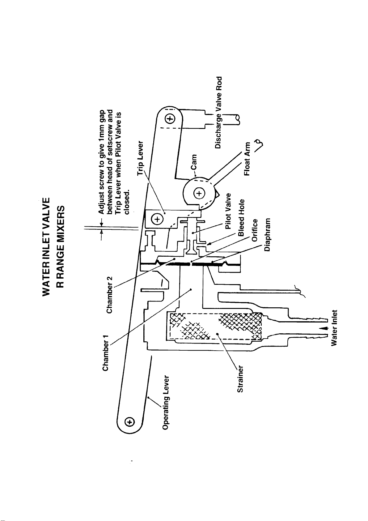
The Water Inlet Valve consists of a Body and Cover sandwiching a Brass and Rubber
Diaphragm. The Cover is machined to carry the sprung Pilot Valve.
Water enters the Valve Body through the Strainer filling the chamber acting on the rear
rubber face of the Diaphragm, causing the Diaphragm to stretch and lift off its seat and
allowing water to enter the Tank.
There is a “pin hole” orifice in the centre of the Diaphragm which allows water to pass
through into a second smaller chamber in the Valve Cover where the Pilot Valve is
located.
The Pilot Valve is held off its seat, against spring pressure, by the Trip Lever allowing
the water to bypass the Pilot Valve and bleed into the Tank via a drilling in the Cover,
thereby preventing water pressure building up in the second chamber. The Trip Lever is
operated by the Cam located on the end of the Scale Carrier.
Water entering the Tank through the Inlet Valve very quickly reaches the level of the
Float set by the Pointer which is locked to the Scale Carrier and Cam. The rising water
level lifts the float/Pointer/Scale Carrier and Cam assembly causing the Trip Lever to
“trip”, allowing the Pilot Valve to close preventing incoming water bleeding out of the
second chamber.
Incoming water is still passing through the orifice but because it can no longer escape
past the Pilot Valve, water pressure in the smaller second chamber increases equalling
the pressure in the first chamber allowing the stretched Diaphragm to return to its
original position, closing off the incoming water.
A seal is maintained by the Diaphragm against the first chamber due to the differential
areas in the two chambers, i.e. the second chamber now has a greater effective surface
area than the first chamber.
Pulling down on the Operating Lever opens the Discharge Valve in the base of the Tank
discharging water into the Drum.
Pushing up on the Operating Lever closes the discharge Valve, resets the Trip Lever
and opens the Pilot Valve allowing water to enter the tank once again.
The most common symptoms of Water Tank failures and their causes are:-
1) Reduced water flow – blocked Water Strainer or insufficient head of water or lack
of water pressure.
2) Water leaking from the discharge Pipe – Worn or perished Discharge Valve
Rubber Seat or corroded Valve.
3) Float failing to lift – punctured Float.
Ref: SHSC1216
Page 31

WORKSHOP MANUAL
300R 400R
WINGET REVERSING DRUM CONCRETE MIXERS
ISSUE 8 2012
4) Water Flow failing to stop when Pilot Valve closed – ruptured Diaphragm, worn or
perished Pilot Valve “O” ring, worn Pilot Valve, weak Pilot Valve spring or
blocked orifice.
5) To high a water pressure causing the Diaphragm to rupture or stretch
Strainer Replacement
Turn off the water supply. Remove the hexagonal plug from the strainer body, lift out the
strainer, clean or renew. Refit in reverse order sealing the threads of the plug with
P.T.F.E. tape and threadseal. Turn on the water supply and check for leaks.
Diaphragm Replacement
Turn off the water supply. Remove the split pins retaining the trip Lever pivot pin
through the Inlet Valve Cover, remove the binx nuts securing the pin to the Operating
Lever and Scale Carrier Support. Slide out the pivot pin retrieving the Trip Lever.
Remove the eight setscrews (seven short, one long) holding the Valve Cover to the body
retrieving the fibre or nylon washers. Lift off the cover and remove the Diaphragm.
Clean out the Body and Cover.
Fit the new diaphragm, inspecting for damage, note the Brass Face should face the Pilot
Valve. Reassemble the Valve, replacing any damaged Fibre or Nylon sealing washers.
Do not overtighten the setscrews retaining the cover or the Diaphragm will not operate
correctly and the fibre washers may split.
On completion adjust the long setscrew opposite the Trip Lever so that when the Pilot
Valve is closed the gap between the head of the setscrew and triplever is 1mm.
Pilot Valve and “O” Ring
Follow the previous instructions under Diaphragm Replacement and remove the Inlet
Valve Cover.
The Pilot Valve is retained in the Cover by a split pin, flat washer and Spring. Remove
the Pilot Valve and “O” Ring. Reassemble in reverse order following the instructions
under Diaphragm Replacement.
Float
Turn off the water supply. Loosen the locknut slightly and unscrew the Float. Fit the
new Float in the same position on the Float Arm to avoid upsetting the Tank Calibration.
Ref: SHSC1216
Page 32

WORKSHOP MANUAL
300R 400R
WINGET REVERSING DRUM CONCRETE MIXERS
ISSUE 8 2012
Discharge Valve and Rubber Seat
Turn off the water supply, drain and remove the Tank. Remove the Water Outlet Pipes
from the base of the Tank retrieve the Rubber Seat.
Slacken the locknut slightly and unscrew the Discharge Valve Rod from the Connector
attached to the Operating Lever, remove the Discharge Valve and Rod through the
opening in the Tank base. Knock out the Roll Pin securing the Discharge Valve to the
Rod.
Reassemble in the reverse order screwing the Discharge Valve Rod back to its original
position in the Connector to avoid upsetting the Tank Calibration. Renew the plastic
sealing washers on the Water Outlet pipe if damaged.
Water Tank Adjustment and Calibration
Following major overhauls of the Water Tank it will be necessary to re-calibrate the
Graduated Scale, Scale Carrier, Pointer and Float Assembly to ensure the Tank delivers
the amount of water pre-set on the Graduated Scale.
A large set of platform scales with a minimum reading of around 200lbs and a water
collection tank of around 25 gallons capacity will be required to calibrate the Tank and
the following procedures should be carried out.
1) Connect a suitable water supply to the Water Inlet, it will be more convenient for
the purposes of the test if a shut off tap is located adjacent to the Tank.
2) Check that the ends of the Graduated Scale align with the outer edge of the
Scale Carrier, loosen the wing nut and make sure the Pointer and Float Arm
move freely.
3) Checking the Discharge Valve is closed, turn on the water supply allowing water
to enter the Tank through the Inlet Valve until the water is level with the top of the
baffle within the Tank. The height of the baffle equates to a water level of five
gallons. Turn off the water supply. Allow the Pointer/Float to stabilise and check
the reading on the Graduated Scale. Depending on the distance the Pointer is
from the 5 gallon mark on the Scale either, move the Scale along the Scale
Carrier to align with the Pointer, shorten the Float Arm by screwing further
through the Pointer Pivot Pin or slightly bend the Float Arm so the Pointer and
Graduated Scale are correctly aligned on the 5 gallon mark. Open the Discharge
Valve and drain the Tank. Close the Discharge Valve resetting the Tank.
4) Place the collection tank on the platform scales and position below the Water
Discharge pipe. Zero the platform scales.
Ref: SHSC1216
Page 33

WORKSHOP MANUAL
300R 400R
WINGET REVERSING DRUM CONCRETE MIXERS
ISSUE 8 2012
5) Set the Pointer to the 5 gallon mark on the Graduated Scale and tighten the wing
nut. Turn on the water supply and proceed to fill the Tank through the Inlet
Valve. When the Float trips the Lever shutting off the flow of water into the Tank,
turn of the water supply, open the Discharge Valve discharging the water into the
collection tank.
Check the weight registered by the platform scales, as a gallon of water weighs
10lbs the platform scales should read 50lbs.
If the reading is lower than 50lbs bend the Float Arm slightly, raising the Float,
thereby allowing more water to enter the Tank before the Float trips the Inlet
Valve.
If higher than 50lbs bend the Float Arm to lower the float and re-test from “5”.
6) When the 5 gallon/50lbs test is successfully completed, set the Pointer to 15
gallons and re-test, a reading of 150lbs should be achieved on the platform
scales.
7) Drain the Tank, refit to the mixer.
Ref: SHSC1216
Page 34

WORKSHOP MANUAL
300R & 400R
SECTION 3
GENERAL ARRANGEMENT
DIMENSIONS
Page 35
GENERAL ARRANGEMENT
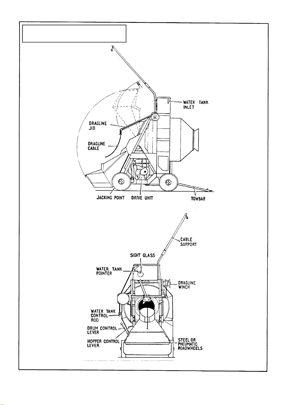
ON LATER MACHINES THE
DRAGLINE WINCH IS RELOCATED
TO THE CENTRE OF THE MAINFRAME
IN FRONT OF THE WATER TANK
AND THE DRAGLINE JIB IS NOT REQUIRED
(ON OPPOSITE SIDE
OF TANK)
ON LATER MACHINES THE
DRAGLINE WINCH IS RELOCATED
TO THE CENTRE OF THE MAINFRAME
IN FRONT OF THE WATER TANK
AND THE DRAGLINE JIB IS NOT REQUIRED
Page 36
DIMENSIONS
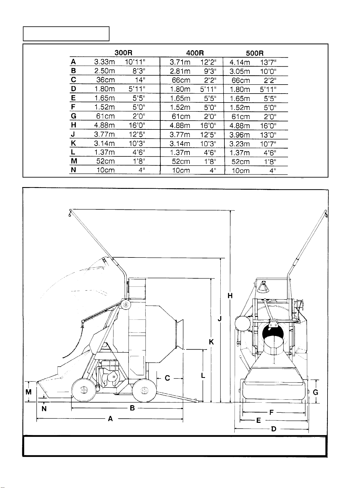
ALL STATED DIMENSIONS ARE APPROXIMATE AND CANNOT BE GUARANTEED DUE TO OUR
POLICY OF CONTINUOUS PRODUCT IMPROVEMENTS AND IMPROVEMENTS IN SPECIFICATION
Page 37

WORKSHOP MANUAL
300R & 400R
SECTION 4
SERVICE SCHEDULES
LUBRICATION DIAGRAM
Page 38

WORKSHOP MANUAL
300R 400R
WINGET REVERSING DRUM CONCRETE MIXERS
ISSUE 8 2012
Service Schedule
The engine will require additional services or adjustments in addition to
those listed below. (See the appropriate Engine Operators Handbook or
Workshop Manual)
Daily: (8) Hours
Before Work
Lubricate all grease points.
Check fuel and lubricating oil levels.
Check for oil and fuel leaks.
Check/clean/replace air filter element, cup and baffle.
After Work
Top up fuel tank.
Clean out drum and hopper
Wash down the mixer
Drain the water tank or flow meter.
Weekly: (40 Hours)
The above and the following:
Dragline Wire Rope Check for wear or damage
Drive Chain Check tension, adjust if necessary
Drive Chain Case Check oil level, top up if necessary.
Ref: SHSC1216
Page 39

WORKSHOP MANUAL
300R 400R
WINGET REVERSING DRUM CONCRETE MIXERS
ISSUE 8 2012
Hydraulic Oil Check level in main and header tanks.
(with hopper down and engine stopped)
Dynamo/Alternator Drive Check belt tension, adjust if necessary
Controls and Pivots Lubricate all levers, rods, pivots and pins with oil
Battery Check terminals, clean if necessary, top up
Monthly: (100 Hours)
The above and the following:
Hydraulic Tank Check oil tank, filler and breather, clean if
necessary.
Drum Drive Inspect and lubricate the faces and teeth of the
drum track ring, gear idler rollers and edge rollers
using open gear lubricant.
Every 3 Months: (300 Hours)
The above and the following:
Engine Change air filter element
Change lubrication oil and filter
Change fuel filter
(Also see relevant Engine Handbook/Workshop Manual)
Every 6 Months: (600 Hours)
The above and the following:
Gearbox Drain and refill
Drive Chain Case Drain and refill
Ref: SHSC1216
Page 40

WORKSHOP MANUAL
300R 400R
WINGET REVERSING DRUM CONCRETE MIXERS
ISSUE 8 2012
Every 12 Months: (1200 Hours or earlier if conditions dictate)
The above and the following:
Hydraulics Drain and clean out tank, suction strainer and
filling filter, refill with clean hydraulic oil.
Ref: SHSC1216
Page 41
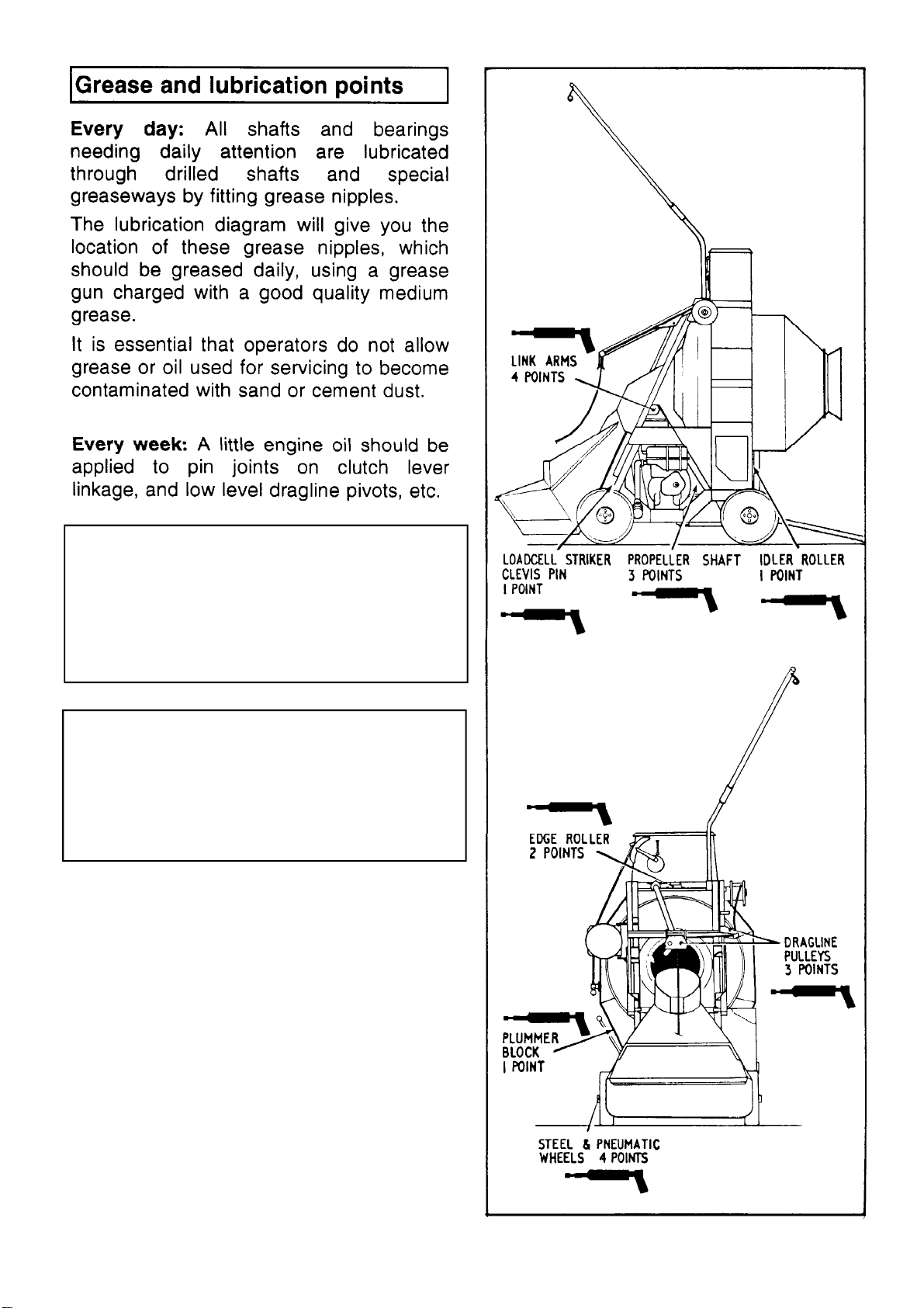
Note:- later mixers will not be fitted with all
the Lubrication & Grease points shown
as sealed for life roller bearings are used
extensively where ever possible.
Lubricate drum drive gears and drum
track and roller contact surfaces using
open gear lubricant on a regular basis, in
some operating conditions the gears and
track should be lubricated every 40 hours
or weekly.
Page 42

WORKSHOP MANUAL
300R & 400R
SECTION 5
HYDRAULIC CIRCUIT
DIAGRAMS
Page 43
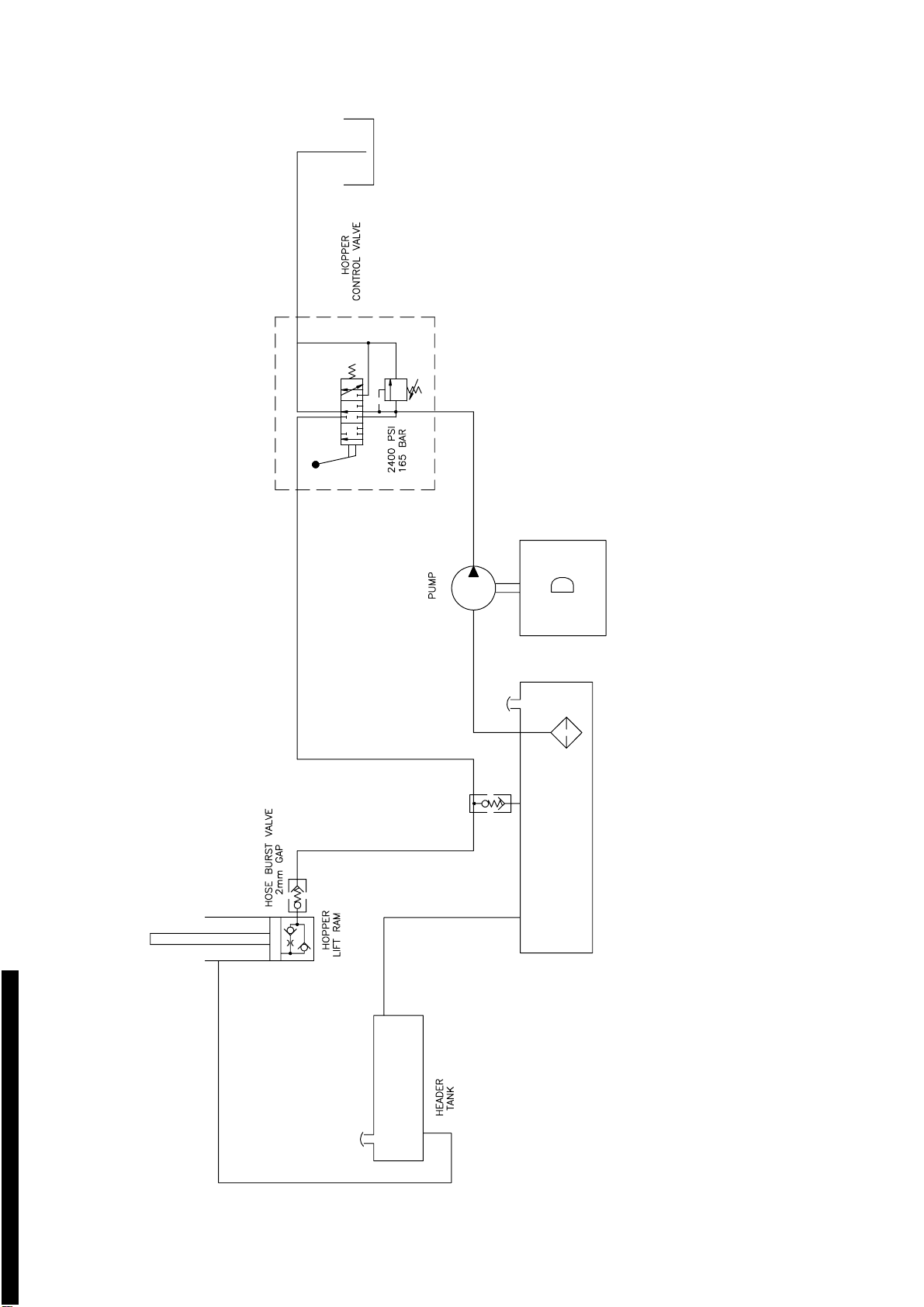
Hyd circuit.dwg 04/03/02 12:56:51 Scaled to fit
Page 44
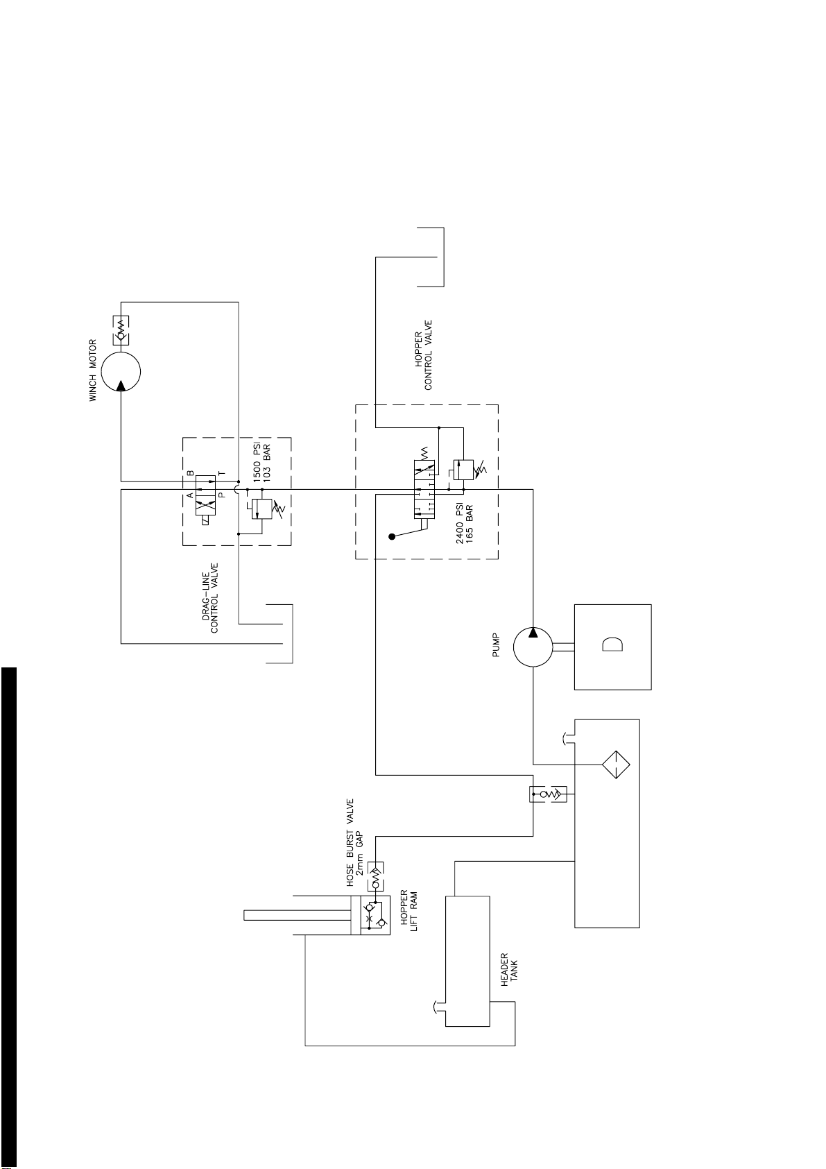
Hyd. Circuit - RSeries Mixer (With dragline).dwg 04/03/02 12:58:17 Scaled to fit
Page 45

WORKSHOP MANUAL
300R & 400R
SECTION 6
WIRING DIAGRAMS
Page 46
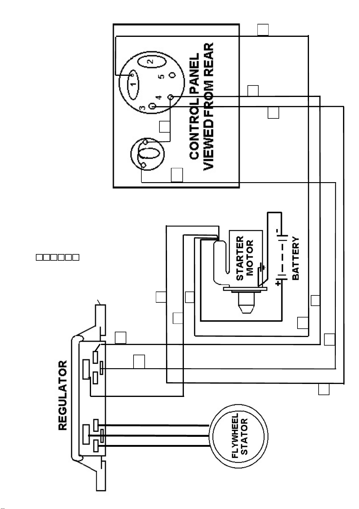
2
WIRING COLOUR CODES
(BRIDGE WIRE)
(THIN)
WHITE/RED
RED (THICK)
1 STARTER MOTOR-REG’B’
RED
BLACK
BLACK
2 START SWITCH TER 1-STARTER MOTOR BROWN
3 START SWITCH TER 3 -STARTER SOLENOID
4 START SWITCH TER 4-REG ‘C’
5 REG’LE’-WARNING LAMP
6 START SWITCH TER 4- LAMP
START SWITCH
WARNING LIGHT
6
14/0.30
5
4
3
65/0.30
35/0.30
TO AVOID BREAKING
MOUNTING LUGS OFF THE
REGULATOR CLEAN PAINT OFF THE
FANSHROUD BOSSES
4
C
LE
B+
WIRING DIAGRAM
AND ENSURE REGULATOR
IS SEATED LEVEL ON BOTH
BOSSES
5
3 35/0.30
1 35/0.30
YELLOW
RED
YELLOW
2 65/0.30
2
14/0.30
4
5
3
14/0.30
/4B2500/4B3000/4S2000E/4S2500E/200TM/300R/400R/500R/FFB COLLECTOR 1000
21000/2B1500/2B2000/4B2000
LISTER-PETTER ‘NISCA’ CHARGING SYSTEM
Page 47
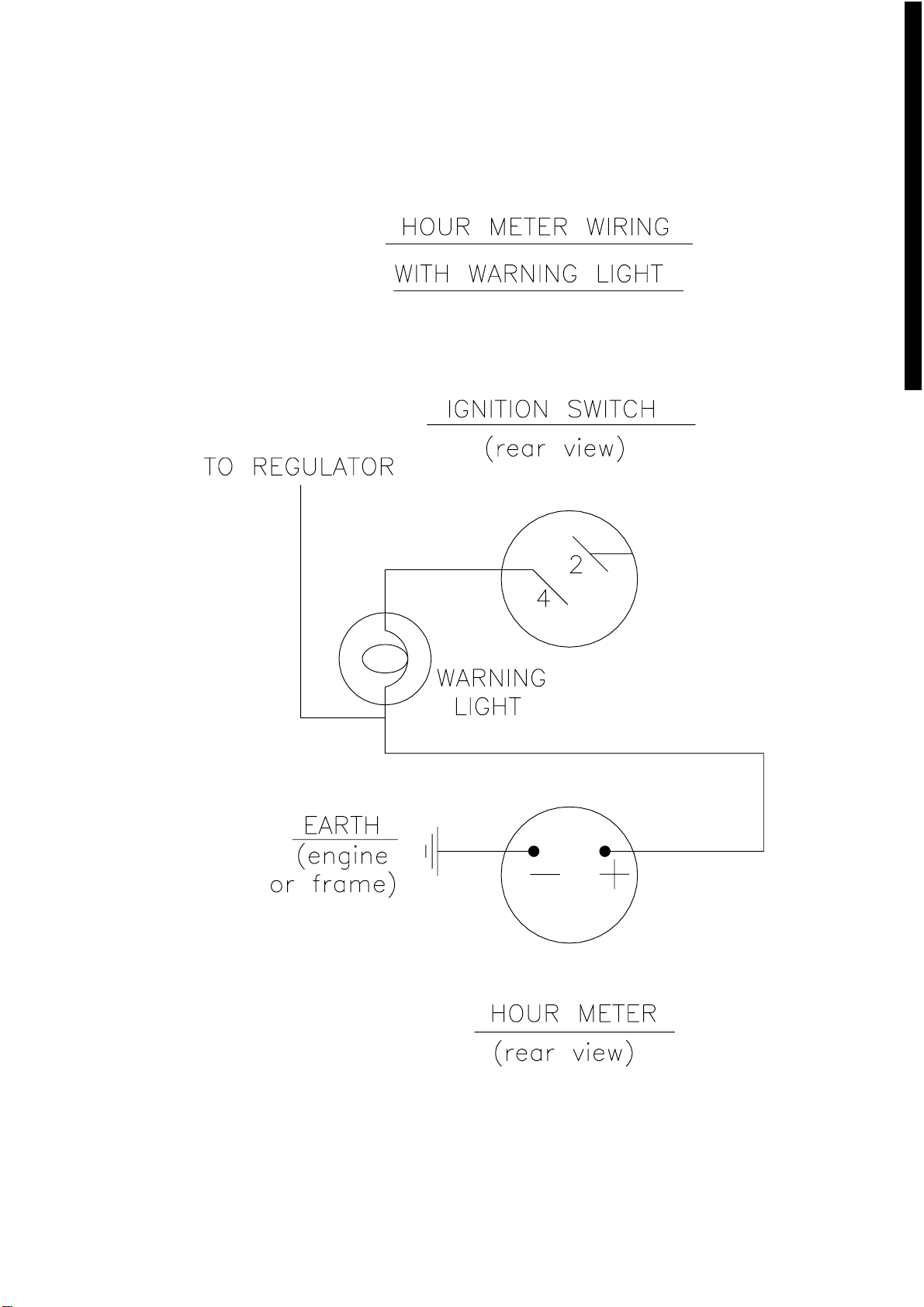
Hourmeter & lamp.dwg 04/03/02 12:50:36 Scaled to fit
Page 48
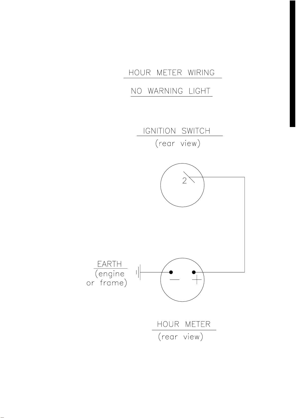
Hourmeter no lamp.dwg 04/03/02 12:53:33 Scaled to fit
Page 49
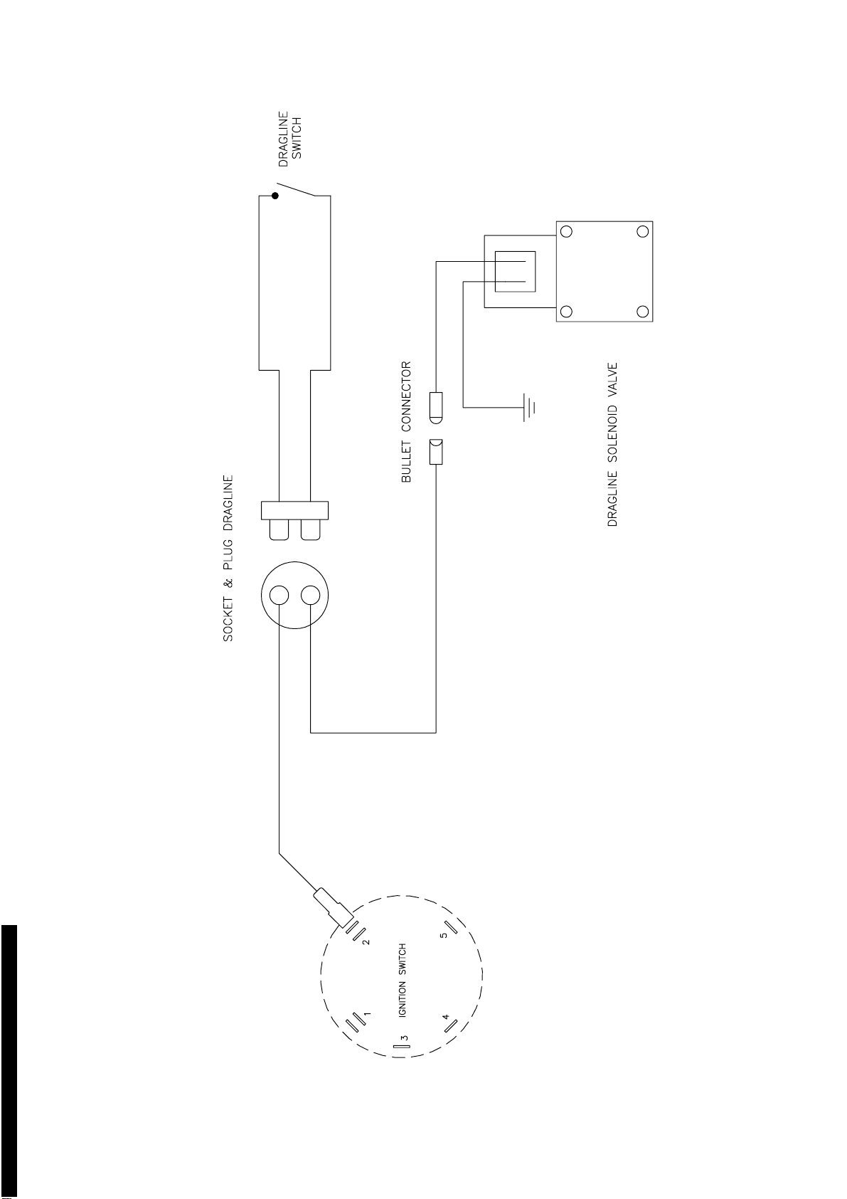
loom.dwg 04/03/02 12:59:24 Scaled to fit
Page 50
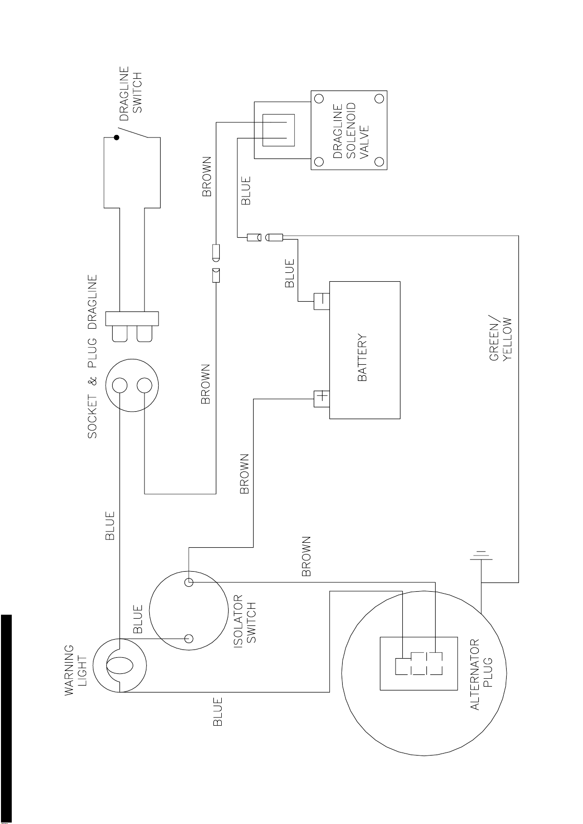
Alternator.dwg 04/03/02 13:33:44 Scaled to fit
Page 51

WORKSHOP MANUAL
300R & 400R
SECTION 7
NOISE LEVELS
Page 52

SECTION 7
NOISE LEVELS
Noise Tests were carried out in accordance with EC Directive 79/113 on a 10
metre Hemisphere with the drum empty and rotating and in accordance with EC
Directive 2000/14/EC again on a 10 metre hemisphere with the drum loaded and
rotating.
Operators Ear Tests were carried out at a distance 1 metre from the Drum and
Hydraulic Control Levers at a height of 1 metre.
Lister Petter TS2-08 Standard Build (79/113)
10 metre 111Lwa
Operators Ear 98Lpa
Lister Petter TS2-08 Standard Build (2000/14/EC)
10 metre 115Lwa
Operators Ear 98Lpa
Lister Petter TS2-63 Low Noise Build with cladding kit fitted to
mainframe and engine (79/113)
10 metre 109Lwa
Operators Ear 97Lpa
415 Volt Electric Motor (79/113)
10 metre 109Lwa
Page 53

WORKSHOP MANUAL
300R & 400R
SECTION 8
SPECIAL TOOLS
Page 54
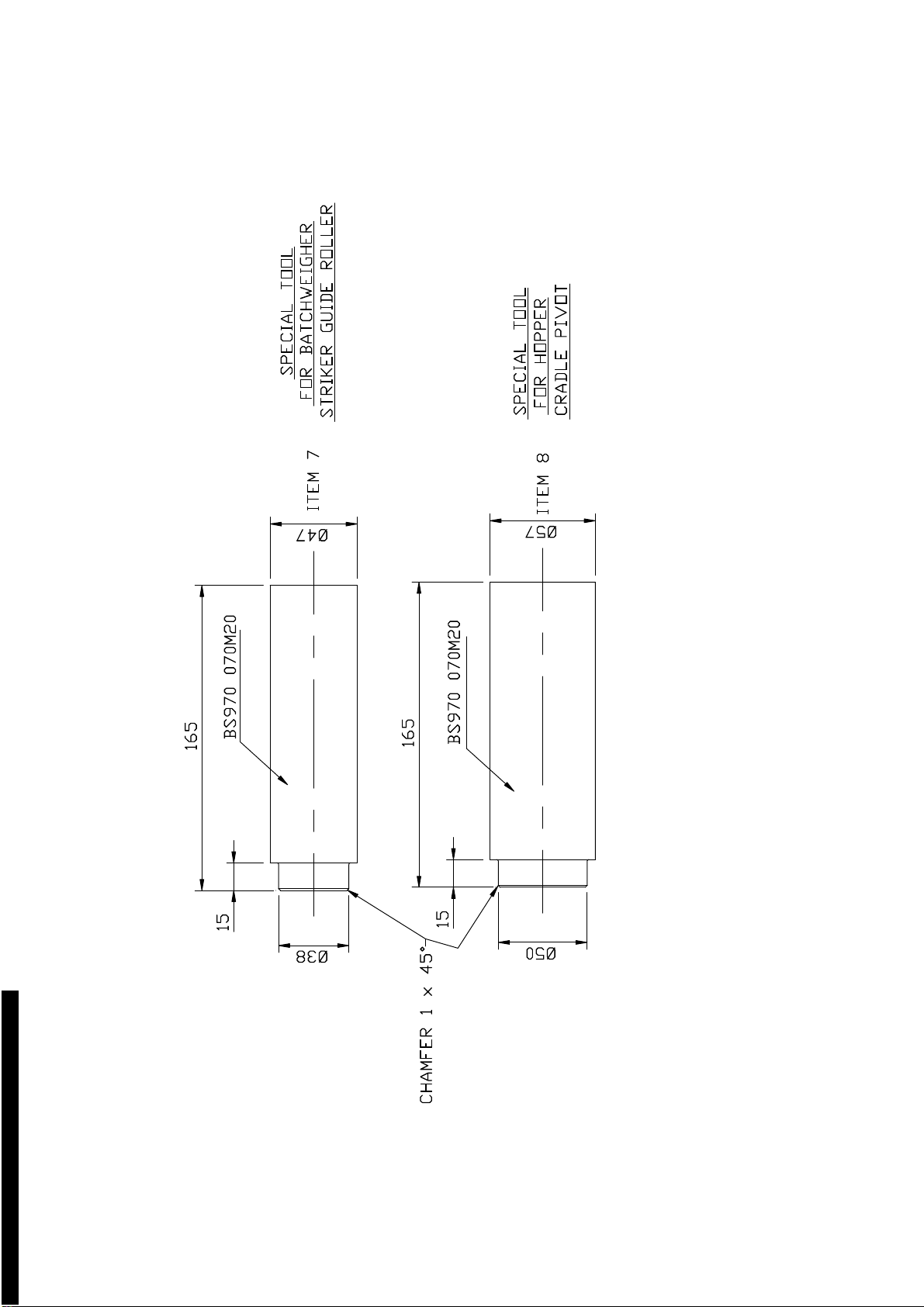
TOOL1.dwg 04/03/02 13:02:23 Scaled to fit
Page 55
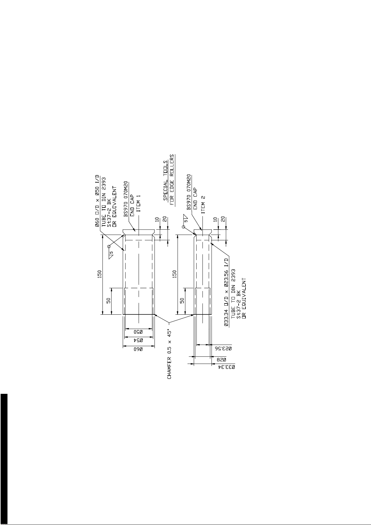
TOOLS3.dwg 04/03/02 13:06:20 Scaled to fit
Page 56
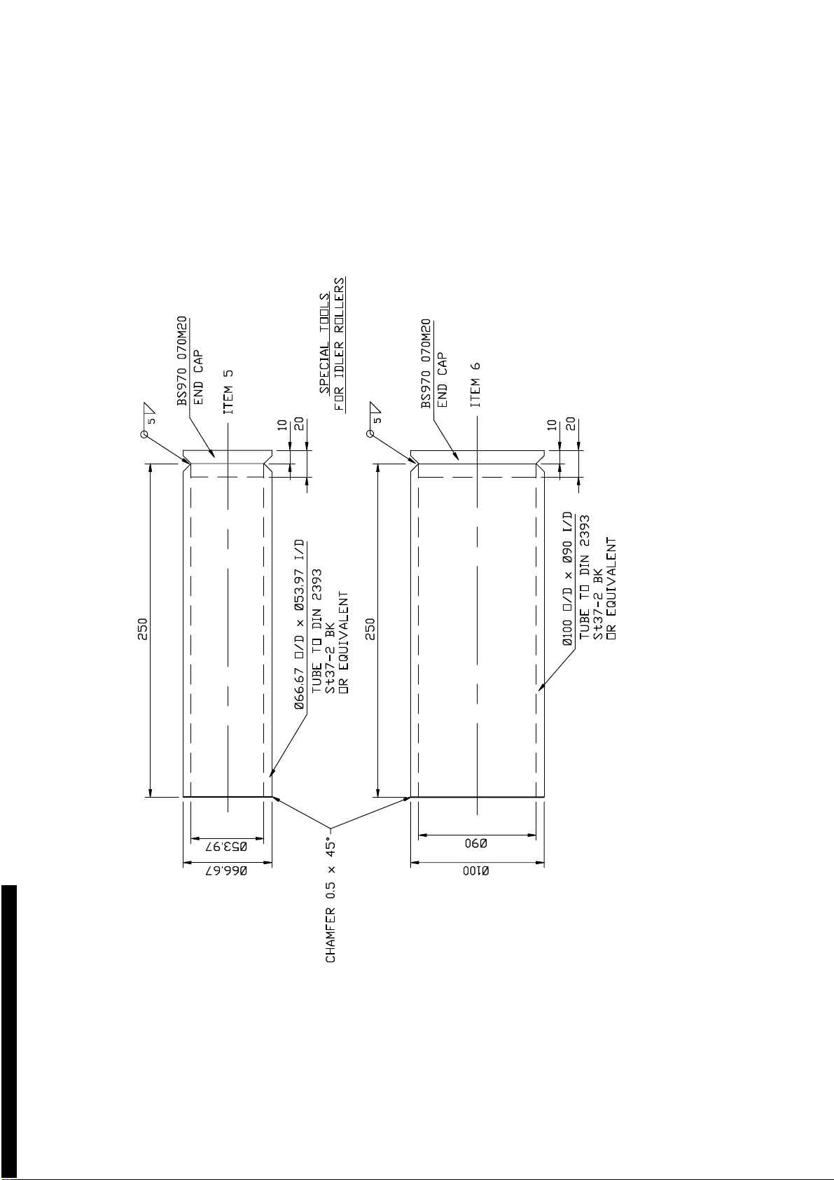
TOOLS2.dwg 04/03/02 13:07:58 Scaled to fit
Page 57
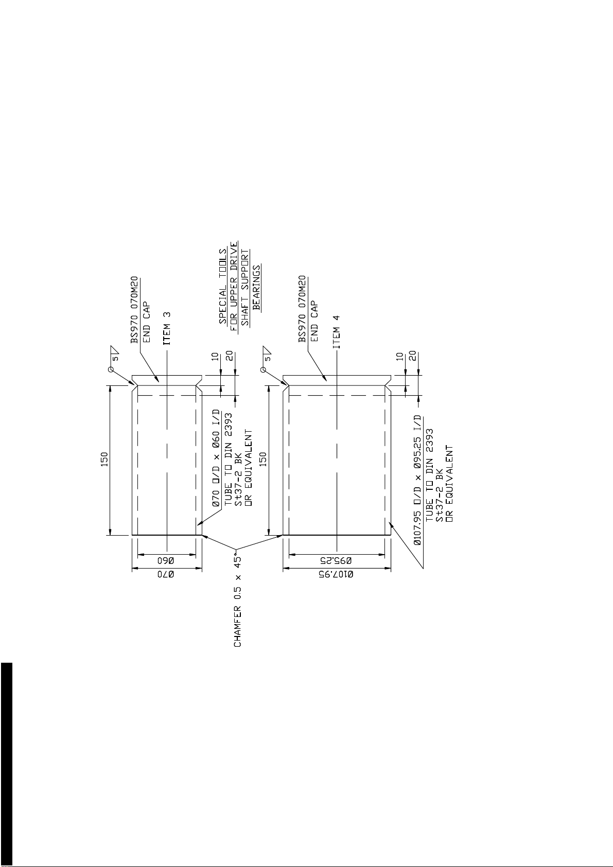
TOOL.dwg 04/03/02 13:01:18 Scaled to fit
Page 58

WORKSHOP MANUAL
300R & 400R
SECTION 9
HYDRAULIC CONTROL
VALVE SERVICE MANUAL
Page 59

PAGE INTENTIONALLY BLANK
Page 60

WORKSHOP MANUAL
300R & 400R
SECTION 10
PARTS LISTINGS
Page 61

The following Parts Illustrations do not contain a
breakdown of assemblies such as Gearbox, Drum,
Hydraulic Ram etc, only the complete items are shown.
For a breakdown of these items please refer to the
Operators and Parts Manual
Page 62
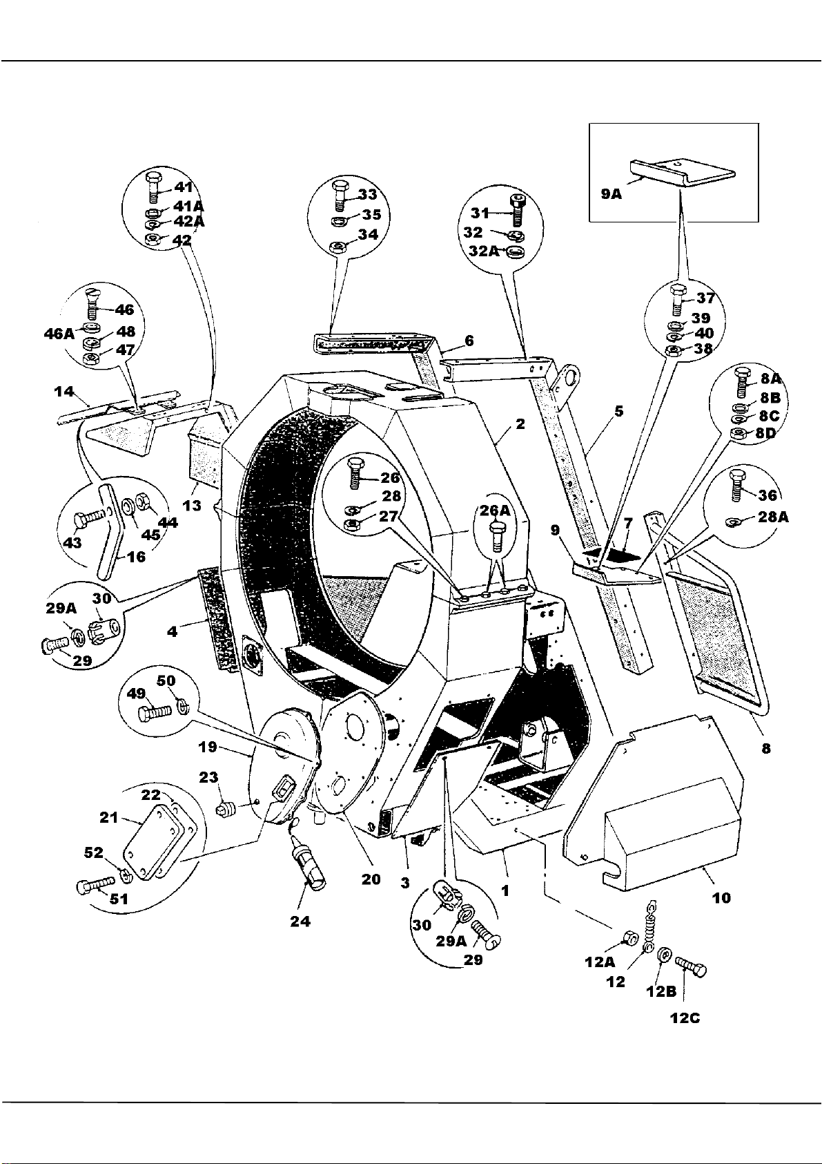
400R MAINFRAME, TANK SUPPORTS AND COVERS
FIT SPACING WASHERS V2004220 BETWEEN
FUEL TANK SHROUD, ITEM 13 AND MAINFRAME
TO AVOID DISTORTING SHROUD.
RUN SILICONE SEALER ROUND REAR FACE OF
PLATE, ITEM 20, PRIOR TO ASSEMBLY. RUN
A BEAD OF SILICONE AROUND FLANGE FACE
OF COVER, ITEM 19, ALLOW TO CURE FOR A
SHORT TIME PRIOR TO ASSEMBLY. DO NOT
FILL CHAIN CASE WITH OIL UNTIL SEALER HAS
FULLY CURED.
Page 63

400R MAINFRAME TANK SUPPORTS + COVERS
1 555272300 MAINFRAME 1
2 555130600 DRUM GUARD 1
3 555264802 GUARD PLATE LH 1
4 555264801 GUARD PLATE RH 1
5 555145700 SUPPORT WATER TANK LH 1
6 555145600 SUPPORT WATER TANK RH 1
7 V2003183 SAFETY WALK 1
8 555189900 GUARD/FENCE UK/EUROPE 1
9 555190400 STEP UK/EUROPE 1
9A 555163500 STEP - EXPORT 1
10 555131500 COVER - CONTROL SIDE 1
12 221101000 SPRING CATCH 1
12A 192S01 NUT BINX 1
12B 10S02 WASHER FLAT 1
12C 66S02A SCREW SET 1
13 555193100 SHROUD - FUEL TANK 1
14 555193200 COVER - FUEL TANK 1
16 555193400 LATCH 1
19 555263900 COVER - CHAIN CASE 1
20 555257800 PLATE - CHAIN CASE 1
21 555114700 COVER - CHAIN INSPECTION 1
22 555168100 GASKET - COVER 1
23 127S03 PLUG BLANK 3/8 BSP 1
23A 100S03 SEAL BONDED 3/8 (NOT ILLUSTRATED) 1
24 V2000772 SILICONE SEALER 1
26 28S03E SCREW SET 6
26A 6S03B BOLT (WATER TANK OPERATING ROD BRACKET) 2
27 87S03 NUT BINX 8
28 10S03 WASHER FLAT 8
28A 17S05 WASHER SPRING 4
29 16S07C SCREW SLT PAN HEAD 4
29A 17S03 WASHER SPRING 4
30 236S04 NUT BLIND NYLON 4
31 90S06H SCREW SKT CAP 6
32 41S07 WASHER SPRING 6
32A 10S04 WASHER FLAT 6
33 6S05Z SCREW SET (WATER TANK) 4
34 87S05 NUT 4
35 10S04 WASHER FLAT 4
36 11S04C SCREW SET 4
37 28S05G SCREW SET 2
38 9S04 NUT 2
39 10S04 WASHER FLAT 2
40 41S07 WASHER SPRING 2
41 28S03E SCREW SET 3
41A 10S03 WASHER FLAT 3
42 9S03 NUT 3
42A 41S05 WASHER SPRING 3
43 66S01CC SCREW SET 1
Page 64

X
400R MAINFRAME TANK SUPPORTS + COVERS
44 192S01 NUT BIN
45 10S01 WASHER FLAT 1
46 233S03F SCREW COUNTER SUNK 6
46A 267S03 WASHER FLAT 6
47 7S01 NUT 6
48 17S02 WASHER SPRING 6
49 11S03B SCREW SET 7
50 17S04 WASHER SPRING 7
51 66S01BB SCREW SET
52 41S03 WASHER SPRING 4
1
4
Page 65
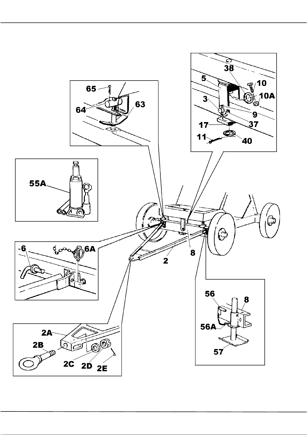
400R FRONT AXLE, TOWBARS, AXLE SPRAGS AND JACKS
COAT PINS AND WELDED BOSSES WITH
COPPERSLIP ON ASSEMBLY
COAT THREADS ON SPRAG
SCREWS ITEM 63 WITH
COPPERSLIP ON ASSEMBLY
ITEM 2B, NATO TOWING EYE SHOULD BE
CROSS DRILLED ON ASSEMBLY TO ENABLE
FITMENT OF SPLIT PIN ITEM 2E
Page 66

400R FRONT AXLE TOWBARS AXLE SPRAGS & JACKS
2 555101200 BAR TOW-STANDARD 1
2A 555283300 BAR TOW-NATO/MOD 1
2B 555283600 EYE TOWING-NATO/MOD 1
2C 150S15 WASHER FLAT 1
2D 92S15 NUT CASTLE 1
2E 44S18N PIN SPLIT 1
3 555101400 PIN PIVOT AXLE 1
5 555101900 PIVOT BRACKET 1
6 513354800 PIN RETAINING 2
6A 902S02 LYNCH PIN & CHAIN 2
8 555287300 AXLE FRONT-STANDARD/NATO 1
9 44S17K PIN SPLIT 2
10 8S03E BOLT 1
10A 61S03 NUT BINX 1
11 44S17K PIN SPLIT 2
17 555255700 TIE BAR AXLE 1
37 10S20 WASHER FLAT 2
38 10S43 WASHER FLAT 1
40 10S65 WASHER FLAT 2
55A 555285600 JACK HYDRAULIC 1
56 555267800 PIN LOCKING 4
56A 124108001 BUCKLE 4
57 555190500 SUPPORT FOOT 4
63 555256200 SCREW AXLE SPRAG 2
64 555255900 PIN AXLE SPRAG 2
65 44S05H PIN SPLIT 4
Page 67
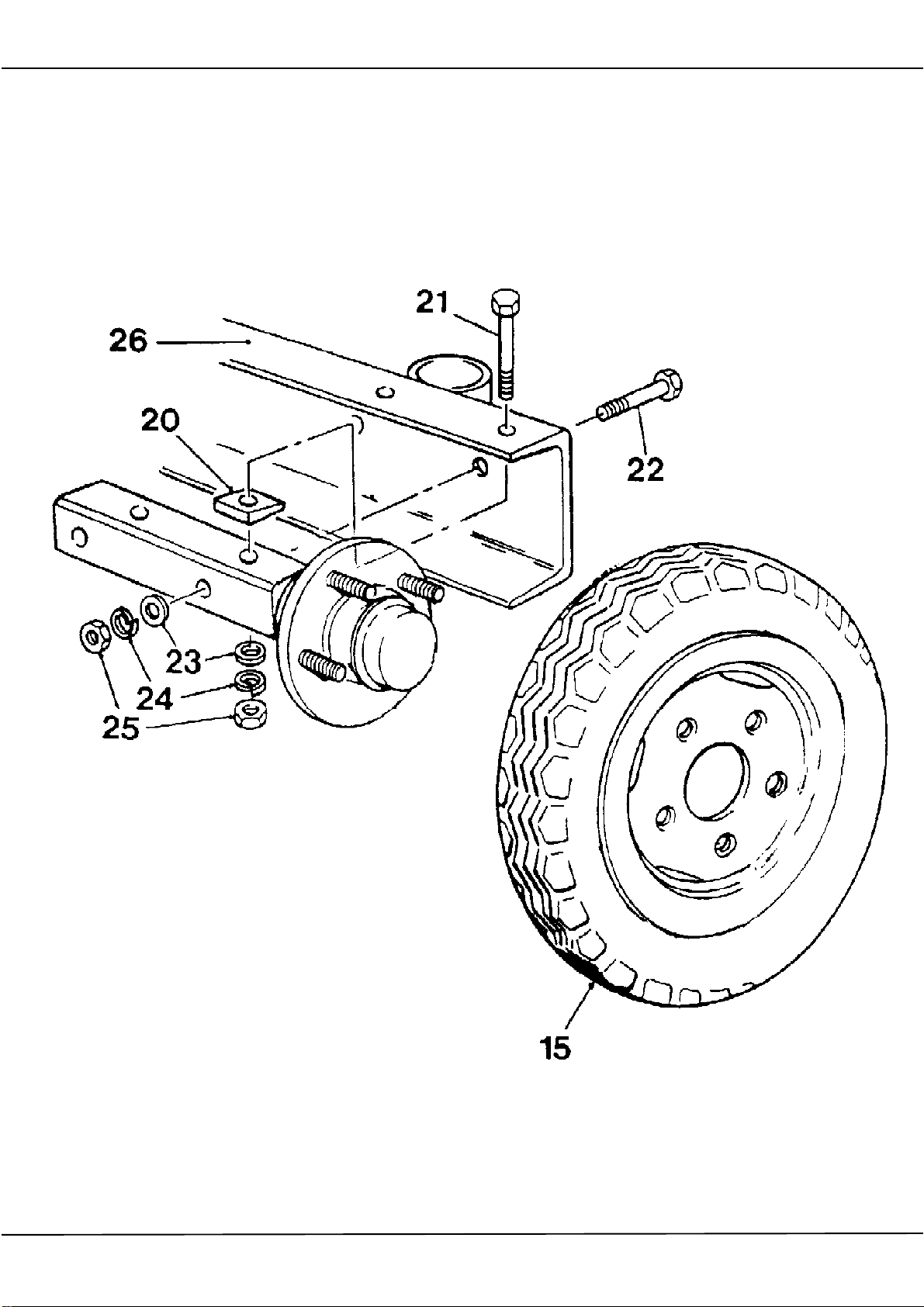
400R PNEUMATIC WHEELS, HUBS & STUB AXLES
IF THE AXLE CHANNEL SECTION IS PRODUCED
FROM PARALLEL RATHER THAN TAPERED
SECTION, SUBSTITUTE THE TAPERED
WASHERS ITEM 20 FOR FLAT WASHERS 267S07
IF BOLT ITEM 22 FOULS JACK LEG
SUPPORT BRACKET INSERT FROM
OPPOSITE SIDE
WHEN THE WHEEL IS ATTACHED TO THE HUB
ROCK THE WHEEL TO CHECK FOR EXCESS HUB
BEARING PLAY
Page 68

400R HUB STUB AXLE AND PNEUMATIC WHEELS
1 555287600 HUB & STUB AXLE ASSEMBLY (FAD) 4
15 475600019 WHEEL ASSEMBLY 4
20 105S05 WASHER TAPERED 8
21 8S05M BOLT UPPER 8
22 8S05K BOLT LOWER 8
23 267S07 WASHER FLAT 16
24 17S06 WASHER SPRING 16
25 7S05 NUT PLAIN 16
26 555226500 MAINFRAME 1
26A 555287300 AXLE FRONT-STANDARD/MOD/NATO 1
Page 69
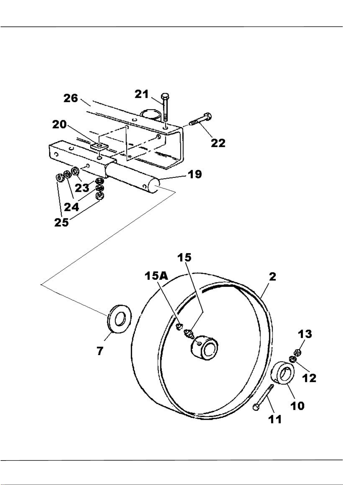
400R STEEL WHEELS AND STUB AXLE
IF THE AXLE CHANNEL SECTION IS PRODUCED
FROM PARALLEL RATHER THAN TAPERED
SECTION SUBSTITUTE THE TAPERED WASHERS
ITEM 20 FOR FLAT WASHERS 267S07
IF BOLT ITEM 22 FOULS
JACK LEG SUPPORT BRACKET
INSERT FROM OPPOSITE SIDE
COAT SHAFT WITH COPPERSLIP ON
ASSEMBLY
Page 70

400R HUB STUB AXLE AND STEEL WHEELS
2 511146701 WHEEL STEEL, FABRICATED 4
7 150S15 WASHER FLAT 4
10 555277900 COLLAR 4
11 6S03M BOLT 4
12 41S05 WASHER SPRING 4
13 9S03 NUT 4
15 131S01 NIPPLE GREASE 4
15A 176S01 CAP NIPPLE 4
19 555288500 AXLE STUB 4
20 105S05 WASHER TAPERED (SEE NOTE RE 267S07) 8
21 8S05M BOLT 8
22 8S05K BOLT 8
23 267S07 WASHER FLAT 16
24 17S06 WASHER SPRING 16
25 7S05 NUT 16
26 CHASSIS-FRONT AXLE 1
Page 71
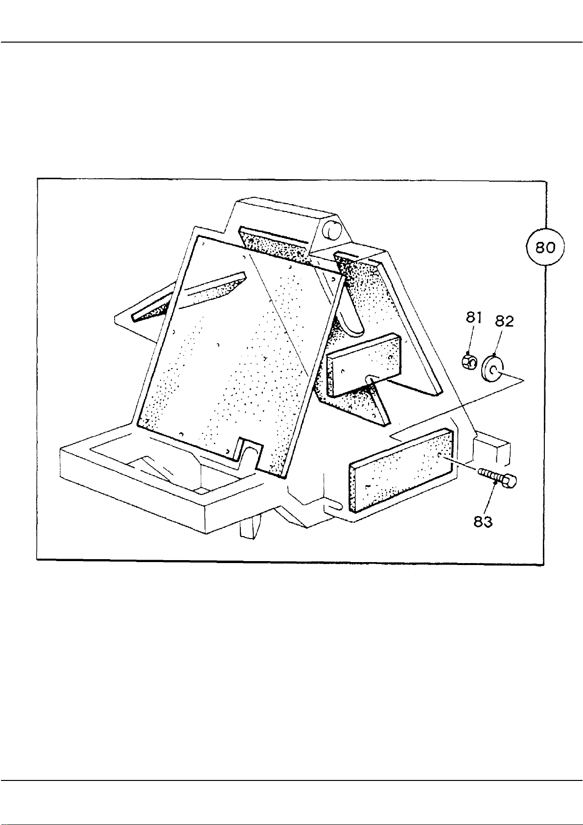
400R NOISE REDUCTION KIT
REFER TO THE ENGINEERING DRAWING WHEN
DRILLING THE MAINFRAME AND PANELS TO
SECURE THE CLADDING KIT.
Page 72

400R NOISE REDUCTION KIT
80 555286500 KIT NOISE REDUCTION 1
81 61S02 NUT BINX 30
82 10S56 WASHER 30
83 11S02C SCREW SET 30
Page 73
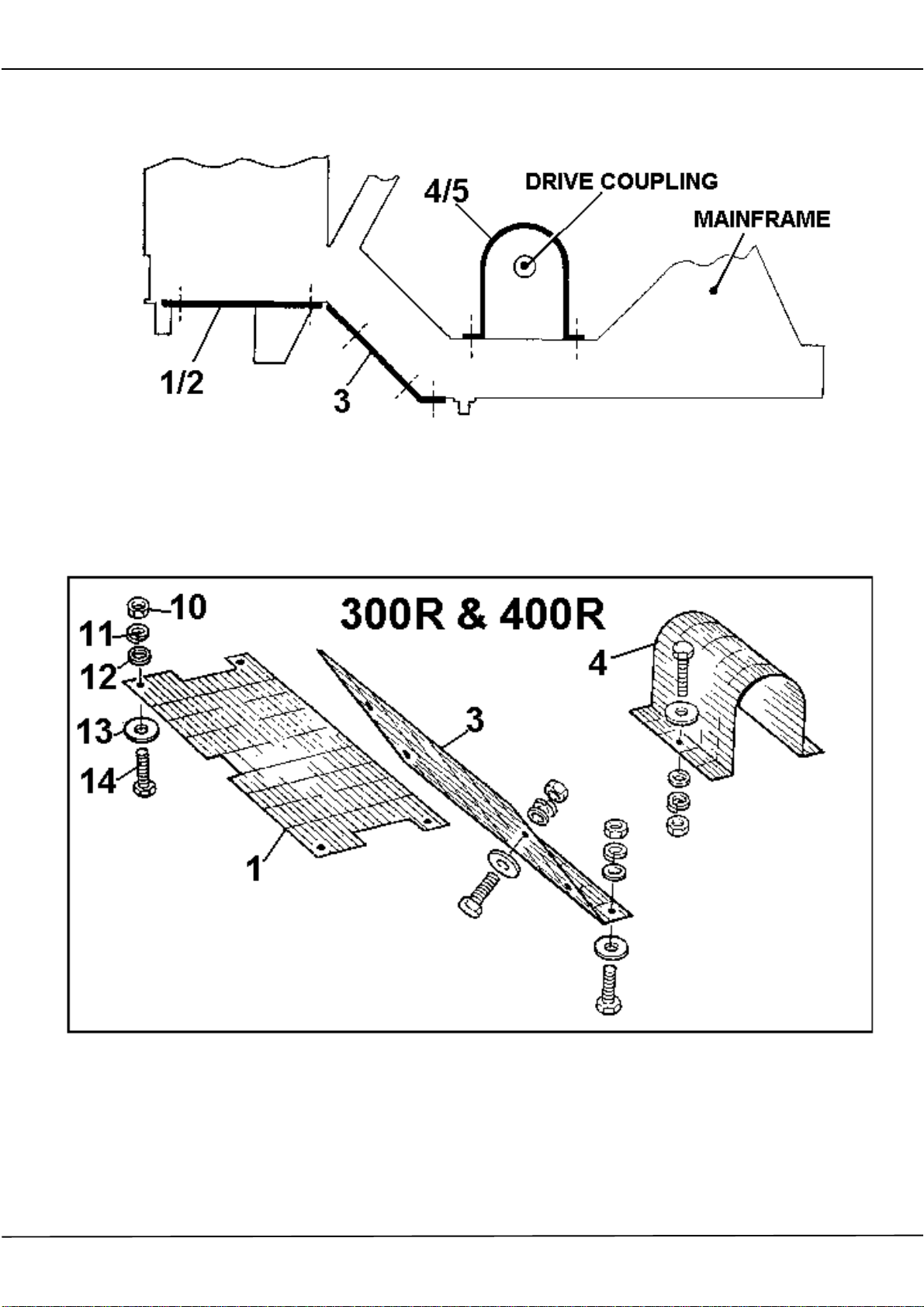
400R 'CE' GU ARDING
Page 74

400R 'CE' GUARDING
1 555290700 GUARD HORIZONTAL 1
3 555290800 GUARD ANGLED 1
4 555290900 GUARD ELECTRIC MOTOR-GEARBOX COUPLING 1
4 555291000 GUARD LISTER TS2-GEARBOX COUPLING 1
10 7S03 NUT 12
11 17S04 WASHER SPRING 12
12 267S05 WASHER FLAT 12
13 V2004220 WASHER SPECIAL 12
14 11S03C SCREW SET 12
555131500 COVER RETAINED BY:11S03C SCREW SET 2
267S05 WASHER FLAT 2
17S04 WASHER SPRING 2
7S03 NUT 2
Page 75
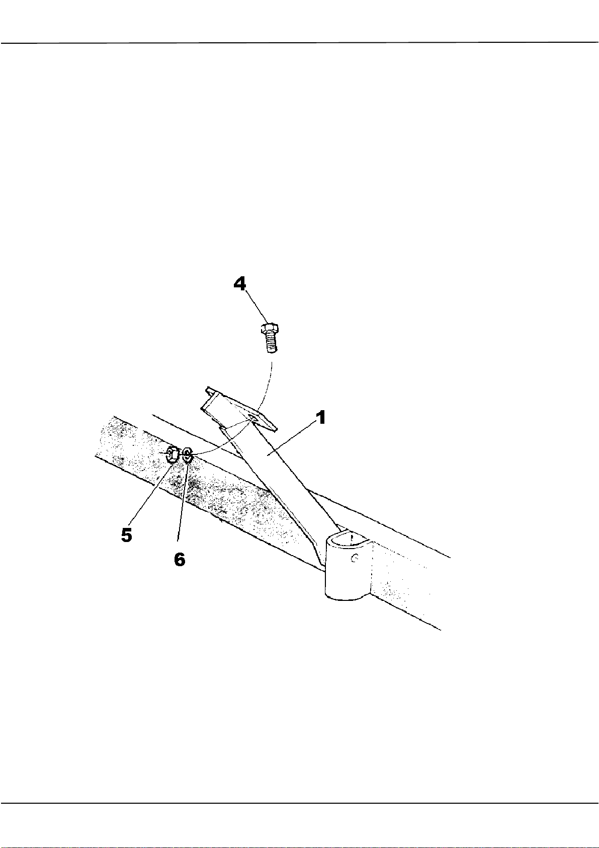
400R HOPPER ANTI BOUNCE BRACKET
ATTACH ANTI BOUNCE BRACKET BETWEEN
THE LEFT HAND SIDE OF THE HOPPER CRADLE
AND MAINFRAME TO PREVENT DAMAGE TO
COMPONENTS WHEN TRANSPORTING THE
MACHINE
Page 76

400R ANTI BOUNCE BRACKET
1 555288600 BRACKET ANTI BOUNCE 1
4 66S06D SCREW SET 1
5 104S06 NUT 1
6 41S09 WASHER SPRING 1
Page 77
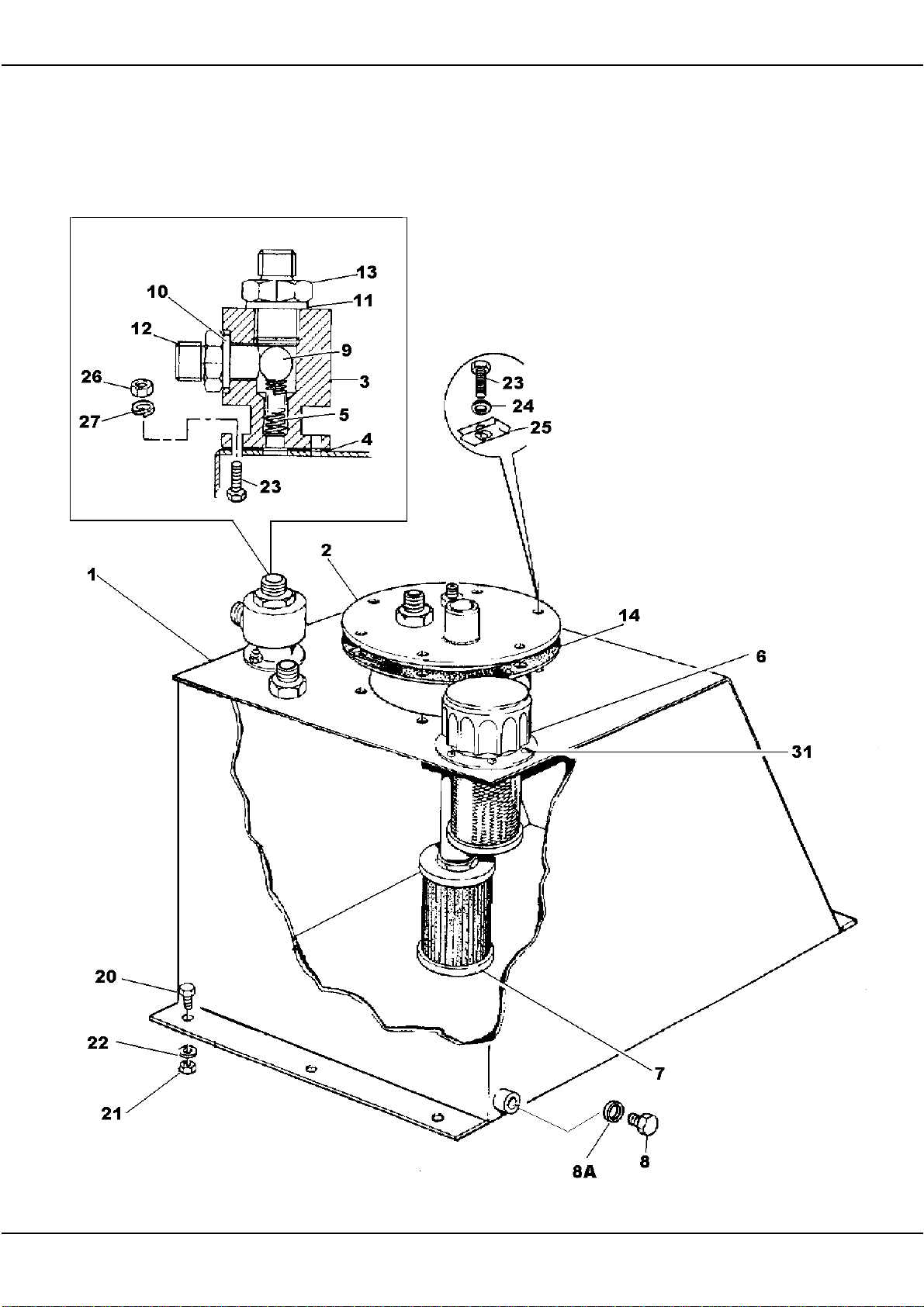
400R HYDRAULIC TANK ASSEMBLY
THE BALL ITEM 9 SHOULD BE CORRECTLY
SEATED WITHIN THE BLEED VALVE BODY
ON ASSEMBLY, PLACE THE BALL INTO THE
BODY WITHOUT THE SPRING THEN DRIVE THE
BALL DOWN ONTO ITS SEAT USING A SOFT
FACED PUNCH OR DRIFT. REMOVE THE BALL
AND DROP THE SPRING INTO PLACE,
ASSEMBLE THE VALVE AS ILLUSTRATED.
IF NO DRAGLINE IS FITTED THE
1/2 BSP THREADED PORT ON THE
TANK COVER SHOULD BE
BLANKED OFF USING A 120S03
CAP, THE HOPPER RAM RETURN
HOSE FROM THE HEADER TANK
TERMINATES AT THE1/4 BSP
PORT.
Page 78

400R HYDRAULIC TANK ASSEMBLY
1 555257900 TANK HYDRAULIC 1
2 555284800 COVER 1
3 555255600 BODY BLEED VALVE 1
4 555264000 GASKET BLEED VALVE 1
5 555267100 SPRING BLEED VALVE 1
6 10565A01 BREATHER FILLER 1
7 220591000 STRAINER 1
8 127S02 PLUG TANK DRAIN 1
8A 100S02 SEAL BONDED 1
9 101120000 BALL STEEL 1
10 100S03 SEAL BONDED 1
11 100S04 SEAL BONDED 1
12 122S03 FITTING ADAPTOR, MALE, STUD 1
13 119S08 FITTING ADAPTOR, MALE, STUD 1
14 417735000 GASKET TANK COVER 1
20 11S04C SCREW SET 3
21 7S04 NUT 3
22 17S05 WASHER FLAT 3
23 11S02A SCREW SET 8
24 17S03 WASHER SPRING 6
25 332719000 NUT CAPTIVE 6
26 7S02 NUT 2
27 17S03 WASHER SPRING 2
31 101S07E RIVET 6
Page 79
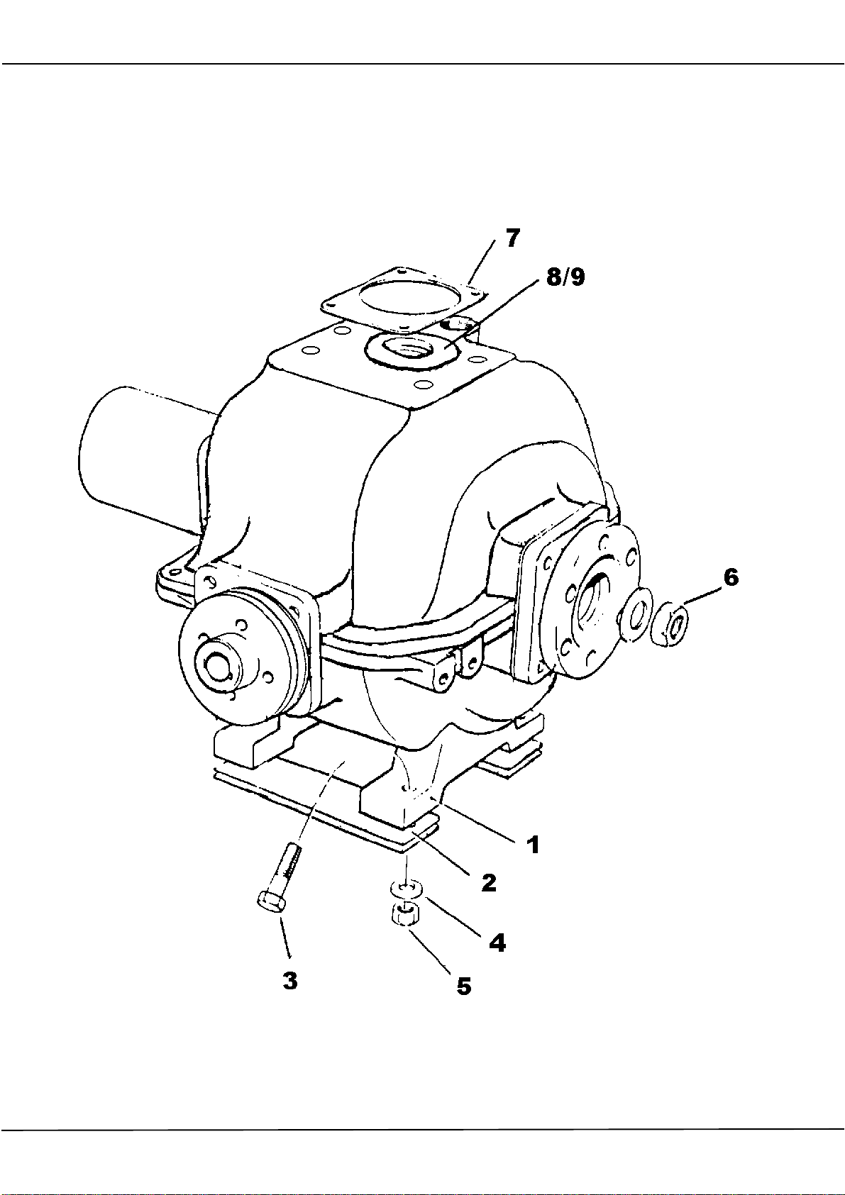
400R REVERSING GEARBOX AND FITTINGS
TO SET BACKLASH BETWEEN HYDRAULIC
PUMP AND GEARBOX BEVEL GEARS,
ASSEMBLE LOCATING RING AND GEAR ON
PUMP AND OFFER PUMP UPTO GEARBOX
WITHOUT SHIMS, MEASURE GAP BETWEEN
PUMP AND CASTING AND ADD 5-8 THOU
(0.02-0.20MM) TO MEASUREMENT OBTAINED
TO GIVE CORRECT GEAR BACKLASH. ADD SHIM
PACK EQUIVALENT TO TOTAL MEASUREMENT.
FILL WITH 20W/30 OIL
CENTRE LINE OF ENGINE AND GEARBOX
SHOULD BE ADJUSTED USING SHIM PACK ITEM
2, PLAIN NUTS ON DRIVE COUPLINGS SHOULD
BE CHANGED TO BINX NUTS.
IF DRAGLINE IS TO BE
FITTED LOOP V BELT
OVER PULLEY WHEN
FITTING GEARBOX
Page 80

400R REVERSING GEARBOX AND FITTINGS
1 555268100 GEARBOX REVERSING 1
2 555107400 SHIM PACKER SET 1
CONSISTS OF
1 X 555107401
1 X 555107402
2 X 555107403
3 6S05F BOLT 4
4 10S04 WASHER FLAT 4
5 87S05 NUT BINX 4
6 192S07 NUT BINX 2
7 SHIM SET - SUPPLIED WITH GEARBOX 1
8 555106100 GEAR PINION SUPPLIED WITH GEARBOX 1
9 555107000 WASHER CENTRE SUPPLIED WITH GEARBOX 1
Page 81
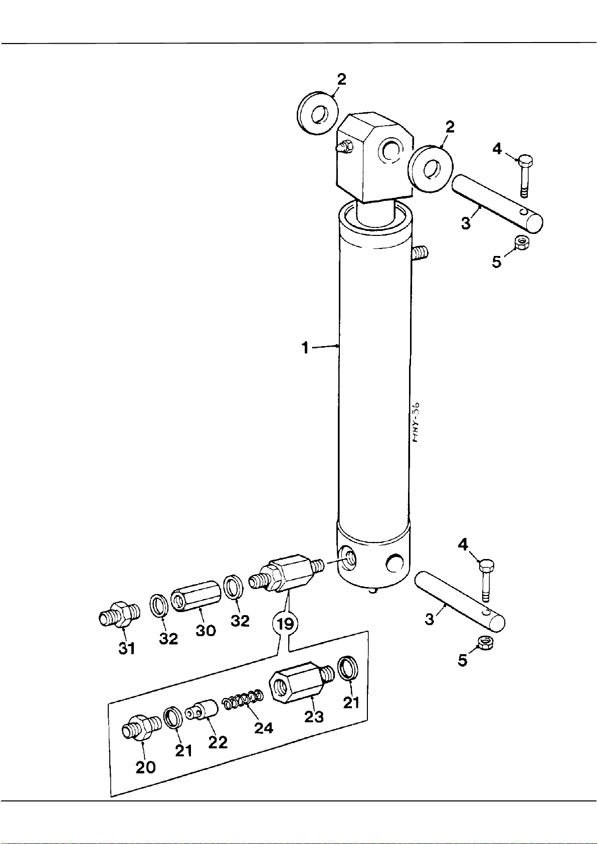
400R HOPPER RAM, RESTRICTOR & HOSE FAILURE VALVE
THE CENTRE BAFFLE ASSEMBLY
OF THE HOSE FAILURE VALVE
ITEM 30 PART NO V2004171
SHOULD BE UNSCREWED FROM
THE BODY BEFORE INSTALLATION
AND THE GAP BETWEEN THE
BAFFLES ADJUSTED TO 2.0MM,
THE BAFFLE ASSEMBLY SHOULD
THEN BE SCREWED FULLY HOME
INTO THE BODY. IT IS IMPORTANT
THAT THE VALVE IS FITTED ONTO
THE RAM THE CORRECT WAY
ROUND OTHERWISE THE VALVE
WILL FAIL TO FUNCTION CORRECTLY
THE RESTRICTOR IS FITTED TO ALL ‘CE’
MARKED AND NON ‘CE’ MARKED MACHINES,
THE HOSE FAILURE VALVE IS FITTED ONLY
TO ‘CE’ MARKED MACHINES INTENDED FOR
SALE AND USE WITHIN THE EUROPEAN
COMMUNITY.
Page 82

400R HOPPER RAM, RESTRICTOR & HOSE FAILURE VALVE
1 272150000 RAM, HOPPER 1
2 555167900 WASHER 2
3 555108500 PIN 2
4 6S03G BOLT 2
5 87S03 NUT, "BINX", SELF LOCKING 2
20 119S08 FITTING, ADAPTOR, MALE/MALE 1
21 100S04 SEAL BONDED 2
22 555247000 POPPET 1
23 555247100 FITTING, ADAPTOR, RESTRICTOR 1
24 424210500 SPRING COMPRESSION 1
30 V2004171 VALVE HOSE FAILURE 1
31 122S03 ADAPTOR MALE/MALE 1
32 100S03 SEAL BONDED 2
Page 83
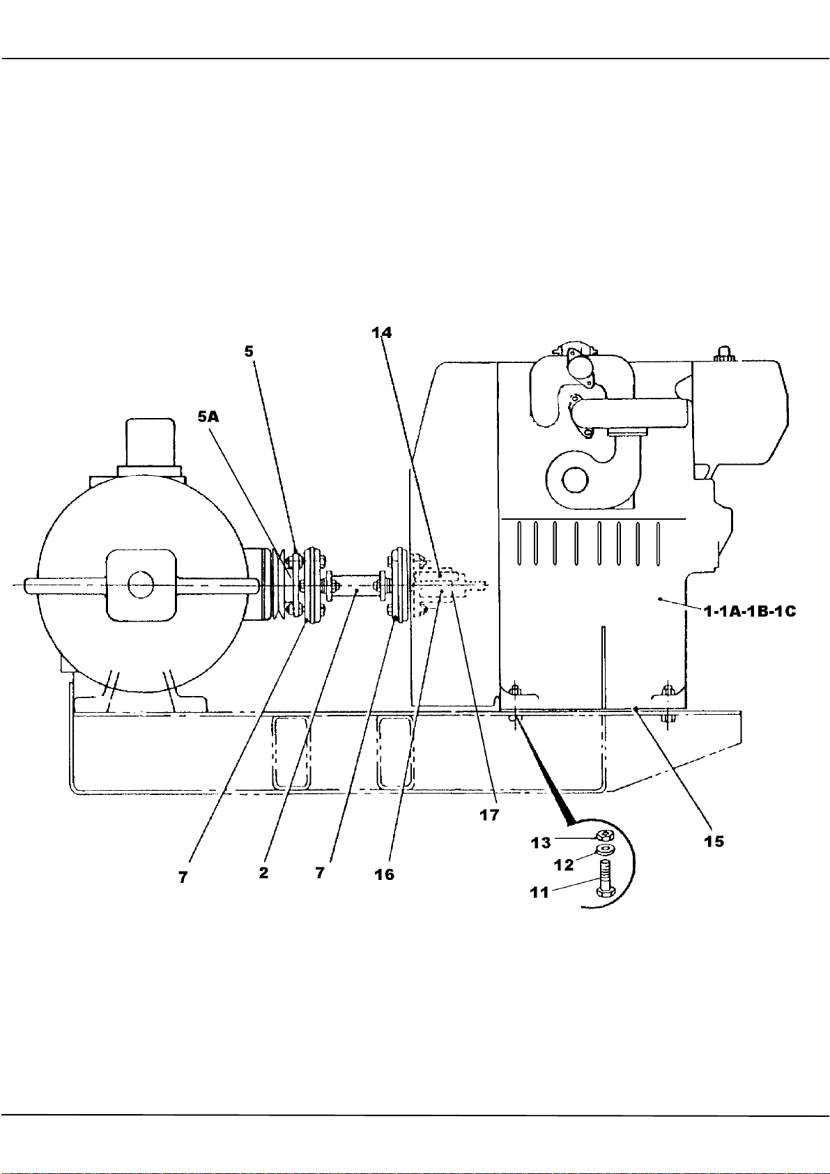
400R LISTER TR2 ENGINE AND COUPLING
SET ENGINE RPM TO 1800
UK ENGINES MUST BE FILLED WITH 10W/30
ENGINE OIL.
CENTRES OF ENGINE AND GEARBOX
OUTPUT/INPUT SHAFTS MUST BE ALIGNED
TO AVOID STRAINING SHAFT AND LAYRUB
COUPLINGS.
Page 84

400R ENGINE & COUPLING LISTER TR2
1 20350A03 ENGINE LISTER TR2 HANDSTART (EXPORT VERSION) 1
1A 20350A06 ENGINE LISTER TR2 ELECTRIC START (EXPORT VERSION) 1
1B 20350A07 ENGINE LISTER TR2 HAND START (UK/EEC VERSION) 1
1C 20350A08 ENGINE LISTER TR2 ELECTRIC START (UK/EEC VERSION) 1
2 555280400 SHAFT CONNECTING 1
5 555258100 ADAPTOR DRIVESHAFT 1
5A 90S04H SCREW SOCKET CAP (NOT ILLUSTRATED) 4
7 130972000 COUPLING LAYRUB 2
11 6S05K BOLT ENGINE 4
12 10S04 WASHER FLAT 4
13 87S05 NUT BINX "SELF LOCKING" 4
14 304712863 KEY PARALLEL 1
15 555280300 PACKER ENGINE 2
16 555280500 FLANGED DRIVE SHAFT 1
17 195S03C2 SCREW GRUB- FLANGED DRIVE SHAFT 1
COUPLING FIXINGS
THE NUTS BOLTS AND WASHERS (61S05, 8S05H, 267S07) ARE SUPPLIED WITH THE
LAYRUB COUPLINGS ITEM 7 130972000
Page 85
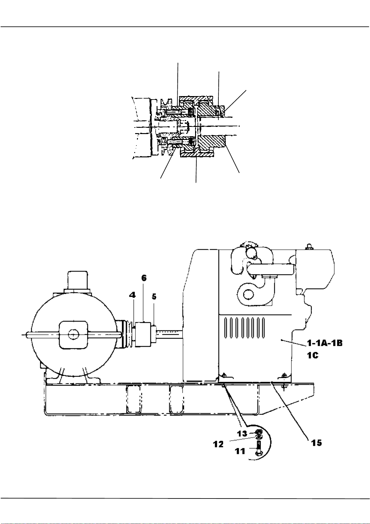
400R LISTER TR2 ENGINE AND COUPLING APRIL 2010 ON
SET ENGINE RPM TO 1800
8
UK ENGINES MUST BE FILLED
WITH 10W/30 ENGINE OIL.
9
7
4 5
6
CENTRES OF ENGINE AND GEARBOX OUTPUT/
INPUT SHAFTS MUST BE ALIGNED TO AVOID
STRAINING COUPLING AND SLEEVE
Page 86

400R ENGINE & COUPLING LISTER TR2 APRIL 2010 ON
1 20350A03 ENGINE LISTER TR2 HANDSTART (EXPORT VERSION) 1
1A 20350A06 ENGINE LISTER TR2 ELECTRIC START (EXPORT VERSION) 1
1B 20350A07 ENGINE LISTER TR2 HAND START (UK/EEC VERSION) 1
1C 20350A08 ENGINE LISTER TR2 ELECTRIC START (UK/EEC VERSION) 1
LONG EXTENSION SHAFT FITTED TO ENGINE
4 555248601 COUPLING-GEARBOX 1
5 555280900 COUPLING-ENGINE 1
6 147320001 SLEEVE COUPLING-NYLON 1
7 304712863 KEY PARALLEL 1
8 90S04L SCREW SOCKET CAP 4
9 188S04E1 SCREW GRUB 1
11 6S05K BOLT ENGINE 4
12 10S04 WASHER FLAT 4
13 87S05 NUT BINX "SELF LOCKING" 4
15 555280300 SHIM PACKER ENGINE 2
1
Page 87
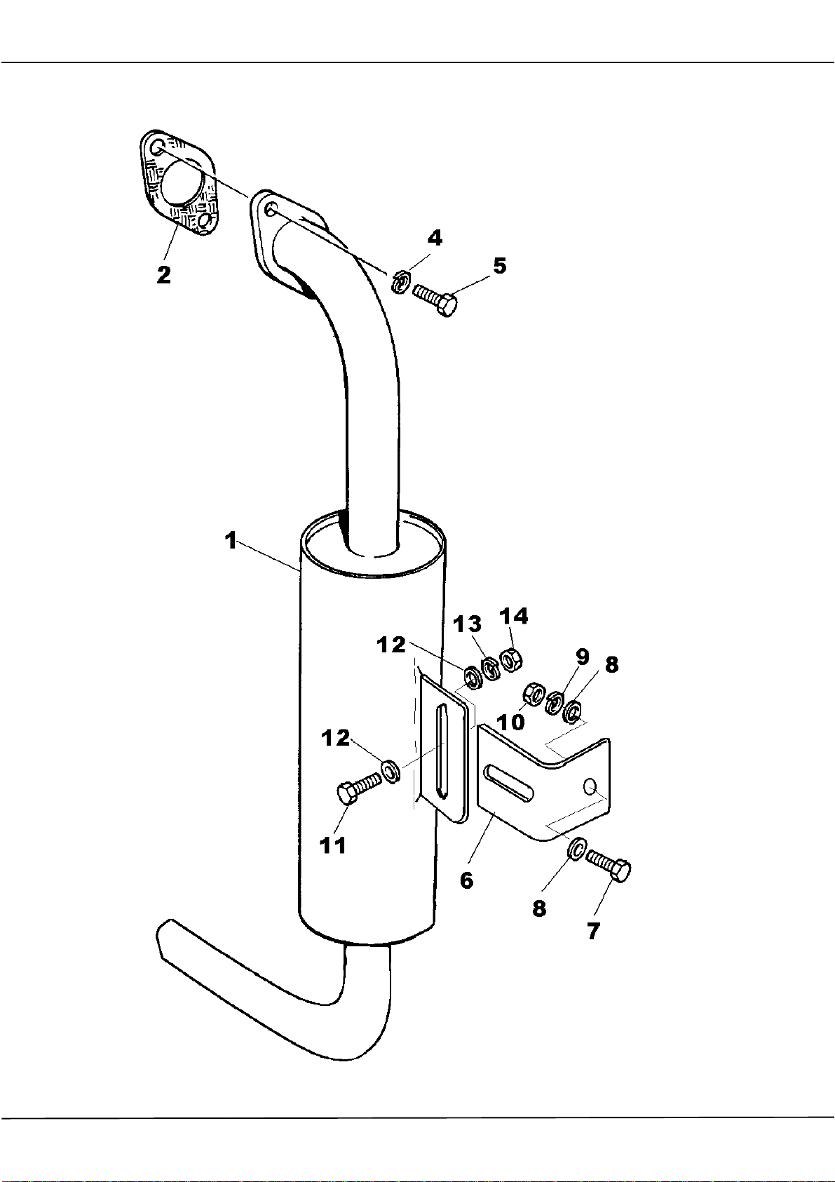
400R EXHAUST SILENCER
SETSCREW ITEM 7 PICKS UP ON MAINFRAME
Page 88

400R EXHAUST SILENCER
1 555288900 SILENCER ACOUSTIC EXHAUST 1
2 10293A03 GASKET 1
4 17S05 WASHER SPRING M10 2
5 11S04C SCREW SET M10 2
6 555289000 BRACKET SILENCER SUPPORT 1
7 11S04F SCREW SET M10 1
8 267S06 WASHER FLAT M10 2
9 17S05 WASHER SPRING M10 1
10 7S04 NUT M10 1
11 11S04C SCREW SET M10 1
12 267S06 WASHER FLAT M10 2
13 17S05 WASHER SPRING M10 1
14 7S04 NUT M10 1
Page 89
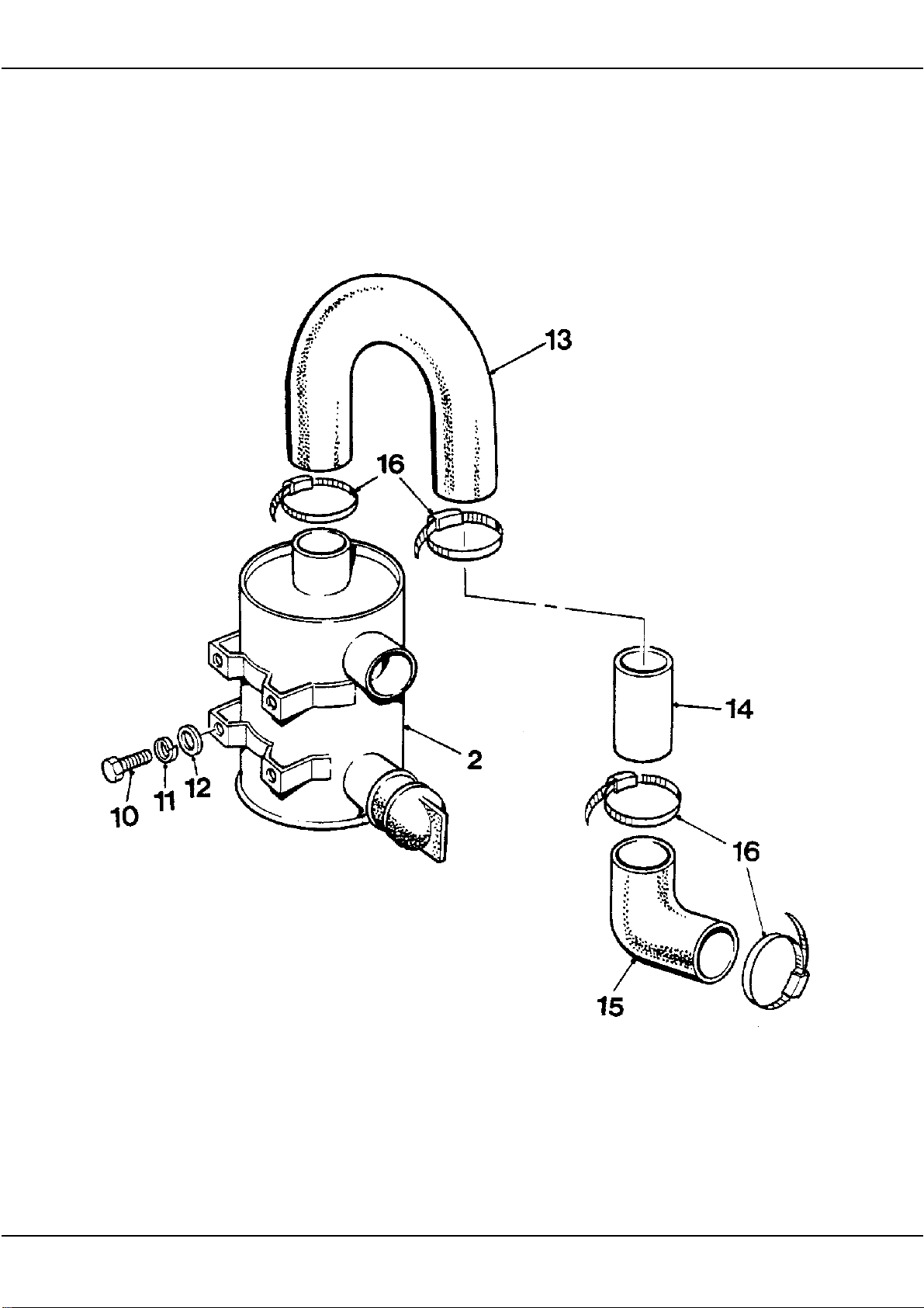
400R AIR CLEANER AND PIPEWORK- FILTREL
Page 90

400R AIR FILTER AND PIPEWORK-FILTREL
1 V2004797 AIR FILTER ASSEMBLY, FILTREL 1
10 11S03B SCREW SET 4
11 17S04 WASHER SPRING 4
12 267S05 WASHER FLAT 4
13 555188700 HOSE ELBOW RUBBER INLET 1
14 555280000 TUBE INLET STEEL 1
15 V600187 HOSE ELBOW 90' RUBBER 1
16 97S13 CLIP HOSE 4
Page 91
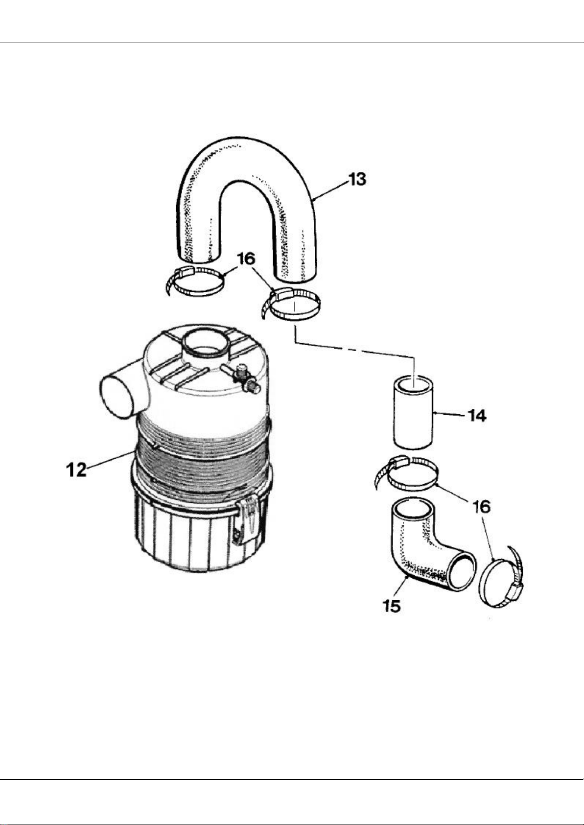
400R AIR CLEANER AND PIPEWORK- VIRGIO
Page 92

400R AIR FILTER AND PIPEWORK-VIRGIO
12 V2005807 AIR FILTER ASSEMBLY C/W BAND, VIRGIO 1
12A 11S03D SCREW SET, M8 X 30, 2
12B 267S05 WASHER FLAT 4
12C 61S03 NUT BINX 2
13 555188700 HOSE ELBOW RUBBER INLET 1
14 555280000 TUBE INLET STEEL 1
15 V600187 HOSE ELBOW 90' RUBBER 1
16 97S13 CLIP HOSE 4
Page 93
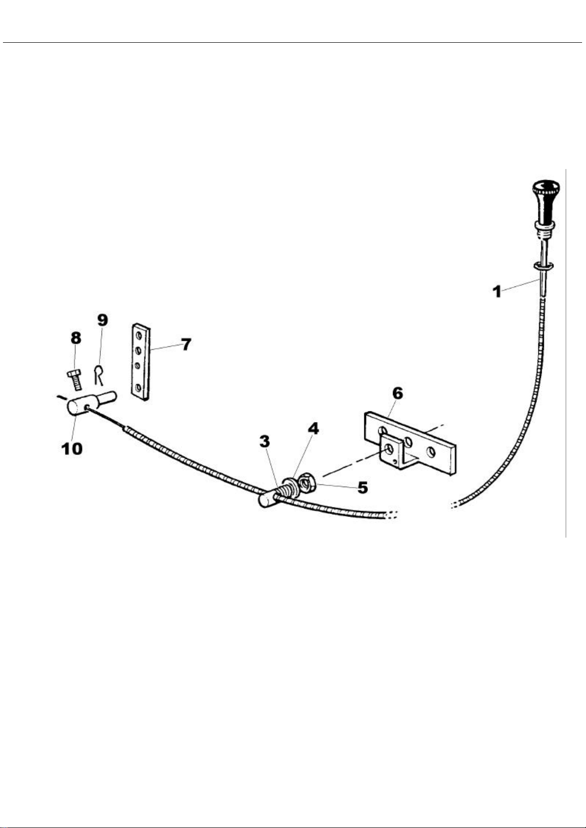
400R TR2 ENGINE STOP CABLE
Page 94

400R TR2 ENGINE STOP CABLE
1 460239 CABLE STOP 1
3 460242 SCREW CLAMP, OUTER CABLE 1
4 67S04 WASHER SHAKEPROOF 1
5 87S03 NUT BINX 1
6 11029A01 BRACKET RETAINING 1
7 11030A01 LEVER PIVOT 1
8 V600192 SCREW SET 1
9 V600193 R CLIP 1
10 V600194 FITTING SWIVEL, INNER CABLE RETAINING 1
PARTS NOT ILLUSTRATED
11 555292300 BRACKET, CABLE STOP 1
12 11S02A SCREW SET 2
13 267S04 WASHER FLAT 4
14 61S02 NUT BINX 2
15 143200900 CLIP NYLON 1
16 16S05B SCREW SET 1
17 267S02 WASHER FLAT 1
18 17S10 WASHER SPRING 1
19 7S09 NUT 1
Page 95
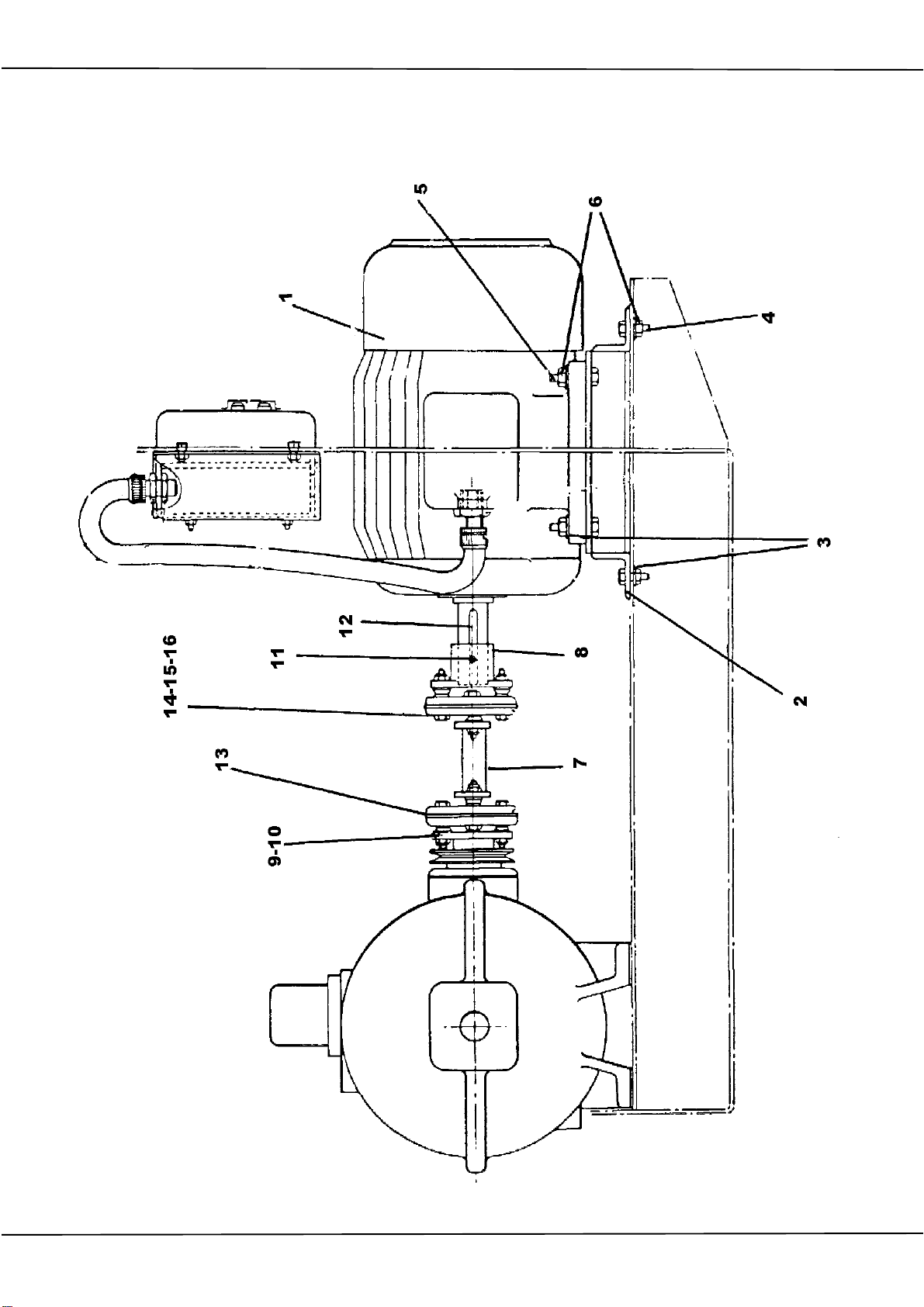
400R 11KW MOTOR AND DRIVE SHAFT 415 VOLT
Page 96

400R 11KW MOTOR AND DRIVE SHAFT 415 VOLT
1 202424000 MOTOR ELECTRIC 11 KW 1
2 555145400 MOUNTING MOTOR 1
3 10S04 WASHER FLAT 8
4 28S05G SETSCREW 4
5 6S05E SETSCREW 4
6 87S05 NUT BINX 8
7 555142600 SHAFT CONNECTING 1
8 555145500 FLANGE DRIVE 1
9 555258100 ADAPTOR DRIVE 1
10 90S04H SCREW CAP 4
11 195S03C2 SCREW GRUB 1
12 304712863 KEY 1
13 130972000 COUPLING LAYRUB 2
14 8S05H BOLT 8
15 267S07 WASHER FLAT 8
16 61S05 NUT BINX 8
ITEMS 14-15-16 ARE SUPPLIED WITH LAYRUB COUPLING ITEM 13.
Page 97
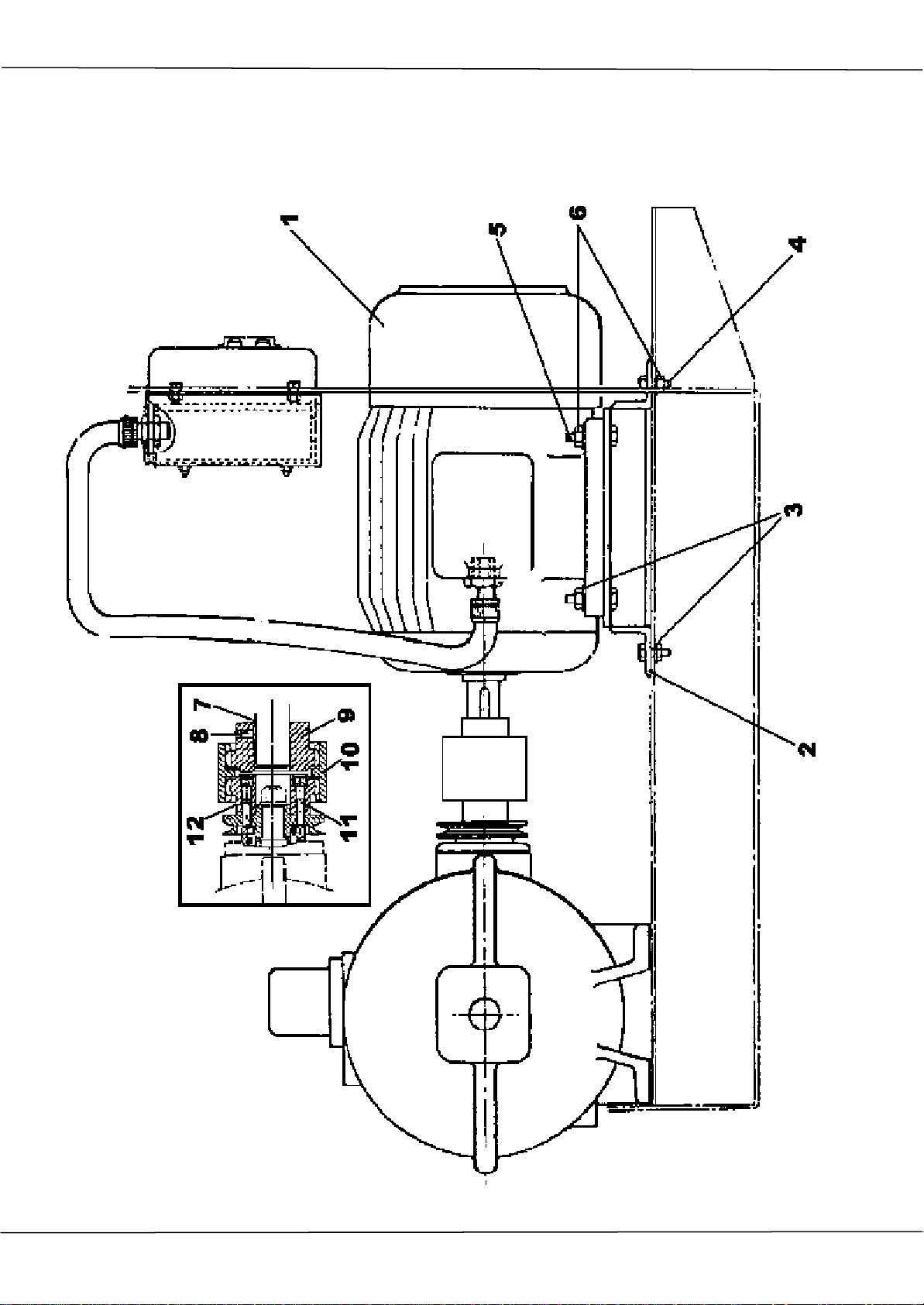
400R 11KW 415V MOTOR AND DRIVE SHAFT LATER TYPE
Page 98

400R 11KW 415V MOTOR MOUNT DRIVE SHAFT LATER TYPE
1 202424000 MOTOR ELECTRIC 11 KW 1
2 555145400 MOUNTING MOTOR 1
3 10S04 WASHER FLAT 8
4 28S05G SETSCREW 4
5 6S05E SETSCREW 4
6 87S05 NUT BINX 8
7 304712863 KEY 1
8 188S04E1 SCREW GRUB 1
9 555291700 COUPLING MOTOR 1
10 147320001 COUPLING SLEEVE NYLON 1
11 90S04L SCREW SOCKET HEAD CAP 4
12 555248601 COUPLING GEARBOX 1
Page 99
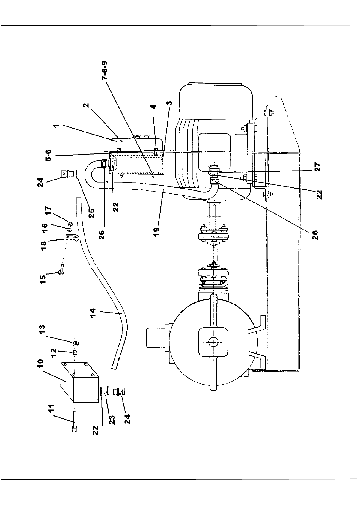
400R STARTER AND STOP SWITCH 415 VOLT
Page 100

400R STARTER AND STOP SWITCH
1 208304103 SWITCH STARTER 1
2 208304104 RELAY OVERLOAD 14A-21A 1
3 555144200 BRACKET STARTER 1
4 6S03B BOLT 4
4A CSE182 SPACER (USED TO MOVE BRACKET AWAY FROM MOTOR) 4
5 41S05 WASHER SPRING 4
6 9S03 NUT 4
7 11S02A SCREW SET 4
8 17S03 WASHER SPRING 4
9 7S02 NUT 4
10 20887000 SWITCH STOP C/W KEYS 1
11 103S02D SCREW SKT CAP 2
12 41S03 WASHER SPRING 2
13 104S01 NUT 2
14 131770010 CONDUIT 1.5 MTR LONG 1
14A 1444700200 WIRE EARTH GREEN/YELLOW 2MT
14B 144700100 WIRE RED 4MT
15 11S02C SCREW SET 2
16 17S03 WASHER SPRING 2
17 7S02 NUT 2
18 V2004640 CLIP "P" NORMA 22MM 2
19 131736000 CONDUIT ( I MT LONG) 1
20 030788102 WIRE RED 6MT
21 030788103 WIRE EARTH GREEN/YELLOW 1MT
22 133275050 NUT LOCK THIN 3
23 131575020 REDUCER 1
24 131271000 COUPLING KOPEX 2
25 56S07 NUT LOCK THIN 1
26 131272000 COUPLING KOPEX 2
27 131592025 CONVERTER PG29-M25 1
 Loading...