

Winget 100T, 150T, 175T Workshop Manual
WORKSHOP MANUAL
100T, 150T & 175T
HANDFED MIXERS
WINGET LIMITED
PO BOX 41
EDGEFOLD INDUSTRIAL ESTATE
PLODDER LANE
BOLTON
LANCS
BL4 OLR
Tel: ++ 44 (0) 1204 854650
Fax: ++ 44 (0) 1204 854663
service@winget.co.uk
parts@winget.co.uk
www.winget.co.uk
ISSUE 9 2015

WORKSHOP MANUAL
100T / 150T / 175T
Winget Concrete Mixers
From 1988 Onwards
Issue 9 2015
CONTENTS
Section 1 Introduction
Section 2 Repair and Service Procedures
Section 3 General Arrangement Dimensions
Section 4 Service Schedules
Section 5 Lubrication Diagram
Section 6 Wiring Diagrams
Section 7 Noise Levels
Section 8 Special Tools
Section 9 Parts Listings

WORKSHOP MANUAL
100T, 150T & 175T
SECTION 1
INTRODUCTION

WORKSHOP MANUAL
100T / 150T / 175T
Winget Concrete Mixers
From 1988 Onwards
Issue 9 2015
Introduction
It is assumed that personnel involved in either the assembly or repair of Winget
Mixers will be familiar with the product, either through the operation of, or
previous repair and maintenance work. It is not intended to be used by
personnel who are neither familiar with the product nor mechanically
inexperienced.
It is also assumed that personnel are aware of Health and Safety Regulations,
which should be applied to all working practices but the following should act as a
reminder.
Ensure all work tools are in good condition.
Always wear Safety Spectacles when using soft or hard faced hammers, chisels
or when using air tools. Wear Safety Spectacles when cleaning hardened
concrete or mortar deposits off components. Do not misuse airlines and be
aware of the damage compressed air can cause if misused.
Always make sure lifting equipment is in good condition and the marked Safe
Working Loads exceed the weights of the components to be lifted.
Oils, fuels, silicone sealers and open gear lubricants can cause skin diseases if
allowed to contaminate the skin. Always apply barrier creams, wear suitable
protective clothing, or when contamination is unavoidable clean the area with
soap and water as soon as possible. Do not use thinners or other solvents to
clean skin.
Health and Safety is a matter of common sense. If common sense is applied
correctly Health and Safety can be improved and the risk of accidents reduced.
L/H and R/H views are taken when standing directly behind and facing the
engine housing.
Refer to the Parts Books for a guide to the correct sequence for assembling
components and sub-assemblies.
Whilst every effort is made to ensure the contents of this manual are accurate,
Winget Limited reserve the right to altar specification without prior notification and
certain sections may then no longer apply.

WORKSHOP MANUAL
100T, 150T & 175T
SECTION 2
REPAIR & SERVICE
PROCEDURES

WORKSHOP MANUAL
100T / 150T / 175T
Winget Concrete Mixers
From 1988 Onwards
Issue 9 2015
Repair & Maintenance Procedures
The following procedures are based in part on the procedures issued to
Distributors and the instructions should be used in conjunction with the
appropriate Parts and Operators Manual or CD ROM. Reference should also be
made to the Parts Listings in Section 9 for a guide to the correct sequence for
assembling components and sub assemblies.
1) Clean any paint or debris from bores and shaft surfaces. Threaded holes
should preferably be cleaned out using the correct tap
2) All sealed for life bearings should be packed with a good quality grease
prior to installation. Carefully remove a seal, pack the bearing with grease
and refit the seal ensuring it is correctly seated.
3) Apart from installing the electric motor, mounting brackets and conduit as
described in this manual under the heading ‘110 volt & 240 volt single
phase Electric Motor.’ All wiring and other work concerned with the
installation of 110 volt and 240 volt components and supply should be left
to a suitably qualified electrician, who is conversant with single phase
electric circuits.
4) The PTO of the Honda GX160K1 LX4 Petrol engine rotates anti-
clockwise whilst the Lister-Petter LT1/LV1, AC1-05, YANMAR L40/L48
ARE SE and the 240/110V electric motors all rotate clockwise. Therefore
the drum blades and countershaft and sprocket fitted to Honda powered
mixers are ‘OPPOSITE HAND’. When ordering spares it is important that
the correct part number and engine type are quoted. Blades, countershaft
and sprockets intended for use with the Lister-Petter and Yanmar should
not be used with Honda powered mixers and vice-versa.

WORKSHOP MANUAL
100T / 150T / 175T
Winget Concrete Mixers
From 1988 Onwards
Issue 9 2015
Lifting Points
A lifting point capable of supporting the weight of the mixer is incorporated into
the trunnion.
This lifting point is highlighted with an ISO ‘Hook’ symbol adjacent to the point.
On Military/NATO mixers the lifting point will also be painted white.
Draw Bar Replacement-Four Wheel Tow
The drawbar is secured to the front axle using split pins and flat washers.
Remove the split pins and flat washers slide the old drawbar out of the lugs on
the front axle. Replacement is a reversal of the above procedures ensuring that
the eye on the drawbar points downwards.
Wheel Replacement-Four Wheel Tow
Solid rubber cushion and steel wheels are secured using split pins and flat
washers and the removal procedure is identical. Lift and support the axles.
Remove the split pins and washers. Clean the axle shafts and coat with
copperslip. Fit the new wheel replace the flat washer and secure using a new
split pin.
Wheel Replacement-Two Wheel Tow
On two wheel tow mixers the pneumatic tyre/wheel assembly is secured to the
hub/suspension unit by four nuts. To change a wheel, chock the wheel on the
opposite side, slacken but do not remove the wheel nuts securing the wheel to
be changed. Place a suitable jack below the suspension unit and jack up the
mixer until the tyre is just clear off the ground, remove the nuts and wheel
assembly. Reverse the procedure to refit and fully tighten the wheel nuts when
the jack is removed.
It is recommended that the wheel nuts be rechecked following a short “road test”
Hub/Suspension Unit Replacement-Two Wheel Tow Mixers
The suspension units require no maintenance being a sealed unit having an
internal construction of rubber and ends sealed with nylon bushes. Suspension
units should not be subjected to heat such as welding or oxy-acetylene cutting as
this will damage the rubber and nylon components.

WORKSHOP MANUAL
100T / 150T / 175T
Winget Concrete Mixers
From 1988 Onwards
Issue 9 2015
The suspension units are secured to the mainframe using six/eight bolts and nuts
to remove, slacken the wheel nuts, jack up and support the mainframe on
suitable supports. Do not attempt to work under the mainframe if it is supported
only on a jack. Remove the wheel nuts and wheel assembly. Unbolt and remove
the mudguard and supporting bracket. Remove the remaining bolts securing the
suspension unit and detach the unit from the mainframe.
Note: it is recommended that suspension units be replaced in pairs.
Reverse the procedure to refit.
Wheel Hubs & Bearings-Two Wheel Tow
A single castle nut and flat washer retains the hubs to the stub axles of the
suspension units. The castle nut is also secured with a split pin; this is accessible
after removing the steel/plastic dust cap.
There are two types of hub bearings in use dependent on the age of the
machine: -
The early type with ball race bearings and spacer, with this type the retaining nut
must be fully tightened.
The later automotive type taper roller bearings requiring a small amount of end
float.
To remove the hubs remove the wheels as described above, prise off the dust
caps. Remove the split pin, nut and washer and pull off the hub. Do not allow the
taper roller or ball bearings to drop to the floor where they will become
contaminated with dust etc. The later type inner taper roller bearing and seal unit
will normally be left on the stub axle when the hub is withdrawn, this can be
carefully tapped off using a suitable drift taking care not to damage the bearing
cage.
Clean all traces of old grease out of the hubs and off the stub axles, using a
suitable drift knock out the old bearings, pack the new bearings with grease and
tap home into the hub.
Assemble the hub and bearings onto the stub axle, in the case of the ball race
bearings and spacer fully tighten the nut and insert the locking split pin. Check
the hub rotates freely and fit the dust cap. Charge the hub with grease until the
grease is visible in the breather hole in the cap.

WORKSHOP MANUAL
100T / 150T / 175T
Winget Concrete Mixers
From 1988 Onwards
Issue 9 2015
With taper roller bearings, tighten the nut then back off 1/4-1/2 a turn, check that
the hub spins freely without to much end float, .004” is sufficient. Align the castle
nut with the split pinhole in the stub axle and fit the retaining split pin. Recheck
the hub rotates freely and refit the dust cap. Charge the hub with grease until the
grease is visible in the breather hole in the cap.
It is recommended that the wheel bearing adjustment be rechecked after giving
the mixer a short “road test”.
Front Axle Replacement- Four Wheel Tow
Depending on the age of the mixer two different front axle assemblies are fitted.
Early Mixers
Early mixers have a swivel fitted to the front axle, which allows the axle to
oscillate as well as rotate.
Jack up and support the mainframe so the front wheels are clear of the ground.
Remove the circlips securing the pivot pin through the front axle and swivel
bracket. Knock out the pivot pin and remove the axle. The swivel bracket is
secured to the mainframe by a spiral pin, using a suitable drift knock out the pin
and remove the swivel.
Replacement is a reversal of the above procedure however pins and shafts
should be coated with copperslip on assembly. When fitting the spiral pin
through the swivel bracket rotate the bracket through a full 360 degrees making
sure the pin does not foul the mainframe. Fit new circlips and split pin.
Early 175T mixers have a separate bracket bolted to the mainframe into which
the swivel is located. This is secured using four nuts, bolts and washers and can
be removed once the axle and swivel have been removed as described above.
Replacement is a reversal of this procedure.
Later Mixers
On later Mixers the front axle only rotates through 360°, it will not oscillate and
the front axle now locates directly into the front leg of the mainframe where it is
secured via a spiral pin.
Jack up and support the mainframe and knock out the spiral pin. Remove the
axle. Replacement is a reversal of the procedure however the pivot pin and axle
shafts should be coated with copperslip. The axle should be rotated through
360° degrees making sure the spiral pin does not foul the mainframe.

WORKSHOP MANUAL
100T / 150T / 175T
Winget Concrete Mixers
From 1988 Onwards
Issue 9 2015
Rear Axle-Four Wheel Tow
Early 175T mixers have a separate rear axle bolted to the mainframe. Jack up
and support the mainframe with the rear wheels clear of the ground. Remove the
nuts, bolts and washers securing the axle to the mainframe and remove the axle
assembly.
Replacement is a reversal of the above procedure.
Drum Removal
Attach suitable lifting equipment through the drum blades. Knock back the tabs
on the lock-washer securing the drum shaft setscrews. Remove the setscrews
and the washers securing the shaft and flange. With the drum mouth upright lift
the drum assembly clear of the trunnion. It may be necessary to rock the trunnion
via the tiltwheel to free the shaft, especially if the mixer has been in service for
some time.
In exceptional circumstances it may be necessary to use a commercially
available two-leg puller/pusher tool to assist in pushing the drum shaft through
the trunnion. When using such tools please ensure the manufacturers or
supplier’s instructions are adhered to.
Drum Re-Fitting
Clean and lubricate both the drum shaft and trunnion base plates with copperslip.
Coat the bevel pinion and bevel gear with open gear lubricant. Attach suitable
lifting equipment through the drum blades; lift the drum assembly and position
over the trunnion.
Turn the drum shaft so the threaded holes in the shaft are at 90° to the holes in
the lower base plate. Lower the drum and shaft assembly into place making sure
that the bevel gear and pinion are fully in mesh and the drum shaft is fully
through the base plates.
Slip the lockwasher over the two drum shaft setscrews and coat the threads with
copperslip, using the setscrews secure the flange to the shaft. The flange can be
used to turn the shaft until the remaining holes in the flange align with the
remaining holes in the lower base plate.
Check the number of flat washers required to pack the gap between the flange
and lower base plate. (See “A” on the following illustration). Deduct one washer
from each side. Coat the threads on the setscrews with copperslip and fit the
setscrews with spring washers attached through the flange and flat washers and
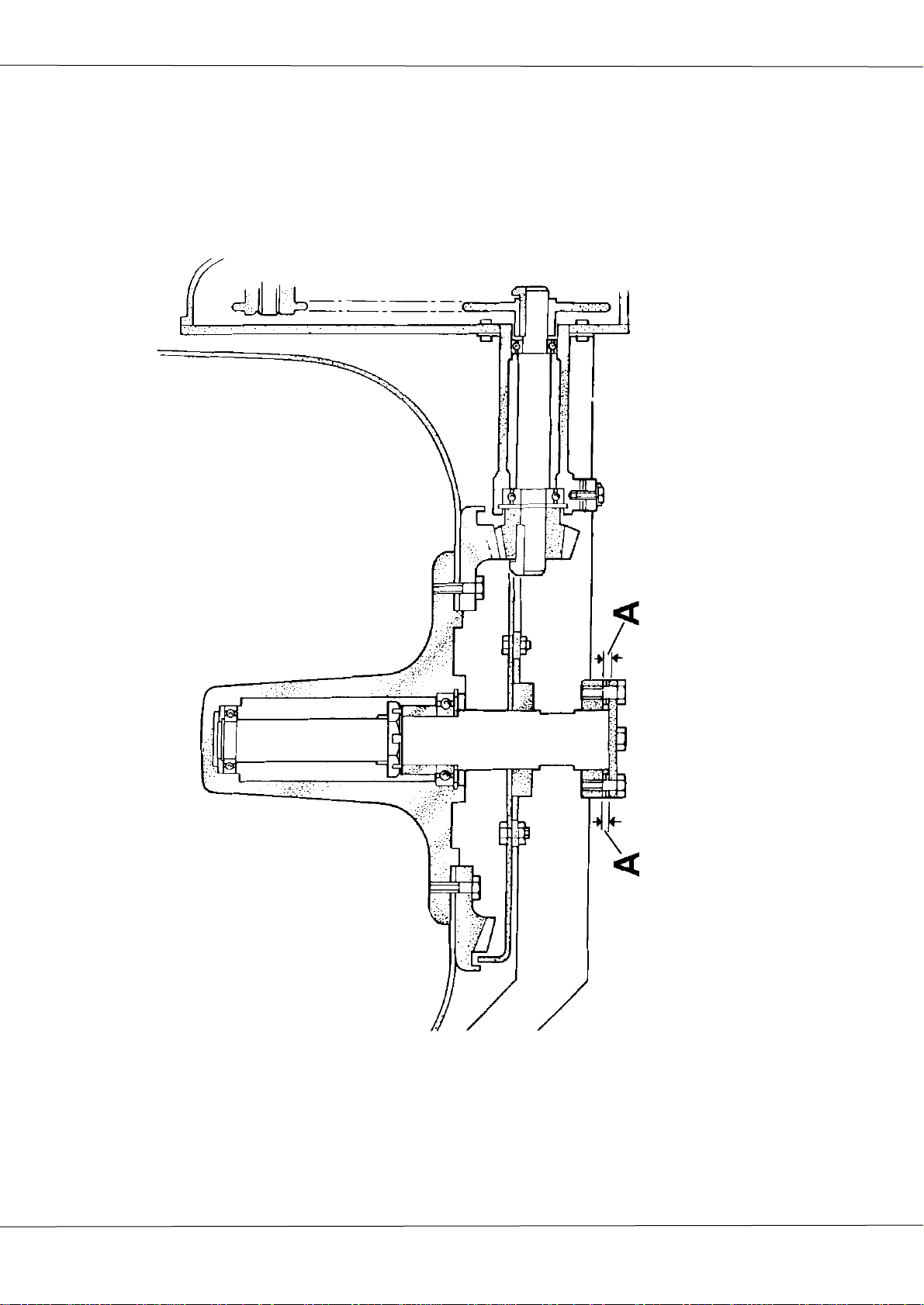
100T 150T 175T DRUM DRIVE LAYOUT

WORKSHOP MANUAL
100T / 150T / 175T
Winget Concrete Mixers
From 1988 Onwards
Issue 9 2015
tighten into the base Plate. This will lift the drum shaft slightly back through the
trunnion increasing the distance between the teeth of the bevel pinion and bevel
gear. Gently rock the drum assembly back and forth and check the backlash
between the gears. (Approx 5mm measured at drum clip). Ensure the setscrews
are tight and knock over the tabs on the lockwasher.
Drum Cone Replacement
NOTE: the drum on Honda powered mixers rotates anti-clockwise on all others
the rotation is clockwise.
Clean hardened concrete or mortar deposits from around the drum clip and the
bolts securing the drum blades. Remove the bolts securing the blades to the
drum cone and slacken the bolts through the base. Cut through the drum clip and
remove. Lift off the drum cone.
If necessary clean out the drum base. Clean old silicone sealer and hardened
concrete from the drum flange otherwise it will be difficult to effect a good seal
when the new cone is fitted.
Run a generous bead of silicone sealer around the flange and inside the new
drum clip. Leave the last 150mm of each end of the clip free from sealer.
Using suitable lifting equipment lift the new drum cone in place lining up the holes
in the cone with those in the blades. Loosely refit in the bolts, nuts and washers.
Fit the new drum clip around the circumference of the two halves of the drum
tapping in place over the flanges using a soft faced hammer.
Attach the special drum clip tool; available under part number 513204000 from
your local Winget distributor, placing the pins of the tool into the holes in each
end of the clip. (Refer to the illustration)
Using a suitable spanner tighten the drum clip to the drum until it is secure. Do
not overtighten the clip or the pins in each end of the tool will shear off. Slip the
bridge piece over the remaining gap in the drum clip and weld in place. Remove
the tool and fully tighten the drum blades.
Run the mixer, tilting the drum via the tiltwheel making sure that the drum, clip or
bridge piece, do not foul the mainframe or guards. Check the watertight integrity
of the drum by emptying a bucket of water into the drum whilst the drum is tilted
and the engine is running and observe if water leaks around the clip are evident.
If leaks are evident run a bead of silicone around the interior joint between the
two halves of the drum.
Stop the engine; clean any excess silicone off the drum or clip.
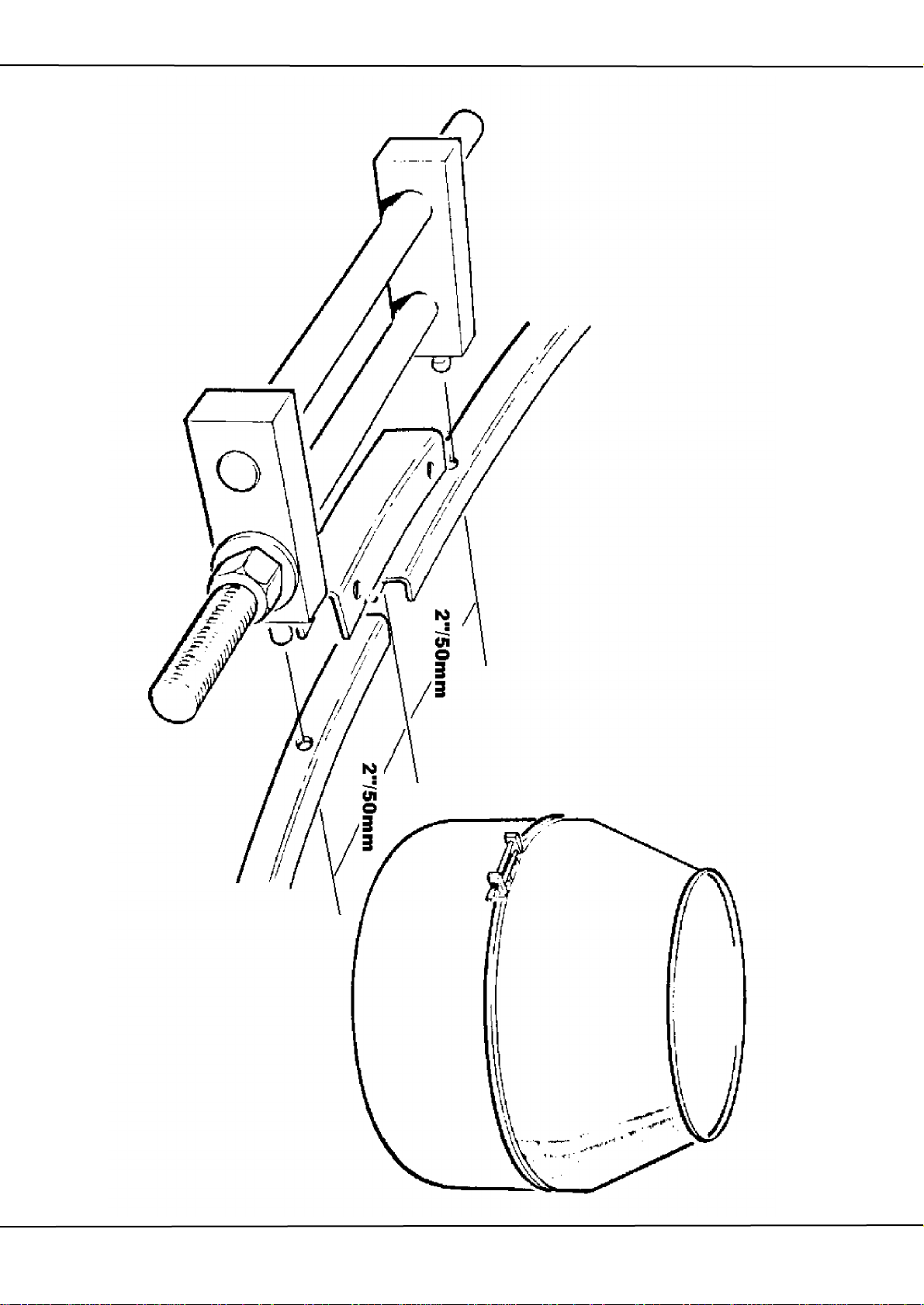
100T 150T 175T DRUM CLIP FIXING
IN PLACE
PLACE OVER THE GAP LEFT IN THE CLIP AND WELD
NUMBER 513204000. FIT THE BRIDGE PIECE IN
THE CLIP IN PLACE USING THE SPECIAL TOOL
EACH END OF THE CLIP CLEAR OF SEALER. CLAMP
FITMENT LEAVING APPROXIMATELY 6’’ (I50mm)
OF SEALER INSIDE THE DRUM CLIP PRIOR TO
CLIP AROUND THE DRUM AS SHOWN. RUN A BEAD
BASE AND CONE WITH SILICONE SEALER FIT THE
AFTER COATING THE MATING FACES OF THE DRUM

WORKSHOP MANUAL
100T / 150T / 175T
Winget Concrete Mixers
From 1988 Onwards
Issue 9 2015
Drum Blade Replacement
NOTE: the drum on Honda powered mixers rotates anti-clockwise. on all others
the rotation is clockwise, therefore Honda powered mixers use different blades.
It is unlikely that drum blades will require replacement separately to the drum
cone. However in the event that it should prove necessary, clean any hardened
concrete or mortar deposits from around the bolts securing the blades. Remove
the bolts and blades. Due to the corrosive action of concrete and mortar it may
be necessary to cut through the old bolts using oxyacetylene equipment. Be
aware that hot concrete can “explode” violently spitting concrete - wear suitable
eye protection and protective clothing.
Attach the new blades into the drum assembly finger tighten the bolts until all the
bolts are in place. Tighten the bolts.
The bolts should go into the drum from the outside and only round headed bolts,
either slotted or hexagon key should be used.
Bevel Gear Guard Replacement
Remove the drum assembly as previously described. Remove the four
setscrews, nuts, etc. holding the guard in place. Fit the new guard tighten the
setscrews. Replace the drum assembly as previously described.
Bevel Gear Replacement
Remove the drum assembly as previously described. Turn the drum so that it
stands on the drum mouth, support the centre housing on the inside of the drum
or attach lifting equipment to the drum shaft so that the centre housing cannot fall
inside the drum when the bevel gear is removed.
Release the lockwashers and remove the setscrews securing the bevel gear,
prise off the bevel gear and clean down the surface of the drum ready to accept a
replacement. Fit the new bevel gear, slip new lockwashers on to the setscrews,
coat the threads with copperslip and enter through the bevel gear into the centre
housing.
Turn the tang on the lockwashers so that the tang can be turned down the inside
of the bevel gear. Tighten the setscrews and bend the rounded edge of the
lockwashers over the flats on the head of the setscrews. Coat the bevel gear with
open gear lubricant. Refit the drum assembly as previously described.

WORKSHOP MANUAL
100T / 150T / 175T
Winget Concrete Mixers
From 1988 Onwards
Issue 9 2015
Drum Shaft, Bearings and Drum Centre
Remove the drum assembly as described previously. Lay the drum assembly on
its side and release the lockwashers. Support the centre housing and remove the
setscrews, which pass through the bevel gear and prise off the bevel gear.
Carefully lower the centre housing into the drum. Lift the Housing out of the
drum and clean down the mating surfaces in the drum removing all traces of the
old gasket and sealer.
Clean the centre housing prior to any further dismantling. Remove the large
circlip from the groove within the centre housing and using a suitable tool pull the
drum shaft assembly out of the housing. If a suitable tool is not available secure
the drum shaft in a soft jawed vice and using a soft faced hammer knock the
housing off the shaft taking care not to damage the housing. Clean any debris
out of the housing and inspect for damage.
Secure the drum shaft upright in a soft jawed vice remove the upper circlip and
bearing. Release the lockwasher and remove the nut, lockwasher and distance
piece. Remove the lower bearing.
Before fitting new bearings carefully remove the seals from the bearings and
pack the bearings with good quality grease, refit the seals, do not completely fill
the bearings with grease leave some room for expansion as the grease warms
up in service.
Re-assemble the shaft in reverse order making sure the lockwasher is correctly
fitted and locked onto the nut.
Smear the circumference of the bearings with copperslip and using a soft faced
hammer knock the shaft assembly fully home into the housing. Refit the circlip
into the groove within the housing.
Place a new gasket over the housing, locate the housing assembly into the drum
and temporarily support in place.
Refit the bevel gear as previously described. Remove the supports from below
the centre housing inside the drum. Refit the drum assembly as previously
described.
Tilting Wheel and Locking Plunger
The tilting wheel is secured to the tilting pinion via a spiral pin, later versions also
have an additional M10 grubscrew. With the drum in the vertical position knock
out the spiral pin, slacken the grubscrew, if fitted, and pull off the tilting wheel.

WORKSHOP MANUAL
100T / 150T / 175T
Winget Concrete Mixers
From 1988 Onwards
Issue 9 2015
The locking plunger is held in place in the tilting wheel by a second smaller spiral
pin. Knock out this pin and remove the locking plunger and spring.
Re-assemble in the reverse order coating the locking plunger and pinion shaft
with copperslip. Lubricate the felt seal behind the tilting wheel with oil.
Note: Later larger diameter tilting wheels also have an M10 grub screw fitted in
addition to the spiral pin.
Tilting Bracket
With the drum in the vertical position, place temporary supports between the
mainframe and trunnion to support the trunnion when the tilting bracket is
removed.
Remove the upper tiling gear guard. Remove the four socket headed capscrews
securing the tilting bracket taking care not to drop the retaining bracket on the
inside of the mainframe front leg. Pull off the tilting bracket assembly. Check the
felt seal in the tilting gear replace and/or lubricate as required.
Knock out the spiral pin securing the tilting wheel to the tilting pinion. Pull off the
tilting wheel and pull the pinion out of the bracket. Check the condition of the
bushes and felt seals. Replace and/or lubricate as required. The stub shaft is
also secured into the tilting bracket via a spiral pin and can be removed simply by
knocking out the pin.
Reassemble the tilting bracket in reverse order lubricating bushes and felt seals
with engine oil. Coat shafts, pinions and plungers with copperslip.
When refitting the tilting bracket assembly to the mixer, engage and lock the
plunger into the middle of the three bushed blind holes. Locate the stub shaft into
the tilting gear and ensuring that the tilting pinion correctly meshes with the tilting
gear push the assembly fully home. Coat the threads on the four capscrews with
thread lock, insert through the tilting bracket, mainframe and into the retaining
bars which should be held in position until the capscrews are engaged. Tighten
the capscrews. Check that with the drum vertical that the cross ties on the tilting
wheel are horizontal. Refit the upper tilting gear guard. Remove the temporary
supports.
Tilting Gear and Lower Guard
Remove the tilting bracket as described previously. Undo and remove the four
setscrews securing the guard to the mainframe. Undo and remove the four nyloc

WORKSHOP MANUAL
100T / 150T / 175T
Winget Concrete Mixers
From 1988 Onwards
Issue 9 2015
nuts and flat washers holding the gear. Push the bolts back through the gear,
slide the gear forward and lift clear of the mainframe. Lift off the lower guard.
Reassemble in reverse order not forgetting to put the guard behind the gear.
Lubricate the felt seal.
Refit the tilting bracket as previously described.
Countershaft/Bevel Pinion Drive Chain.
Remove the chain guard from the rear of the trunnion. Crank the engine over
until the chain split link is visible. Disconnect the link. Hook the new chain
loosely onto the split link and slowly crank the engine pulling the new chain in
place round the countershaft chain wheel. Remove the old chain and link. Loop
the new chain round the chain wheel on the bevel pinion shaft and fit the new
split link. The open end of the split end should point away from the normal
direction of rotation, which is anti-clockwise when looking directly at the chain,
clockwise on Honda powered mixers. Check and adjust the chain tension. (See
bevel pinion shaft and housing). Refit the chain guard.
Bevel Pinion Shaft and Housing
Follow the procedures described earlier and remove the drum, bevel gear guard
and disconnect the countershaft bevel pinion drive chain.
Rotate the trunnion until it reaches its highest point and lock in place. Remove
the gib head key securing the chain wheel to the bevel pinion shaft. Remove the
bevel pinion guard, release the lockwashers and remove the setscrews, packers
and shims securing the bevel pinion housing. At this point the housing should
either be supported by a second pair of hands, strapped or supported in some
other manner to prevent it dropping down sharply and causing damage to the
casting, it will otherwise only be secured by the loose fitting retaining plate and
chain wheel.
Remove the nuts and washer from the two bolts retaining the bevel pinion
housing adjusting plate. Using a soft faced hammer knock the bevel pinion shaft
through the chain wheel until it is possible to remove the chain wheel. Remove
the bolts through the retaining plate and lift the housing out of the trunnion.
Clamp the housing in a soft jawed vice and remove the gib head key retaining
the bevel pinion and pull off the pinion.

WORKSHOP MANUAL
100T / 150T / 175T
Winget Concrete Mixers
From 1988 Onwards
Issue 9 2015
Remove the circlip from the groove within the housing and using a soft faced
hammer knock the shaft and bearings out of the housing. The bearings can now
be removed from the shaft.
Before fitting new bearings carefully remove the seals from the bearings and
pack the bearings with good quality grease, refit the seals, do not completely fill
the bearings with grease leave some room for expansion as the grease warms
up in service.
To reassemble secure the bevel pinion shaft into a soft jawed vice. Using the
correct size of bearing tube and a soft faced hammer fit the bearings to the shaft.
Note the larger of the two bearings is fitted to the longer shank of the shaft.
Remove the shaft from the vice and using the vice support the bevel pinion
housing. Using the correct size of bearing tube and the soft faced hammer knock
the shaft fully into the housing. Fit the retaining circlip into the groove within the
housing and check the shaft turns freely.
Assemble the bevel pinion to the shaft, fitting the gib head key. The pinion is
fitted to the longer shank of the shaft. If correctly assembled the threaded holes
in the casting will be at the same end. Do not at this stage fit the chain wheel to
the opposite end of the bevel pinion assembly, as this will prevent reassembly of
the housing into the trunnion.
Loosely fit the triangular adjusting plate back into the trunnion, locating the plate
on the peg. Fit the two bolts through the adjusting plate from the rear of the
trunnion so that when assembled the head of the bolts will be sandwiched
between the trunnion rear plate and the chain wheel.
Work the bevel pinion housing back into the trunnion and through the adjusting
plate. As the shaft protrudes through the rear of the trunnion slide on the chain
wheel until it is fully home.
Refit the setscrews, lockwashers, packer and shim set retaining the bevel pinion
housing and finger tighten only.
Fit the gib head key retaining the chainwheel and refit the drive chain, when
connecting the split link the open end of the link should be fitted so that it points
away from the normal direction of rotation which is anti-clockwise when looking
directly at the chain, clockwise on Honda powered mixers.
Release the trunnion and turn back to its lowest position. The adjusting plate
holding the rear of the bevel pinion housing is slotted to allow the housing to
move up and down enabling correct adjustment of the chain tension. Check and
adjust the chain and tighten the two bolts securing the adjusting plate. By adding

WORKSHOP MANUAL
100T / 150T / 175T
Winget Concrete Mixers
From 1988 Onwards
Issue 9 2015
or subtracting shims between the thick packer and housing ensure the housing is
horizontal in the trunnion and square to the rear plate. Re-check the chain
tension and fully tighten the bolts and setscrews securing the housing, knock
over the lockwashers.
Crank the engine ensuring both the countershaft and bevel pinion turn freely.
Coat the bevel pinion with grease or open gear lubricant and fit the pinion guard.
Fit the rear chain guard folding the tab over the trunnion.
Following the procedures described earlier refit the bevel gear guard and drum
assembly.
Countershaft, Trunnion Journal, Bearing Housing & Driven Chain wheel/
“V” Belt Pulley
Although it is recommended that the trunnion be removed completely from the
mixer should the countershaft, trunnion journal or bearing housing require
attention it is possible to leave the trunnion assembly in place provided it is
properly supported.
Remove the drum as described previously. Remove the engine housing lid (top
plate on 175T), engine housing chain guard and trunnion chain guard.
Disconnect both drive chains.
On 110/240v electric drive, Lister-Petter AC1-05, Yanmar L40/L48 electric start
diesel and Honda Petrol mixers the drive is transmitted to the countershaft by
means of a ‘V’ belt in place of the chain.
Remove the six setscrews securing the trunnion bracket to the engine housing,
remove the four countersunk socket headed screws and lift off the trunnion
journal assembly.
Support the assembly in a soft jawed vice, remove the gib head key retaining the
countershaft chain wheel and remove the chain wheel. Lift off the trunnion
bracket; carefully remove the trunnion bearing and strip out the “O” rings and
nylatron strip.
Using a soft faced hammer knock the countershaft out of the trunnion journal.
Remove the bearing and circlip from within the journal housing.
Secure the countershaft in a soft faced vice, remove the grubscrew and unscrew
the chain wheel, remove the bearing. Note: On mixers fitted with Lister-Petter
LT1/LV1, Yanmar L40/L48 and 240/110V the countershaft and chain wheel have
a LH thread, on Honda powered mixers the thread is RH.

WORKSHOP MANUAL
100T / 150T / 175T
Winget Concrete Mixers
From 1988 Onwards
Issue 9 2015
Reassembly
Fit the circlip into the groove within the trunnion journal and lubricate the outer
circumference/bearing face with copperslip.
Insert the nylatron bearing strip into the trunnion bearing, fit the “O” rings into
their respective grooves within the bearing housing and pack the “O” ring
grooves and nylatron bearing with grease. (Refer to the illustration to identify the
“O” rings and their location)
Carefully fit the trunnion bearing over the trunnion journal taking care not to
dislodge the “O” rings or damage the trunnion bearing.
Before fitting new bearings carefully remove the seals from the bearings and
pack the bearings with good quality grease, refit the seals, do not completely fill
the bearings with grease leave some room for expansion as the grease warms
up in service.
Secure the countershaft in a soft jawed vice and using the correct size of bearing
tube and a soft faced hammer fit the larger of the two bearings to the threaded
end of the countershaft. Apply threadlock to the threads and screw on and
tighten the countershaft chain wheel. Peen the end of the shaft in four points as
an additional precaution to prevent the chain wheel unscrewing. Fit the
grubscrew coating the threads with threadlock.
Insert the smaller bearing into the journal making sure it seats against the circlip.
Support the trunnion journal/trunnion bearing assembly in a soft jawed vice and
using a soft faced hammer knock the countershaft assembly into the journal
taking care not to dislodge the lower bearing. Remove the completed assembly
and check the countershaft turns freely. Feed the short drive chain onto the
countershaft chain wheel.
Coat the threads on the countersunk socket headed screws with threadlock and
secure the assembly onto the face of the trunnion.
Turn the trunnion bearing so that the machined slot is at 12 o'clock and locate the
trunnion bracket, fit the six setscrews and tighten.
Refit the drum assembly, countershaft chain and guard as previously described.
Coat the countershaft inside the engine housing with copperslip, fit the chain
wheel and gib head key. Reconnect the engine drive chain or alternatively the ‘V’
belt.
100T 150T 175T 'O' RING LOCATION
49S41
49S42
ON ASSEMBLY
PACK ‘O’ RING CAVITIES
AND NYLATRON
BEARING WITH GREASE

WORKSHOP MANUAL
100T / 150T / 175T
Winget Concrete Mixers
From 1988 Onwards
Issue 9 2015
Refit the chain guard not forgetting the polythene plug, engine housing lid and
top plate on the 175T.
Start the engine and run test checking for unusual noises.
Engine, Lister-Petter LT1/LV1-32 (100T & 150T) Lister-Petter LT1/LV1-10
(175T) PTO Shaft Clockwise Rotation.
“CE” marked machines are fitted with ‘anti-kick back starting handles’ in order to
comply with European legislation. For information on the starting handles refer to
the engine operators handbook or engine workshop manual.
For details on engine services or overhauls, changing engine oils, filters and
bleeding the fuel system refer to the engine operator’s handbook or engine
workshop manual.
Note, the Lister-Petter LT1/LV1 engine is set to run at 900/1000 rpm and rotates
clockwise at the flywheel end.
Engine Sprockets LT1/LV1
The engine sprockets on LT1/LV1-32 engines are secured to the flywheel via the
flywheel retaining screw. On the LT1/LV1-10 the sprocket is keyed onto the
engine extension shaft and also held by an M8 grubscrew. Replacement of either
sprocket requires removal of the engine.
Remove the engine housing closing plate, engine housing lid, top plate (175T)
and chain guards. Disconnect the drive chain. Remove the exhaust pipe,
remove the bolts securing the engine mounting channels or blocks to the engine
bed. Using suitable lifting equipment remove the engine taking care not to lose or
mix up the shims.
On LT1/LV1-32 refer to the Engine Workshop manual and remove the flywheel
retaining screw, change the Sprocket and refit the Screw. On LT1/LV1-10
remove the gib head key and pull off the Sprocket. Slide on the new sprocket
with the boss towards the engine and retain approximately 17mm from the end of
the shaft using the gib head key. Do not at this stage fully fit the key incase the
Sprocket needs to be aligned with the countershaft chain wheel when the engine
is refitted.
Lift the engine back into the mainframe. Insert the bolts but do not fully tighten
and refit the shim pack. Connect the chain. Check the alignment of the sprockets
and chain wheel by either: -
On LT1/LV1-32 slide the engine assembly on the slots in the engine bed.

WORKSHOP MANUAL
100T / 150T / 175T
Winget Concrete Mixers
From 1988 Onwards
Issue 9 2015
On LT1/LV1-10 moving the sprocket on the shaft before fully inserting the gib
head key and tightening the grubscrew.
Check and adjust the chain tension by adding or subtracting engine shims. The
tension is correct when the chain deflects approximately 5mm, or ½ a chain pitch
about the centre line of the chain. The chain tension should be checked midway
between the two sprockets and chain wheel. When the tension is correct fully
tighten all the bolts and recheck the chain tension.
Refit the exhaust pipe, retaining clamps and brackets, refit the engine housing
lid, chain guards not forgetting the polythene plug, top plate (175T) and closing
plate.
Engine, Yanmar L40/L48-ARE SE Electric Start. PTO Shaft Clockwise
Rotation.
There is no difference in build specification between “CE” marked machines
intended for use in the European Union or those intended for export elsewhere.
No starting handles are fitted to the Yanmar engines, instead a recoil rope starter
is fitted as an ‘emergency’ back up starting device in the event that the electrical
starting system should fail. Note, starting the engine with the recoil in the
absence of the battery or start key may damage the charging system.
For details on engine services or overhauls, changing engine oils, filters and
bleeding the fuel system refer to the engine operator’s handbook or engine
workshop manual.
Note: this ‘high speed’ engine is set to run at 2800/3000 rpm and rotates
clockwise at the half speed (1400/1500) PTO shaft extension.
To prevent the characteristics of chain drives damaging the Yanmar engine
which lacks the heavy flywheel of the slow speed Lister Petter LT1/LV1, the
countershaft chain wheel and engine drive chain are replaced by a “V” belt and
“V” drive pulleys.
The engine is also mounted differently in that it is bolted to a height adjustable
bedplate, similar to the electric 240/110V motor, Petter AC1-05 and Honda
engine to allow for belt tensioning.
Power to charge the battery is provided by integral flywheel mounted charge
windings and engine mounted regulator with key switch control.
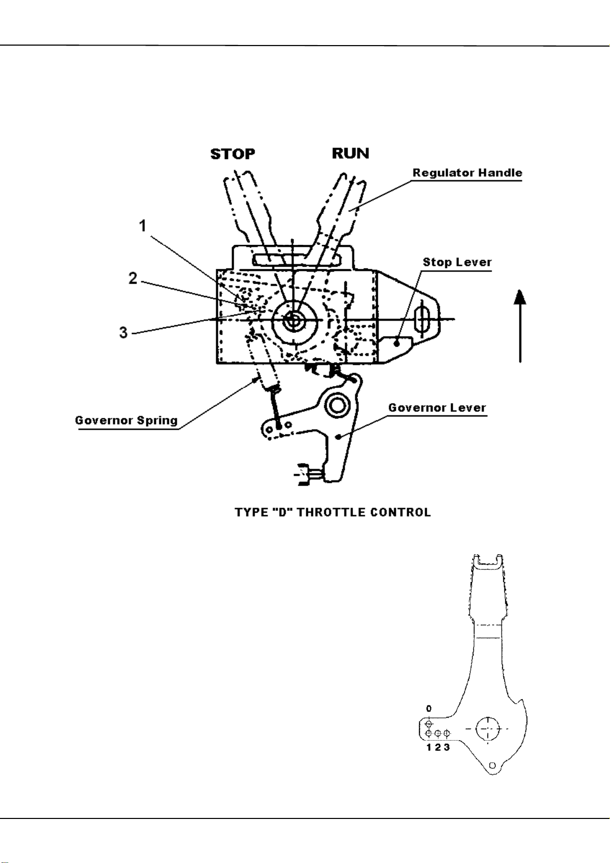
HANDFED MIXERS YANMAR L48 TYPE D THROTTLE
ENGINE THROTTLE CONTROL USED ON LATER
L48 ENGINES FITTED TO 100T, 150T, 175T & 200T
HANDFED MIXERS
NOTE: SOME GOVERNOR LEVERS MAY ONLY
HAVE TWO HOLES NOT THREE AS ILLUSTRATED
WITH THE REGULATOR HANDLE IN THE “STOP “ POSITION
REMOVE THE CENTRE SECURING BOLT AND THE
LOCKING SETSCREW FROM THE SLOT ADJACENT TO THE
STOP LEVER.
CAREFULLY LIFT THE THROTTLE CONTROL ASSEMBLY
AWAY FROM THE ENGINE SUFFICIENTLY TO GAIN
ACCESS TO THE GOVERNOR SPRING.
MOVE THE UPPER HOOK ON THE GOVERNOR SPRING
INTO THE No3 HOLE POSITION IN THE REGULATOR
HANDLE. (SEE DRAWING OPPOSITE ) LEAVE THE LOWER
HOOK IN THE SECOND INNER HOLE IN THE GOVERNOR
LEVER. REFIT THE THROTTLE CONTROL ASSEMBLY TO
THE ENGINE ENSURING THE SPRINGS DO NOT BECOME
DETACHED. ROTATE THE CONTROL ASSEMBLY IN THE
DIRECTION OF THE ARROW UNTIL THE LOCKING SCREW
IS AT THE BOTTOM OF THE SLOT BEFORE TIGHTENING UP
BOTH SCREWS. THE ENGINE SPEED SHOULD NOW BE
SET TO APPROX 2800RPM AND THE DRUM WILL ROTATE
AT APPROXIMATELY 22-23 RPM.

WORKSHOP MANUAL
100T / 150T / 175T
Winget Concrete Mixers
From 1988 Onwards
Issue 9 2015
Battery Removal/Replacement
The 12-volt battery is secured on the R/H side of the Yanmar engine within the
engine housing for security. To remove, unscrew the ‘T’ handle from the stop
control rod and remove the closing plate. (The Stop control rod is omitted on later
mixers) The battery is retained by a non-conductive clamping block, cover and
threaded studs, the studs pass through the clamp block screw down into and
through the engine mounting plate being retained below the plate with two M6
nuts. Remove the nuts, unscrew the studs and remove, lift off the cover and
clamp block, disconnect the battery leads and slide out the battery. Reverse the
procedure to refit the battery.
Drive Pulley/ “V” Belt Removal/Replacement
The “V” belt drive pulley is keyed onto the engine extension shaft and also held
by a small grubscrew through the pulley shank. An M8 setscrew and flat washer
is also screwed into the end of the engine extension shaft to retain the pulley.
Replacement requires the removal of the engine.
Unscrew the ‘T’ handle from the stop control rod where it passes through the
closing plate. (The Stop control rod is omitted on later mixers). Undo the knot in
the recoil rope retaining the handle where it passes through the side of the
engine housing, do not release the rope but remove the handle and pass the
rope back through into the housing. Tie a loose knot in the rope to prevent it
being pulled inside the recoil housing under spring tension. Alternatively the
recoil can be removed from the engine and allowed to hang inside the engine
housing. To remove the recoil mark its position on the flywheel housing and
remove the three small screws which retain the assembly in place.
Remove the engine housing closing plate, engine housing lid, top plate (175T)
and chain /belt guards. Disconnect the battery. Remove the ‘V’ belt and unbolt
the electrical panel from the side of the mainframe. Remove the bolts securing
the engine to the mounting plate and carefully lift the engine out of the housing.
Turn the engine through 180º’ to access the drive pulley and rest the engine back
on the mounting plate taking care it does not topple off.
Slacken the grubscrew and remove the setscrew and washer, pull off the pulley,
it may be necessary to use a small two legged puller if the pulley has been
attached for some time.
Coat the bore of the pulley and the extension shaft with anti-seize compound and
slide the pulley onto the shaft fully home up to the shoulder, fit the key,
grubscrew, setscrew and washer.

WORKSHOP MANUAL
100T / 150T / 175T
Winget Concrete Mixers
From 1988 Onwards
Issue 9 2015
Lift the engine back into the mainframe and secure to the bed. Insert the bolts but
do not fully tighten, refit the ‘V’ belt check the belt alignment, if the alignment is
incorrect rectify by sliding the engine mounting plate and bracket back and forth
on the engine bed, tighten the engine retaining bolts.
Check and adjust the belt tension by means of the long threaded adjusting
screws the tension is correct when the belt deflects approximately 8-12mm about
the centre line of the belt. The tension should be checked midway between the
two pulleys. When the tension is correct fully tighten all the bolts and recheck the
tension.
A belt running too tight will cause starting problems and the increased loadings
will increase the rate of wear on the belt causing it to stretch prematurely and
may also damage the crankshaft bearings. A belt running too slack will slip
under load with the result that the drum will cease to revolve.
Reconnect the battery and electric start panel, ensuring the wiring is secured and
will not chafe through.
Refit the recoil assembly or rope handle, engine housing lid, chain/belt guards
not forgetting the polythene plug, top plate, closing plate and where fitted the
stop control ‘T’ handle.
110/240 Volt 1PH Electric Motor
The motor runs at approximately 1420/1470 rpm and rotates Clockwise.
To accommodate the reduction in rpm at the motor and to prevent the
characteristics of chain drives damaging the motor, the countershaft chainwheel
and engine drive chain are replaced by a “V” belt and “V” drive pulley.
The motor is also mounted differently to the Lister Petter LT1/LV1 in that it is
bolted to a height adjustable bedplate, similar to the AC1-05, Yanmar and Honda
engines to allow for belt tensioning.
The contactor enclosure is attached to the chain/belt guard and a key lockable
‘emergency’ stop button is fitted to the exterior of the engine housing on the lefthand side.
Note, locking off the stop button prevents any un-authorised person from starting
the equipment BUT does not isolate the electricity supply. Before carrying out
any work on the motor, contactor or enclosure isolate the supply at the main
distribution board and attach a suitable ‘locked out’ tag to prevent the supply
being inadvertently re-connected.

WORKSHOP MANUAL
100T / 150T / 175T
Winget Concrete Mixers
From 1988 Onwards
Issue 9 2015
Refer to the wiring diagram for details of the connections between the motor,
contactor and emergency stop button.
Belt Drive Pulley/”V” Belt Removal/Replacement
The drive pulley is mounted onto the motor extension shaft, and is secured with a
feather key and grubscrew.
Unlike the diesel and petrol driven versions it is possible to remove the pulley
without removing the motor. To remove the pulley, first disconnect the electrical
supply and isolate the mixer. Remove the engine housing lid, closing and top
plates, upper and lower belt guard and “V” belt. When removing the upper belt
guard take care as the contactor is attached. Mark the position of the pulley on
the shaft. Turn the motor shaft until the grubscrew is visible, slacken the screw
and remove the pulley. Reverse the procedure to refit coating the bore of the
pulley with anti-seize compound prior to assembly.
Fit the “V” belt and confirm the alignment of the pulleys. Adjust the height of the
motor to tension the “V” belt. The tension is correct when the belt deflects 812mm check midway between the pulleys.
A belt running too tight may cause starting problems and the increased loadings
will increase the rate of wear on the belt causing it to stretch prematurely and
may also result in damage to the motor shaft bearings. A belt running too slack
will slip under load with the result that the drum will cease to revolve.
Refit the engine housing lid, closing and top plates and upper and lower belt
guards, not forgetting the plastic plug, take care not to damage the contactor
when refitting the upper belt guard. Reconnect the electrical supply.
Engine, Lister-Petter AC1-05 Electric Start, PTO Shaft Clockwise Rotation
A small number of 150T mixers, mainly two wheel fast tow are fitted with the
electric starting Lister-Petter AC1-05 engine. As with the Yanmar L40/L48 and
Honda engine there is no difference in build specification between “CE” marked
machines intended for use in the European Union or those intended for export
elsewhere. Unlike the Yanmar L40/L48 no back up starting system is provided in
the event that the electrical starting system fails, the AC1-05 powered mixers
where intended to be purely electric start.
For details on engine services or overhauls, changing engine oils, filters and
bleeding the fuel system refer to the engine operator’s handbook or engine
workshop manual.
Note: this ‘high speed’ engine is set to run at 1500 rpm and rotates clockwise at
the engine flywheel PTO.

WORKSHOP MANUAL
100T / 150T / 175T
Winget Concrete Mixers
From 1988 Onwards
Issue 9 2015
To provide the reduction in speed necessary to drive the drum at a nominal 22
rpm the countershaft chain wheel and engine drive chain are replaced by a “V”
belt and “V” drive pulleys.
The engine is also mounted on a height adjustable bedplate, similar to the
electric 110/240V motor, Yanmar L40/L48 and Honda GX160K1 to allow for belt
tensioning.
Power to charge the battery is provided by integral flywheel mounted charge
windings and engine mounted regulator with key switch control.
Battery Removal/Replacement
The 12-volt battery is secured below the engine bed between the rear wheels
enclosed by a removable cover to provide some security.
A simple clamp bar, two retaining rods and wing nuts retain the battery.
Remove the setscrews and nuts holding the cover, release the wing nuts and
remove the rods and clamp. Disconnect the battery leads and lift out the battery.
Reverse the procedure to refit the battery.
Drive Pulley/ “ V” Belt Removal/Replacement
The “V” belt drive pulley is combined with a short extension shaft and bolted
directly to the face of the engine flywheel, when selecting retaining bolts ensure
only the correct length of bolt is used to prevent the bolts passing straight
through the flywheel and damaging the charge windings. Replacement of the “V”
belt pulley/shaft requires the removal of the engine.
Remove the stop control rod where it passes through the closing plate.
Remove the engine housing closing plate, engine housing lid, chain /belt guards
and exhaust pipe. Remove the ‘V’ belt and unbolt the electrical panel from the
side of the mainframe, disconnect the battery. Remove the bolts securing the
engine to the mounting plate and carefully lift the engine out of the housing. Turn
the engine through 180º to access the drive pulley and rest the engine back on
the mounting plate taking care it does not topple off.
Remove the bolts and washers securing the pulley to the flywheel, as the pulley
sits in a small recess within the flywheel it may be necessary to tap the pulley
with a soft faced hammer in order to remove it, take care not to damage the
pulley in doing so.

WORKSHOP MANUAL
100T / 150T / 175T
Winget Concrete Mixers
From 1988 Onwards
Issue 9 2015
Reverse the procedure to refit taking care when selecting any replacement bolts
to avoid damaging the charge windings behind the flywheel.
Lift the engine back into the mainframe and secure to the bed. Insert the bolts but
do not fully tighten, refit the “V” belt check the belt alignment, if the alignment is
incorrect rectify by sliding the engine mounting plate and bracket back and forth
on the engine bed, tighten the engine retaining bolts.
Check and adjust the belt tension by means of the long threaded adjusting
screws the tension is correct when the belt deflects approximately 8-12mm about
the centre line of the belt. The tension should be checked midway between the
two pulleys. When the tension is correct fully tighten all the bolts and recheck the
tension.
A belt running too tight will cause starting problems and the increased loadings
will increase the rate of wear on the belt causing it to stretch prematurely and
may also damage the crankshaft bearings. A belt running too slack will slip
under load with the result that the drum will cease to revolve.
Reconnect the battery and electric start panel, ensuring the wiring is secured and
will not chafe through.
Refit the engine housing lid, chain/belt guards not forgetting the polythene plug,
closing plate and stop control rod.
Engine, Honda Petrol GX160K1 LX4 Recoil Start. PTO Shaft Anticlockwise Rotation.
There is no difference in build specification between “CE” marked machines
intended for use in the European Union or those intended for export elsewhere.
No starting handles are fitted to the Honda engines, instead a recoil rope starter
is fitted. The engine housing of Honda powered mixers differs in that the housing
incorporates large air inlet/outlets to provide the necessary cooling air and it is
important that in service these are not allowed to become blocked.
For details on engine services or overhauls, changing engine oils and filters etc
refer to the engine operator’s handbook or engine workshop manual.
Note: this ‘high speed’ engine is set to run at 2800 rpm and rotates anti-clockwise
at the half speed (1400rpm) 2:1 Reduction PTO shaft extension.
To prevent the characteristics of chain drives damaging the Honda engine which
lacks the heavy flywheel of the slow speed Lister-Petter LT1/LV1, the

WORKSHOP MANUAL
100T / 150T / 175T
Winget Concrete Mixers
From 1988 Onwards
Issue 9 2015
countershaft chain wheel and engine drive chain are replaced by a “V” belt and
“V” drive pulleys.
The engine is also mounted differently in that it is bolted to a height adjustable
bedplate, similar to the electric 240/110V motor, Petter AC1-05 and Yanmar
engines to allow for belt tensioning.
Drive Pulley/ “V” Belt Removal/Replacement
The “V” belt drive pulley is keyed onto the engine extension shaft and also held
by a small grubscrew through the pulley shank. An M8 setscrew, flat washer and
spacer are also fitted to the end of the engine extension shaft to retain the pulley.
Replacement of the pulley requires the removal of the engine.
Undo the knot in the recoil rope retaining the handle where it passes through the
side of the engine housing, do not release the rope but remove the handle and
pass the rope back through into the housing. Tie a loose knot in the rope to
prevent it being pulled inside the recoil housing under spring tension.
Alternatively the recoil can be removed from the engine and allowed to hang
inside the engine housing. To remove the recoil mark its position on the flywheel
housing and remove the small screws which retain the assembly in place.
Remove the engine housing closing plate, engine housing lid, top plate (175T)
and chain /belt guards and ‘V’ belt. Disconnect the exhaust pipe, remove the
bolts securing the engine to the mounting plate and carefully lift the engine out of
the housing. Turn the engine through 180º’ to access the drive pulley and rest the
engine back on the mounting plate taking care it does not topple off.
Slacken the grubscrew and remove the setscrew, washer and spacer, pull off the
pulley, it may be necessary to use a small two legged puller if the pulley has
been attached for some time.
Coat the bore of the pulley and the extension shaft with anti-seize compound and
slide the pulley onto the shaft fully home up to the shoulder, fit the key,
grubscrew, setscrew, washer and spacer.
Lift the engine back into the mainframe and secure to the bed. Insert the bolts but
do not fully tighten, refit the ‘V’ belt check the belt alignment, if the alignment is
incorrect rectify by sliding the engine mounting plate and bracket back and forth
on the engine bed, tighten the engine retaining bolts.
Check and adjust the belt tension by means of the long threaded adjusting
screws the tension is correct when the belt deflects approximately 8-12mm about
the centre line of the belt. The tension should be checked midway between the
 Loading...