

Page 1
Wine Zone Ductless Split System
Requires an HVAC technician to install and charge unit
Can be charged with R-22, NU-22B, MO99, or R-427A refrigerants
Electric connections for evaporator are hard wired to the condenser
Industrial grade for longer life
Indoor and outdoor condensing units available
Field supplied drain line, refrigerant, and electric connections required
WZDS9100 #2
1
Page 2

Supplies and Materials Needed for Installation
1. Condenser pad
2. Required electrical services
A. Dedicated service for condenser
B. 5-conductor low voltage wire from thermostat to condenser control panel
3. R-22, Nu-22B, MO99, or R-427A refrigerant for system
4. Miscellaneous hardware, brackets, sealant, reducers, etc…
5. An accurate digital probe style thermometer
6. Tools and equipment needed to perform the installation
7. Additional refrigerant line if line set exceeds 50 ft. in length. All of the 3/8” x 3/4” line set for line sets
81 to 200 equivalent feet.
Supplies and Materials Furnished with Equipment
1. Condenser with pre-wired control panel
2. Pre-assembled outdoor upgrade kit, if ordered
3. Wall mounted evaporator modified for system
4. Thermostat
5. 50 ft. of 3/8” x 5/8” line set
6. Filter drier, may be factory installed
7. Sight glass, may be factory installed
8. Fan cycle control, mounted and wired.
9. Wiring diagrams
10. Installation instructions with copy of Diagnostic Sheet
11. Warranty information with copy of Diagnostic Sheet
A qualified service technician must record all of the information on the diagnostic sheet before calling for
technical assistance. The technician must be able to identify the unit with the order number and serial numbers to
receive accurate trouble shooting assistance. All recommendations for repair or adjustment will be based on the
information provided by the service technician. Any incorrect recommendations based on incorrect or insufficient
data are not covered by the warranty.
WZDS9100 #2
2
Page 3

Installation Instructions
Caution: A qualified technician must install this refrigeration equipment. Please read, understand, and
follow all instructions in this manual prior to start up. Failure to install and adjust this refrigeration unit in
compliance with these instructions will void the warranty.
This unit is suitable for use with R-22 and Icor International’s NU-22B and other R-22 replacements such
as Arkema’s R-427A or DuPont’s R-438A (MO99). We suggest using NU-22B for the following reasons:
It is about 2% to 5% more efficient than R-22
ASHRAE Designated and safety classified A1: Nontoxic/Nonflammable
EPA Snap listed
Non-Ozone Depleting with Low Gl obal Wa rming Impact
Compatible with all standard refrigeration oils so no oil change is necessary
R-22 like properties over a broad range
Low discharge temperatures
Stocking distributors nationwide
The refrigerant oil in the unit must be replaced with a like volume of POE oil when using R-427A,
R-438A and other blended refrigerants. Multiple oil changes are not necessary.
A temperature pressure chart for R-22, NU-22B, R-427A and MO99 can be found on page 26.
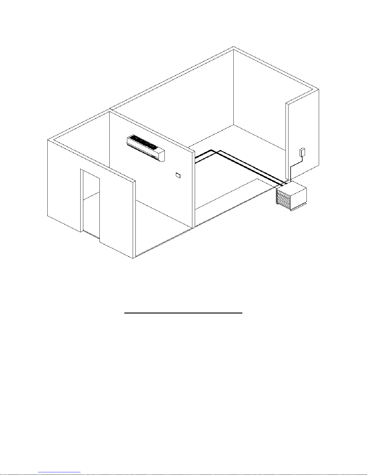
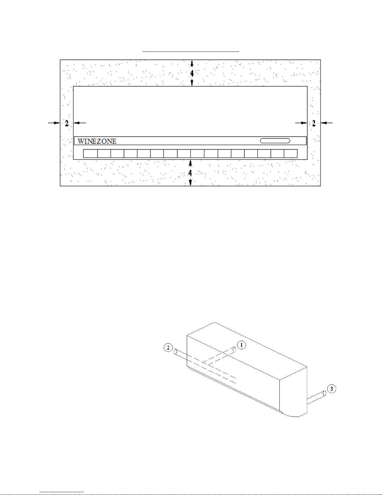
1. Select a suitable location for the evaporator with respect to air circulation, drain, refrigerant and electrical
lines. Adequate air circulation requires a 36” clearance in front of the unit, do not place any obstruction in
front of the evaporator. Do not attempt to duct this evaporator. Before installing any unit, the installer must
determine that the wall or ceiling can safely support the weight of the unit. Provide adequate clearance for
maintenance. Check local codes for additional precautions. The face of the evaporator should be within 4”
of the front of the racking, if placed in double deep racking you must bring the evaporator forward so it is
within 4” of the front of the rack.
2. Place the condenser at the desired location outside the wine cellar in a well-ventilated area or outdoors.
Indoor condensers must be placed in a space twice the volume of the wine cellar to prevent excessive
condensing temperatures. Check local codes for proper venting of mechanical rooms. Field supplied
vibration absorbing mounting pads and insulated compressor jackets effectively reduce noise transmitted
by the unit. Condenser face must be at least 12” from any obstruction and entering air must not exceed 110°
F. When installing an outdoor condenser, be sure that it is located so that leaves or snow do not accumulate
and block the airflow. This can be accomplished by setting the condenser on a concrete slab, blocks, etc.
Place the unit so prevailing winds do not blow rain, snow and debris into the open ends of the outdoor
cover. Avoid placing the outdoor condenser in direct sunlight, especially in warm climates. Condenser air
directed toward or away from the dwelling may cause undesirable noise for owners and their neighbors.
This must be considered when placing the unit outdoors.
3. Using a silver/phosphorus/copper alloy with between 5% and 15% silver, braze the refrigerant line set to
the evaporator and condenser with nitrogen flowing through the lines to eliminate carbon deposit build up
on the inside of the joints which could contaminate the refrigerant and restrict the drier and expansion
valve. To do this, open the system service ports. This will purge the nitrogen holding charge in the system.
Connect a nitrogen bottle to one valve and set pressure regulator to about 2 PSI. A small amount of
nitrogen will flow out the other valve.
You must install the line set according to Table 1 on the following page. Failure to do so voids the
warranty. The evaporator and/or condensing unit may have different fitting sizes than the line set, so field
supplied reducers are necessary. Run the line set according to Table 1, and reduce at the condenser and
evaporator connections.
WZDS9100 #2
3
Page 4
Maximum line length is 200 equivalent feet. Long sweep elbows and any bends in soft copper are
equivalent to 5 linear feet. Line lengths in excess of 200 equivalent feet may cause compressor damage and
will void the warranty. Example: To determine the equivalent length of the line set add up the linear feet of
suction line. Multiply the number of elbows required and add it to the total length of suction line.
Example:
Horizontal pipe 40 linear ft.
Vertical pipe 10 linear feet
8 elbows x 5 40 equivalent feet
Total equivalent feet 90 equivalent feet
Following Table 1 and guidelines for vertical risers below, the correct line set size is 3/8” liquid line and
3/4” suction line. The 10 linear feet of vertical suction line is 5/8”
Proper piping practices must be followed. The line set must be securely fastened to the building structure
for its entire length. The suction line must be insulated the entire length of the run. Horizontal line runs
must slope 1/2” per 10’ towards the condenser for proper oil return. No dips, sags or other low spots that
will trap refrigerant oil are permitted. This prevents starving and slugging the compressor with oil. We
highly recommend using rigid copper for this reason.
For systems with condensers 10 feet or more above the evaporator, reduce the suction line size by one. For
example, 5/8” line changes to 1/2” and 7/8” changes to 3/4” for the vertical section of the line only. Install
a P trap at the bottom of the riser of the same size as the horizontal piping.
Line sets up to 80 equivalent feet will use 3/8” liquid line and 5/8” suction line.
Line sets 81 to 200 equivalent feet will use 3/8” liquid line and 3/4” suction line.
Line sets longer than 200 equivalent feet will void the warranty. Minimum line set length is 15 linear
feet.
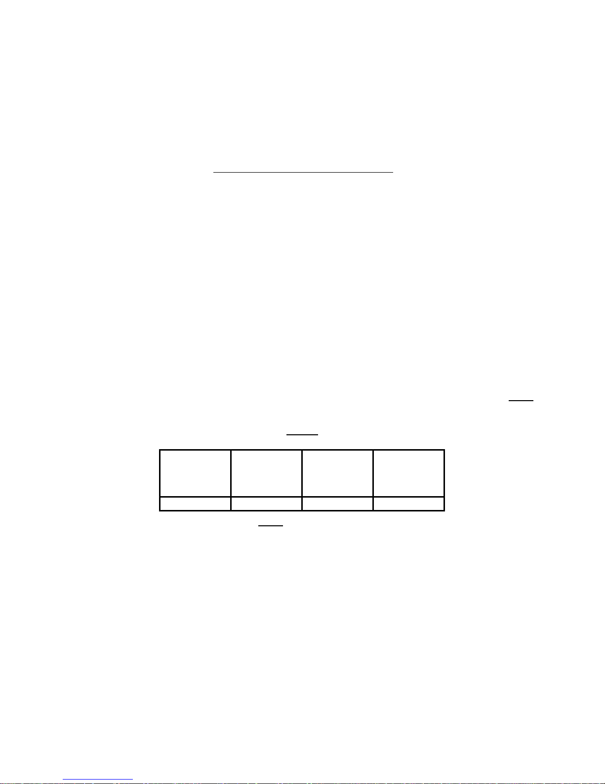
Table 1
Line set sizes may differ from system component fitting sizes so field supplied reducers are necessary. Run
the line set according to Table 1, and reduce at the condenser or evaporator if necessary.
Unit
WZDS9100
Minimum linear line set length is 15’
Liquid Line
Equivalent Feet
3/8 5/8 3/4
Vapor Line
Up to 80
Vapor Line
81 to 200
Equivalent Feet
For outdoor units, cut or drill a hole through the most convenient stationary side of the condenser cover large
enough for the line set to easily pass through. Cut the hole above the height of the compressor. Do not run
the line set through the bottom of the unit or the air grilles at either end. Do not run the line set through a
panel that moves when the lid is opened.
WZDS9100 #2
4
Page 5
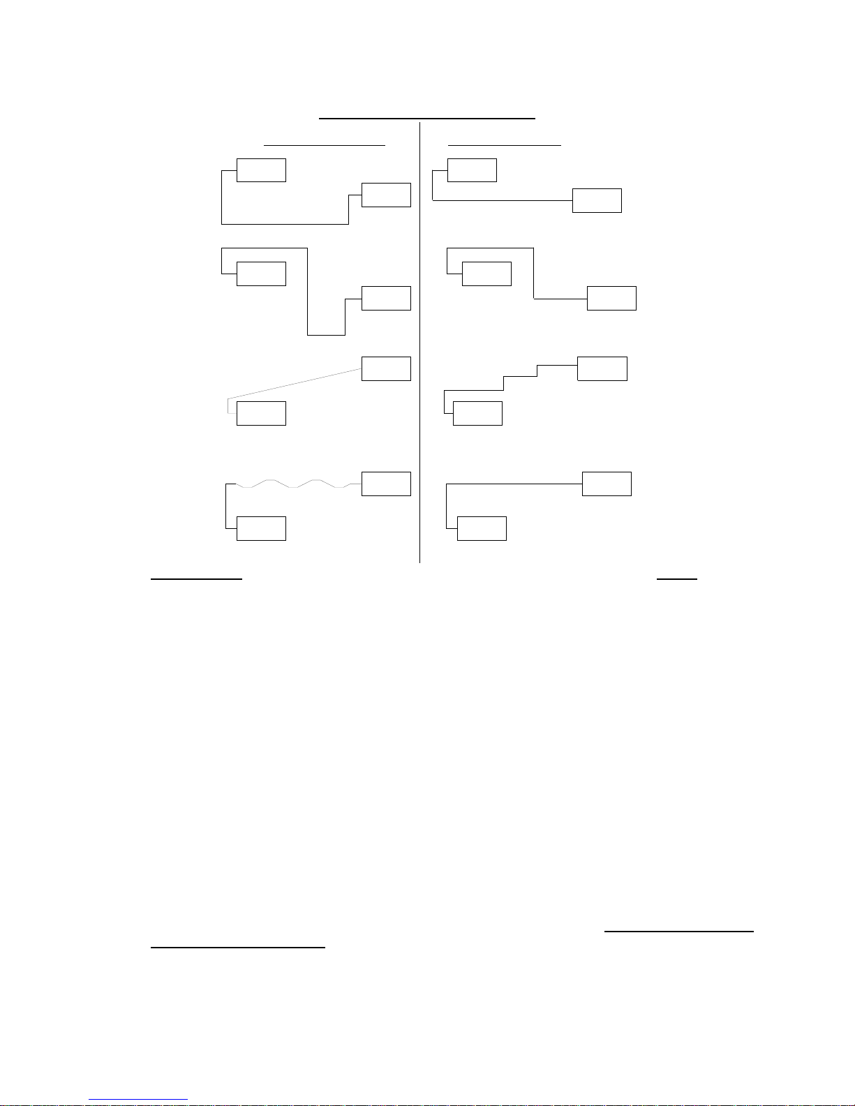
Sample Piping Configurations
Inc o rre c t In sta lla tion
Evaporator
Condenser
Cre a te s a n o il tra p
Evaporator Evaporator
Condenser
Cre a tes an o il tra p
Oil runs away
from C on de nser.
Evaporator Evaporator
Soft copper sags
and creates an oil trap.
Evaporator Evaporator
Condenser Condenser
C or re ct I n sta llatio n
Evaporator
Condenser
Condenser
CondenserCondenser
Rule of thumb: Once the suction line leaves the evaporator and turns downward, it cannot turn and
go back up to get to the condenser. The only time a trap in the suction line is acceptable is at the
bottom of a 10’ or taller riser.
4. Install the filter dryer and sight glass, if not already factory installed. Wrap with a wet rag to prevent over
heating during brazing.
5. Perform leak test with dry nitrogen, but never expose the system to leak test pressures greater than 150
PSI. Test all fittings including factory installed flare fittings on condenser and evaporator that may
have loosened during shipping. Leaks on unit(s) from a result of loose valves, interconnecting fittings,
and/or field piping are not covered by the warranty. It is the installer’s responsibility to locate and repair
all leaks prior to start up.
6. Evacuate the system to 1000 microns for 1 hour.
7. Install electrical wiring according to the Electrical Requirements on page 14 and the appropriate wiring
diagram. Follow all applicable codes.
8. After isolating the vacuum pump from the system, break the vacuum to a positive pr essure using refrigerant
connected to the liquid line. Add approximately 20 psi of refrigerant vapor. Do not start unit for the
first time with a full charge. Adding more refrigerant prior to start up will damage the compressor.
Always charge NU-22B and other blended refrigerants in liquid state.
WZDS9100 #2
5
Page 6

9. Apply power to units for 24 hours prior to start up to allow crankcase heater to warm the
compressor and then start the unit. Complete the charging process with the compressor running and add
the balance of the charge into the suction line of the system. Liquid refrigerant should never enter the
compressor directly. Use a metering device to prevent slugging when charging with liquid.
10. The ICM333 Head Pressure Control is factory set to maintain approximately 225 psi head pressure. Verify
the head pressure remains at 225 psi or above. See page 22 and the charging table on page 23 for
instructions on how to adjust the fan speed controller. Never adjust the pressure control to bring on the
condenser fan motor above 250 psi. Slowly add refrigerant until the bubbles in the sight glass d isappear.
The condenser fan motor must be running to complete the charge
11. For R-22: After the system has run for 10 minutes check the sight glass again. During normal operation
with R-22 there should be no bubbles in the sight glass. If bubbles are present, the system is low on
refrigerant. Add refrigerant to eliminate the bubbles. Charge the system to approximately 5 of sub-
cooling. To calculate sub-cooling for R-22 subtract the liquid line temperature from the saturation
temperature corresponding to the head pressure. Measure the liquid line temperature between the receiver
and filter drier with and an accurate, digital, thermocouple style thermometer.
For Nu22B or other blended refrigerants: Some bubbles may be present with a full charge of a blended
refrigerant. Charge the system to approximately 5 of sub-cooling. To determine sub-cooling for NU-22B
or other blended refrigerants, subtract the liquid line temperature from the bubble temperature
corresponding to the head pressure. Measure the liquid line temperature between the receiver and filter
drier with an accurate, digital, thermocouple style thermometer.
12. Allow the wine room temperature to fall to 55F. Check the super heat at the evaporator. Measure the
suction pressure at compressor access port. From refrigerant pressure-temperature tables, determine the
saturation temperature (for R-22) or the dew temperature for NU-22B or other blended refrigerant at the
observed suction pressure. Measure the suction line temperature at the compressor. Subtract the saturation
temperature (Dew temperature for blended refrigerants) from the measured suction line temperature. The
difference is the superheat. Refer to the temperature pressure chart on page 26 in these instructions.
The superheat should be 8 to 16F. If the superheat is not in this range, the thermostatic expansion valve
must be adjusted. To adjust the expansion valve, remove the seal cap from the bottom of the valve. Turn
the adjustment screw clockwise to increase superheat and counterclockwise to decrease superheat.
Caution: There are 10 turns on the adjustment stem. When stop is reached while turning the
superheat adjustment stem, any further turning will damage the valve. One complete 360 turn
changes the superheat approximately 3-4F. As much as 30 minutes may be required for the system to
stabilize after the adjustment is made. Replace and hand tighten the seal cap. Always replace the
evaporator face plate between TXV adjustments.
13. Perform the final check of the refrigeration unit. The cellar temperature must be between 53 and 58 F.
Check the sight glass and gauge readings again. The super heat must be 8-16 F (see step 12). The hot gas
line temperature must not exceed 260 F. Never exceed the maximum amp draw (RLA) for the
compressor. Adjust the TXV, and charge as necessary. All measurements should be taken with the
condenser fan motor running. All temperature readings should be taken with a digital probe style
thermometer.
14. If the recommended system pressures and temperatures cannot be achieved, refer to the troubleshooting
chart on pages 24 and 25.
15. Clearly mark the unit to identify the refrigerant used.
WZDS9100 #2
6
Page 7
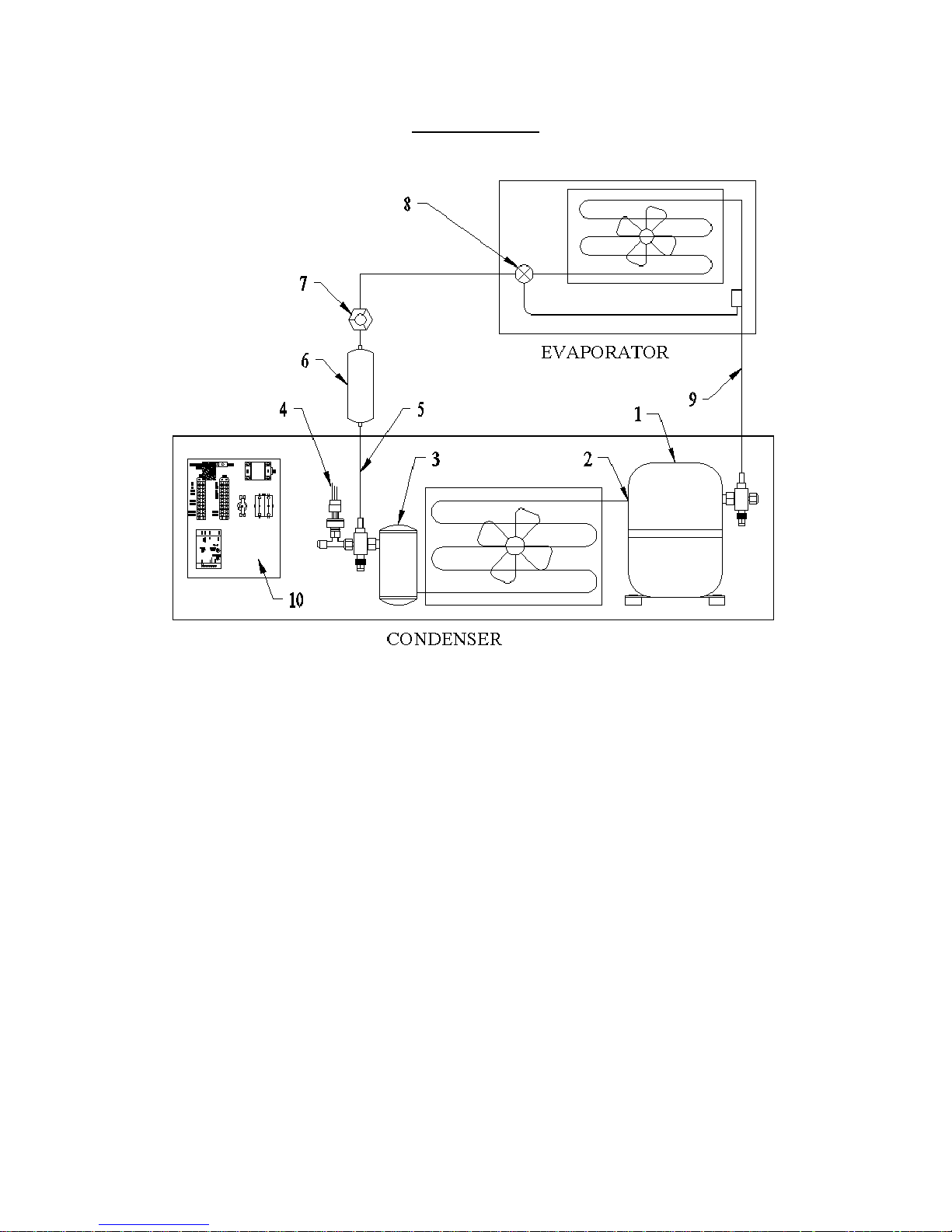
Piping Diagram
1. Compressor.
2. Discharge (hot gas) line. The vapor line between the compressor outlet and the condenser coil inlet.
Measure the discharge (hot gas) line temperature here, approximately 12” from the compressor outlet. This
temperature should never exceed 260 degrees.
3. Receiver. Measure the head pressure at the receiver service valve.
4. ICM333 Head Pressure Control. See step #10 on page 6.
5. Liquid line. Measure the liquid line temperature here to determine sub-cooling.
6. Filter drier.
7. Sight glass.
8. Thermostatic expansion valve. See step 12 on page 6.
9. Suction line. Measure the suction pressure at the compressor suction service valve. Measure the suction
line temperature near the compressor service valve. See step 12 on page 6.
10. Condenser control panel. Contains the system electrical components.
WZDS9100 #2
7
Page 8
Installation of the Indoor Unit
Firmly secure the evaporator mounting plate on a wall strong enough to withstand the weight of the unit. The plate
must be level and allow for the clearances shown in the figure above. The evaporator must be installed in such a way
as to prevent short cycling of the discharge air with the return air. Adequate air circulation requires a 36”
clearance in front of the unit; do not place any obstruction in front of the evaporator. The face of the
evaporator should be within 4” of the front of the racking, if placed in double deep racking you must bring the
evaporator forward so it is within 4” of the front of the rack. Do not place the unit in direct sunlight, or above a door
or window. Do not attempt to duct this evapor ator. The location must also be suitable for refrigerant piping and
condensate drainage. The evaporator discharge air must not blow on the thermostat.
The refrigerant piping can be routed to the unit in a number of ways. Number 2 in the diagram below indicates a
cutout in the unit casing. Using the cutout will leave the refrigerant piping, condensate d rain, and electric exposed
in the cellar and should be avoided. Numbers 1 and 3 indicated below, are fo r piping routes that will leave the
refrigerant lines, drain and electric concealed, and should be used for the most attractive installation. A single, 2¼”
or 2 ½” hole will accommodate the passage of the line set, drain and electric through the wall. Slope the hole
downward through the wall and fasten the drain line to the bottom of the line set for proper drainage. These hole
locations are indicated on the mounting plate drawings as well. The refrigerant piping may be gently bent or twisted
to use any of the indicated pipe routes.
When the line set will be run on the inside
of the wall before the drywall is hung, use
the suggested route (route number 1).
Route number 1 is the preferred route.
Route 2 will leave the refrigerant piping,
electric, and drain exposed. For installations
where the line set will be accessible on the
backside of the wall, the alternate route
(route 3) can be used. Use caution when
using route 3. Secure the piping above the
bend before turning the piping to use
route 3 to prevent kinking the suction
line.
WZDS9100 #2
8
Page 9
WATER
LEAKING
WATER
LEAKING
WATER
LEAKING
END DIPPED
INTO WATER
DRAIN
CORRECT
WRONG
WRONG
WRONG
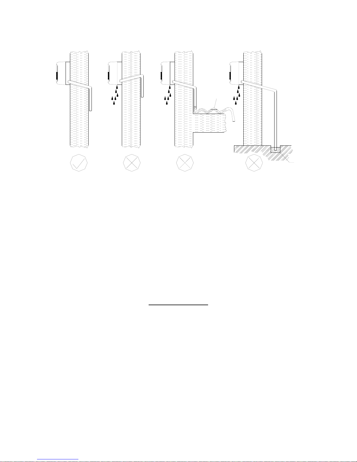
The indoor drainpipe must slope downward and have no traps. The drain must be fastened to the bottom of the
refrigerant lines. The drain requires an air gap to flow properly. Place the two hooks at the rear top of the
evaporator to hang the unit from the upper edge of the mounting plate. Ensure the hooks are properly seated on the
mounting plate by sliding the unit to the left and right. Gently press on the bottom face of the evaporator to snap the
bottom of the evaporator into place on the mounting plate.
The face of the evaporator casing can easily be removed. Screws are concealed under plastic covers on the bottom
leading edge of the unit, under the air discharge louver . Remove the covers to expose the screw heads an d remove
the screws. Remove screws above the air discharge under the hinged filter cover. Pull out and lift the botto m of the
evaporator casing to uncover the electric hook up.
After installation, properly seal the hole(s) where the refrigerant, drain and electric lines penetrate the wall
or ceiling. Failure to do so may result in uncontrolled condensation and water damage.
Evaporator Electric
Securely fasten the ground wire to the terminal with the green or green and yellow striped wire. The other two wires
on the evaporator terminal block receive 230 volts from terminals marked EVAP on TB1 in the condenser control
panel.
WZDS9100 #2
9
Page 10
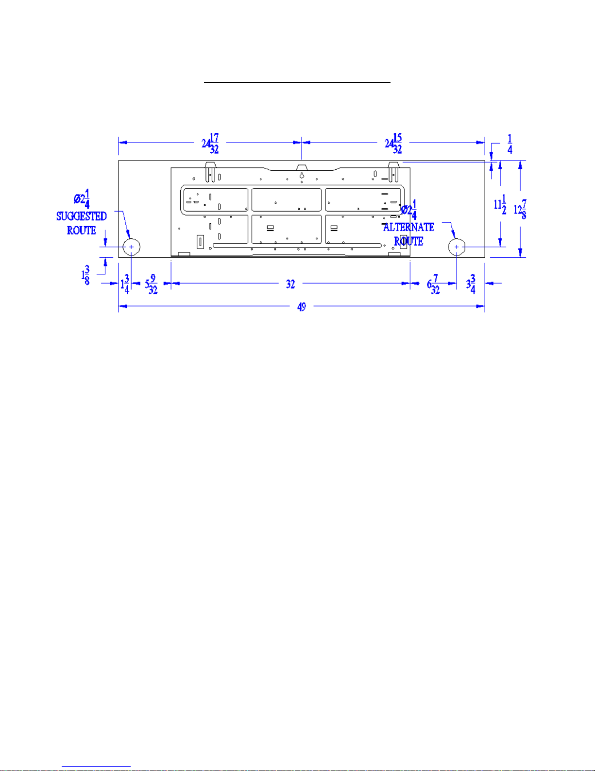
Mounting Plate for 9100 Evaporators
The holes shown are the best locations to route the refrigerant lines, condensate drain, an d electric. For installations
where the line set will be accessible on the backside of the wall, use the alternate route. When that is not possible,
and the line set will be run inside the wall before the drywall is installed, use the suggested route. This will leave the
flare connections exposed so they can be connected after the walls are finished.
Use caution when using the alternate route. Secure the piping above the bend before turning the piping to
prevent kinking the suction line.
A qualified service technician must record all of the information on the diagnostic sheet before calling for
technical assistance. The technician must be able to identify the unit with the order number and serial numbers to
receive accurate trouble shooting assistance. All recommendations for repair or adjustment will be based on the
information provided by the service technician. Any incorrect recommendations based on incorrect or insufficient
data are not covered by the warranty.
WZDS9100 #2
10
Page 11
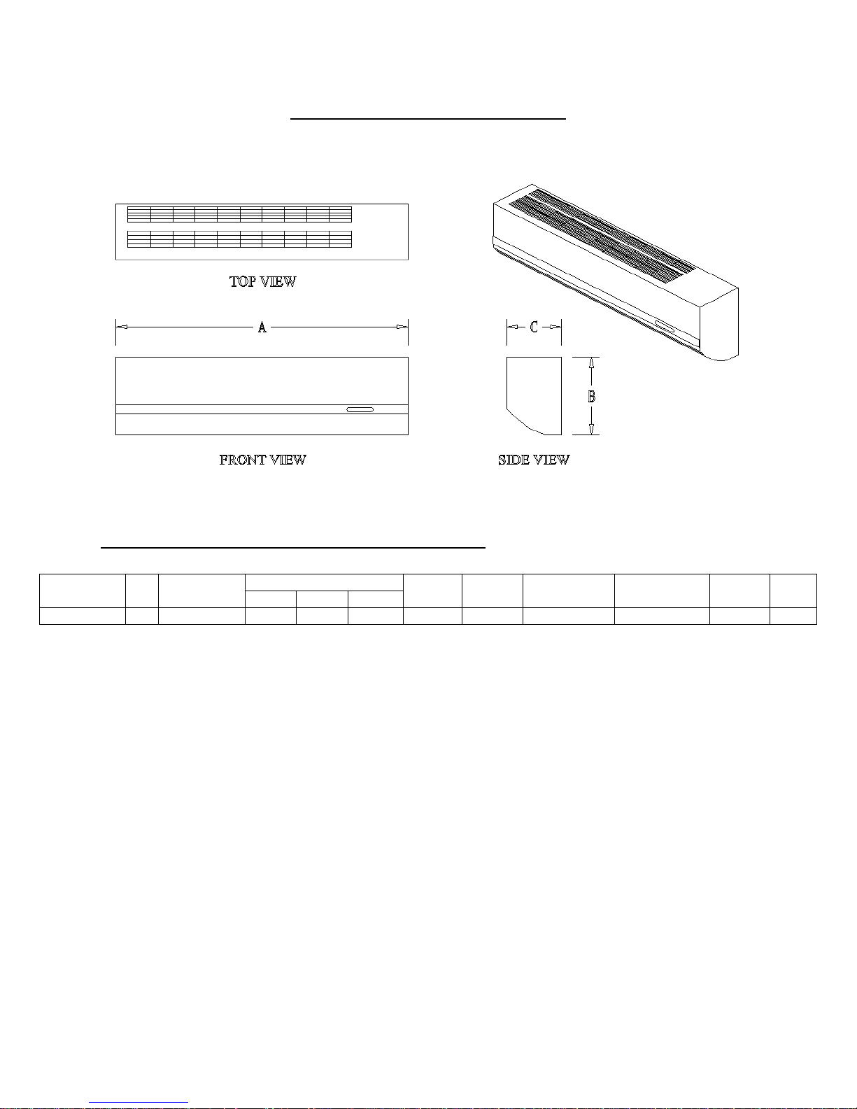
Ductless Split Wall Mount Evaporator
Specifications for Standard Ductless Split Evaporator
System dB Evaporator
WZDS9100
45 WB036 49 12 7/8 9 1/8 3/8 MF 5/8MF 5/8 Barbed 208-240/60/1 37 lbs. 15
You must install a line set according to Table 1 on page 4.
Field supplied reducers may be required. Reduce at the evaporator and condenser connections.
A minimum of 4” clearance required on top and bottom, 2” of clearance required on each side.
Dimensions In Inches
A B C
Liquid
Fitting
Suction
Fitting
Drain
Fitting
Power
Supply
Weight
Max.
Fuse
WZDS9100 #2
11
Page 12

Condenser Specifications
Outdoor Condenser
You must install a line set according to Table 1.
Field supplied reducers may be required. Reduce at the
evaporator and condenser connections.
Minimum of 12” clearance required on each side of unit.
Minimum of 36” clearance required above unit.
Model dB
WZDS9100/OC
Model dB
WZDS9100/IC
WZDS9100 #2
Length
In
inches
58 27 24.5 22 3/8 SW 5/8 SW 170 208-230/60/1 11.0 15
Width
in
inches
Height
in
inches
Liquid
Line
Fitting
Suction
Line
Fitting
Wt.
In
lbs Power Supply
Min
Circuit
Amps
Max
Fuse
Indoor Condenser
You must install a line set according to Table 1.
Field supplied reducers may be required. Reduce at the
evaporator and condenser connections.
Minimum of 12” clearance required on each side of unit.
Length
In
inches
58 28 24.5 20.25 3/8 SW 5/8 SW 139 208-230/ 60/1 11.0 15
Width
in
inches
Height
in
inches
Liquid
Line
Fitting
Suction
Line
Fitting
Wt.
In
lbs Power Supply
Min
Circuit
Amps
Max
Fuse
12
Page 13

Field Wiring
Condensing unit Control Panel
Terminal Board One
Terminal L1 – *230 Line voltage for the condenser (See condenser specifications for proper fuse size)
Terminal L2 – *230 Line voltage for the condenser (See condenser specifications for proper fuse size)
Terminal EVAP – Load voltage to the evaporator fan motor. Connect to terminal block in the
evaporator
Terminal Board Two
Terminal R – Thermostat R
Terminal Y – Thermostat Y
Terminal C – Thermostat C
Terminal G – Thermostat G.
Terminal A – Thermostat A, used only with humidification
Terminal HUM – 24 volt humidifier
System Ground Lug Above Terminal Boards
Electrical Requirements
1. Check the Copeland rating plate located on top of the condenser coil, for proper voltage, maximum fuse,
run load amperage, and wire size.
2. Line voltage from service panel for cooling unit. The power circuit connects to terminals L1 and L2 on
TB1 in the condenser control panel.
3. The evaporator circuit connects to terminals marked EVAP on TB1 in the condenser control panel.
4. Low voltage wire from the thermostat goes to the condenser control panel only. No low voltage
connections are required at the evaporator. Low voltage control wiring runs from the thermostat to the
condenser control panel.
5. All equipment must be installed according to the National Electric code and all local codes and ordinances.
WZDS9100 #2
13
Page 14

Line Voltage
1. Run a 230-volt circuit from the service panel to terminals L1 and L2 on TB1 in the condenser control
panel. Check the Copeland rating plate or page 12 for the proper fuse size. Attach the ground wire to the
lug in the upper left hand corner of the condenser control panel.
2. Load voltage for the ductless evaporator will come from terminals marked EVAP on TB1 in the condenser
control panel. Connect these wires to the small terminal block with the evaporator fan motor wires
attached. Attach the ground wire to the terminal with the green or green and yellow striped wire.
3. Each unit must be installed in accordance with the National Electric code. Check local codes for additional
precautions and ordinances to installation.
WZDS9100 #2
14
Page 15
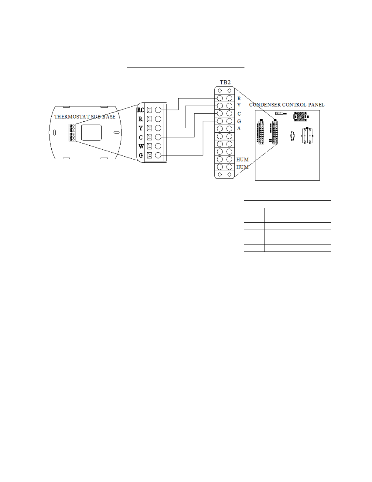
Thermostat Installation Cooling Only
Mount the Honeywell FocusPRO5000 thermostat in the cellar approximately 5
feet above the floor in an area of good air circulation of average cellar
temperature. Do not install it where it will be affected by the evaporator supply
air, lighting, wall switches, concealed pipes or chimneys, or warm exterior
walls, etc. The thermostat terminal RC connects to terminal R on TB2 in the
condenser control panel. Thermostat terminal Y connects to terminal Y on TB2
in the condenser control panel. Thermostat terminal C connects to terminal C
on TB2 in the condenser control panel. Thermostat terminal G connects to
terminal G on TB2 in the condenser control panel. Use quality 18-gauge thermostat wire. Read and follow the
manufacturer’s installation instructions.
We recommend you enter the Installer Setup in the Honeywell Installation Guide and choose the followin g settings
#1 System type to 4 for Cool only
#9 Stage 1 compressor cycle rate to 3
#14 Temperature display to 0 for Fahrenheit
#15 Compressor protection to 5
#28 Cool temperature range stop to 53
Turn the system to cool and set the temperature to 55.
Conventional Terminal Letters
24 VAC power
RC
Cooling
Y
24 VAC common
C
Not used
W
Fan
G
Not used
A
WZDS9100 #2
15
Page 16

Thermostat Installation for Cooling and Humidification
Thermostat Installation
Mount the WineZone thermostat in the cellar approximately 5 feet above the floor in an area of good air circulation
of average cellar temperature. Do not install it where it will be affected by the evaporator supply air, lighting, wall
switches, concealed pipes or chimneys, or warm exterior walls, sunlight, etc. Use quality 18-gauge thermostat wire.
Read and follow the manufacturer’s installation instructions. Carefully read and understand the instructions
supplied with the thermostat before attempting to operate or install this thermostat. The following thermostat
installation instructions are a summary of the install and set up for using this thermostat with a WineZone system.
For detailed installation and troubleshooting instructions please refer to the manufacturer’s instructions included
with the thermostat.
Install the Wallplate
1. Position the wallplate on the wall with the directional arrow pointing up and the terminal blocks facing
outward.
2. Pull equipment wires through the wallplate wiring passage.
3. Use a level to determine the best horizontal wallplate mounting position.
4. Mark positions of screw holes (two at minimum) with a pencil and remove wallplate.
5. Drill holes at pencil-marked locations (3/16” for drywall, 7/32” for plaster).
6. Insert the wall anchors in the holes, tapping them into place.
7. Mount the wallplate onto the wall and insert screws through the mounting holes. Assure that all loose
wires come through the center opening of the wallplate.
8. Cap off any unused wire and terminate properly according to local building codes.
WZDS9100 #2
16
Page 17

Attach Wires to Thermostat Wall plate
1. Select the terminal designations that correspond to the system type. Follow the table below:
Warning: Disconnect power before beginning installation.
Caution: Copper wire only. Insulate or wire-nut all unused
leads.
Use care to avoid electrostatic discharge to thermostat.
Note 1: Do not connect wire to A if a humidifier is not installed.
Note 2: Do not connect wire to Y2 or W1 if a duct heater is not
installed.
2. Using a small flathead screwdriver, loosen the screws on the terminal
blocks that correspond to the system type.
3. Strip the insulation of each wire at a proper length (about 1/4”)
Conventional Terminal Letters
Unswitched side, 24 VAC
C
Not used
W1
Not used
W2
Fan
G
Humidity
A
Not used
E
Stage 1 Cool
Y1
Not used
Y2
Power for Heating
RH
Switched Side, 24 VAC
Power for Cooling,
RC
Switched Side 24 VAC
Sensor Common, if used
SC
Not used
S1
Not used
S2
Not used
S3
4. On the wallplate, insert wires into the terminal blocks that correspond to the system type, then re-tighten
each screw for each terminal.
Note: Do not over-tighten or use excessive force.
5. Assure that no uninsulated wires are exposed: Cap off and place a wire nut on any unused wires. Assure
that the attached wires fit into the cavity on the back of the thermostat.
Connect Power to the Thermostat Wallplate
Power Options
The T12000 Series thermostat will operate on 24 VAC power and/or two AA batteries (both are recommended).
Using 24 VAC with AA battery backup is highly recommended.
Wiring 24 VAC Common
Single-Transformer system. Connect the common side of the transformer to the “C” screw terminal of the
thermostat wallplate. Assure that the metal jumper connects “RC” and “RH.” Connect power side to the RC/RH
and assure that the jumper remains in place
Install Batteries and Remove Tab
1. Insert two AA batteries (included) into the back compartment of the thermostat.
2. Remove the plastic insulator tab from the back side of the thermostat. IMPORTANT: The insulator tab
must be removed before setting the real-time clock.
Set the Clock, Month, Day
When power is first applied to the thermostat, it will activate the clock display. It is recommended that the time and
day are entered before performing advanced configuration. On the touchscreen area, press the Clock key and use
the up and down arrows to set the hour mode, clock hour, minutes, year, month, and numerical date. Press Done to
finish.
WZDS9100 #2
17
Page 18

Verify System Setting is Turned Off
1. Press any part of the touchscreen area to enter the Home Display.
2. Press System to enter system mode
3. Press System repeatedly until “Off” flashes, then press Done.
4. Press Fan key to enter fan mode.
5. Press Fan repeatedly until “Auto” flashes, then press Done.
Perform Advanced Configuration
Perform advanced configuration before attaching the thermostat to the wallplate. Advanced configuration is done
by simultaneously pressing the lower left and lower right touchscreen area for about 5 seconds, which gives user
access to Service Menus. Use the following table to set each desired Service Menu item. Advanced configuration
allows the user to configure the thermostat to match the system type and to customize several thermostat settings.
System type for WineZone systems is 1 Stage Cool/1 Sta ge Electric Heat. Changed value s are automatically
retained. Press Done only if you wish to exit Advanced Configuration. Service menu availability is dependent upon
system type and upon system configuration.
Menu Feature Options Default Recommended Setting
100 Schedule Format 0-3 1 0= Nonprogrammable
101 Daylight Saving Time 0,1 0 1= Enabled (2007 U.S. Format)
110 System Type 1-13 1 1= 1 Heat/1 Cool conventional
120 Fan Control (heating) 0,1 0
1= Electric furnace (thermostat controls heating
fan)
150 Backlight 0,1 0 0= Backlight temporarily on
170 Remote Sensor 0-5 0
0= No sensor
1= Indoor sensor (if used)
180 Heat Pump Compressor Lockout 0-45 0 0= No sensor
190 Heat Pump Auxiliary Lockout 0-60 0 0= None
230 Furnace Filter Change Reminder
0; 30; 60; 90;
120; 365
0
0= Off
240 Number of Program Periods 2; 4 4 4= 4 Events per day
250 Clock Format 12 or 24 12 12= 12-hour clock mode
260
Temperature Format
F or C
0,1 1
1= Fahrenheit
270 Fan Off Delay Heat 0-99 0 20= 20 Seconds
280 Fan Off Delay Cool 0-99 0 20= 20 Seconds
290 Range Low 50-90 50 50, Choose the lowest selectable setpoint
300 Range High 50-90 90 68, choose the highest selectable setpoint
310 Setback Low Off, 50-82 55 0= Off
320 Setback High Off, 58-90 90 0= Off
330 Zone Temp Offset +/-9 0 0= No offset
340 Keypad Lockout 0-3 0 0= No Key pad lockout
341 Enable Pin Access 0,1 0 0= Disable
350 Fan Mode Enable 1-3 3 3= On or Auto: allows user to select
360 System Mode Enable 0-3 1 1= Off, Heat, Cool. Auto
370 Economizer/Outside Air Damper 0-4 0 0= Off
3= Selects change over deadband value between
380 Minimum Deadband Adjustment 3-10 3
heating and cooling modes to prevent short
cycling
390 Pre-Occupancy Purge 0-3 0
WZDS9100 #2
18
0= Select to energize fan for selected number of
hours (0-3) prior to all occupied events.
Page 19

395 Maximum Override Time Limit 0, 1-4 3 3= 3 Hours
400 Cycles Per Hour Cooling Stage 1 0-6 3
420 Cycles Per Hour Heating Stage 1 0-12 5
460 Heat Recovery Rate 0-18 5 0= Disable ramp recovery
470 Cool Recovery Rate 0-18 5 0= Disable ramp recovery
480 Minimum Off Time 1-10 4
490 Humidity Control Enable * 0-3 2
491 Humidity Deadband 10-50 10
500 Programmable/Intermittent Fan 0-2 0 0= Disable
510 Power Harvesting 0-3 0 0= No power harvesting available
520 Default Display Icons 0-4 0 0= Time, Temp, SP
530 Revision - - Not Adjustable
540 Factory Default Reset 0,1 0 0=Disable
600 System Test Main Output (Cool) 0-2 0 0= Disable
610 System Test Main Output (Heat) 0-3 0 0= Disable
620 System Test Fan Output 0,1 0 0= Disable
630 System Test Emergency Output 0,1 0 0= Disable emergency output
640 System Test Economizer 0,1 0 0= Disable economizer output
*IMPORTANT! Some humidity control must be selected to view the humidity on the thermostat. If
no humidity options are installed, DO NOT connect wires to terminals A or Y2. Only connect wire to
A if a humidifier is installed. Do not connect wire to Y2.
3= Defines number of cycles per hour for
cooling
5= Defines number of cycles per hour for
heating
4= 4 Minutes off time for both heat and cool
output
Selects how humidity will be controlled. When
dehumidify is enabled the Y2 terminal becomes
dehumidify. Note: If option 3 is selected,
Service Menu 491 becomes available.
0= Disable (Humidity not displayed on
touchscreen).
1= Dehumidify
2= Humidify
3= Dehumidify and Humidify
10= 10% RH deadband between humidi fy and
dehumidify
Mount the T12000 Onto the Wallplate
1. Position the thermostat slightly above the mounted wallplate, then secure the hooks on the backside of the
thermostat to hinge pockets on the wallplate. Note: The top of the thermostat should slip into the hinge
pockets easily. Do not use excessive force.
2. Align the pins on the back side of the thermostat with the terminal blocks on the wallplate.
3. Gently bring down the thermostat onto the wallplate so the pins on the back of the thermostat fit into the
terminal blocks on the wallplate.
WZDS9100 #2
19
Page 20

Verify Thermostat Operation
Press the desired button until the preferred selection blinks. Press Done to select and save the selection.
1. Set the system to Off. Nothing should operate, including the Fan.
2. Set the fan to Auto
3. Set the system to On. Press the up and down arrows to adjust the temperature. Adjust the temperature
setpoint above the cellar temperature displayed on the touchscreen.
4. Set the Fan to On. The indoor fan should come on.
5. Set the Fan to Auto. The indoor fan should go off.
6. Adjust the temperature setpoint below the cellar temperature displayed on the touchscreen. The condenser
and indoor fan should come on.
7. If a humidifier is installed, adjust the Humidity setpoint above the humidity displayed on the touchscreen.
The humidifier should come on. Set the humidity setpoint below the humidity displayed on the
touchscreen. The humidifier should go off.
8. Adjust the temperature setpoint above the cellar temperature displayed on the touchscreen. The condenser
and indoor fan should go off. Nothing should be running.
9. Set the Humidity setpoint above the humidity displayed on the touchscreen. The humidifier should come
on.
10. Set the temperature to 55 and the Humidity to 65%.
Humidifier Installation
Install the Wine Guardian® Freestanding Humidifi er. Ru n
the humidifier prior to installation as the warranty does not
cover removal of the unit. Please read and understand the
owner’s manual and installation instructions prior to start
up. Follow the manufacturer’s manual to locate and mount
the free-standing humidifier. Install the hot water line and
drain according to the manufacturer’s instructions.
Disregard wiring instructions that include humidistat
wiring. The Wine Guardian® humidistat and transformer
are not necessary when used with the WineZone thermostat.
Cut off the plug end of the 24 volt control wire on
humidifier and connect the wires directly to the terminals
marked HUM on TB2 in the condenser control panel.
Do not install the humidifier directly underneath the
evaporator. Do not install the humidifier where the
evaporator will blow directly on the humidifier.
WZDS9100 #2
20
Page 21

WZDS Condenser Control Panel
COMP
CR
CCH
FM
FR
GND
TB
TR
Legend
Compressor
Compressor relay
Crankcase heater
Fan motor
Evaporator fan relay
Ground
Terminal Board
Transformer
WZDS9100 #2
L1
L2
CCH
CCH
EVAP
EVAP
COMP
COMP
TB1
230V line voltage from service panel
230V line voltage from service panel
Crankcase Heater
Crankcase Heater
230V load voltage to evaporator
230V load Voltage to evaporator
Compressor
Compressor
21
R
Y
C
G
A
HUM
HUM
TB2
Thermostat R
Thermostat Y
Thermostat C
Thermostat G
Thermostat A, Humidity
Humidifier
Humidifier
Page 22

Condenser Fan Speed Control
The WineZone condensing unit uses an ICM333 fan speed
controller to maintain the proper head pressure.
When the condenser fan motor starts running it will start for a
length of time dictated by the hard start dial setting. After the
hard start time has elapsed, the motor speed is controlled by
the pressure transducer reading. The green light turns on
when the motor runs at full speed.
As the sensed pressure decreases, the output voltage
decreases. The yellow light turns on during motor variable
speed . The output voltage may decrease to the determined
cutout speed dictated by the cutout speed dial. Upon
reaching the cutout speed setting, the output voltage goes to
zero volts and the yellow light turns off.
The fan cut out speed is factory set to the minimum speed for sleeve bearing motors.
The fan hard start time is factory set to the minimum for sleeve bearing motors.
Adjust the set point dial to maintain 225 psi head pressure when the condenser ambient is at or below 70º F. The
control will maintain condenser pressure between 20 psig ab ove and 20 psig below dialed Pressure Setpoint.
The ICM Pressure Transducer is located on the receiver backseat valve. The backseat valve must remain
open 1/2 to 1 full turn to allow the pressure transducer to sense the head pressure.
Make sure that supply voltage to the system and ICM333 Head Pressure Control are disconnected before
installation or service.
Electronic Unit Controller
To adjust the low pressure settings:
Hold DOWN and SET simultaneously for 3 seconds to enter the menu (PSI light will flash). ˅ + SET
Cycle through the menu options- ˄ ˅
Select function- SET SET
Adjust the value – UP/DOWN ˄ ˅
Store function – SET SET
Exit menu – UP and SET ˄ + SET
Recommended CUT OUT is 5 PSI.
Recommended CUT IN is 10 PSI
Read and follow the set up guide included with the condensing unit for accessing the alarm code information.
WZDS9100 #2
22
Page 23

Installation Check List
1. Ensure the electric voltage, breaker and wire size are correct for all electrical components.
2. Make sure the line set is less than 200 equivalent feet in length, the proper diameter and contains no oil
traps.
3. Make sure the line set has passed a leak test and has been evacuated below 1000 microns.
4. Check the evaporator drain and make sure it is clear of obstructions, free of traps, and has sufficient slope.
Quick Start Procedure
Caution: A qualified technician must install this refrigeration equipment. The following quick start
procedure is not a substitute for proper installation techniques and procedures. Please read, understand,
and follow all instructions in this manual prior to start up. Failure to install and adjust this refrigeration
unit in compliance with the installation instructions will void the warranty.
1. Break the vacuum to a positive pressure of approximately 20 PSI. DO NOT start the unit for th e first time
with a full charge.
2. Apply power to the unit for 24 hours to allow the crankcase heater to warm the compressor.
3. Start the unit.
4. Slowly add charge to system through the compressor suction access port. DO NOT allow liquid refrigerant
to directly enter the compressor. Use a metering device to prevent liquid from directly entering the
compressor. Always charge blended refrigerants in liquid state.
5. Adjust the condenser fan cycle control to maintain 225 PSI head pressure with condenser ambient
temperatures at or below 90º F.
6. Continue to add refrigerant until the sight glass is clear.
7. Allow the unit run and cool the room to 55º F.
8. Compare the saturation temperature corresponding to the suction pressure at the compressor to the sensible
suction line temperature at the compressor. Adjust the thermostatic expansion valve as necessary to ensure
a superheat of 8º to 16º.
9. Add refrigerant to maintain approximately 5º of sub-cooling.
10. Check the discharge (hot gas) line temperature midway between the compressor outlet and condenser coil
inlet. It should never exceed 260º.
11. Check the compressor amp draw. It should never exceed the RLA on the condensing unit rating plate.
12. Disconnect refrigerant gauges.
13. Clearly mark the unit to identify the refrigerant used.
14. Record the collected values on the Diagnostic Sheet and submit it to Wine Cellar Innovations for review.
Normal Operating Pressures for R-22
Outdoor Condenser Inlet
Temperature (ºF Dry bulb)
110 60 282
90 57 220
70 56 225*
Approximate charge weight of 11 lbs. R-22 refrigerant with 50’ line set.
Approximate weight of R-22 per foot of liquid line is .58 ounces.
Adjust pressures accordingly when using alternative refrigerants.
Suction
Pressure
Head
Pressure
Return air temperature of 55º dry bulb, 49º wet
bulb. Supply air temperature of 40º -44º dry bulb.
*Fan speed controller may influence head
pressure.
Charge to 5 º sub-cooling. Superheat 8-16 º
WZDS9100 #2
23
Page 24

Service and Maintenance
b
t
g
Service Parts Maintenance Procedures Period
Indoor Air Filter
Evaporator
3. Check drain pan. Wipe or vacuum clean as necessary.
Condenser
1. Remove any dust on filter with vacuum cleaner or warm
water and gentle detergent. Rinse and dry thoroughly
efore placing in unit.
1. Clean dirt and debris from grille or panel wi
cloth, soap, and water.
2. Inspect evaporator coil, gently remove, brush off dirt
and debris
Check water flow; blow out drain as necessary.
1. Wash condenser coil with appropriate cleanser and
garden hose. Check safety devices. Check refrigerant
char
e. Check system operation
h a soft
Monthly
As necessary
As necessary
Monthly
Twice per year
By qualified technician
Trouble shooting
Fault Cause Solution
Unit does not run 1. Blown fuse or circuit breaker Replace fuse/reset breaker
2. Room at set point Lower set point
3. Thermostat not calling for
cooling
4. Faulty thermostat or wiring Check low voltage wiring,
Unit runs but does not cool 1. Lack of air flow Check filter, make sure louvers
2. Unit low on charge Add refrigerant
3. Compressor not running Check compressor and starting
4. Unit undersized Call a qualified technician
Evaporator coil freezes 1. Air filter dirty Clean air filter
2. Coil and/or fan wheel dirty Clean the coil and/or fan wheel
3. Temperature set point too low
4. Head pressure is too low Adjust condenser fan speed
5. System low on charge Add refrigerant
6. Thermostatic expansion valve
faulty or improperly set
Water leaking from unit 1. Condensate drain clogged Clear out drain
2. Evaporator coil frozen See above
3. Hole behind evaporator not
sealed
4. Trap or no air gap in drain
Lower set point
replace thermostat
and fan are unobstructed. Clean
evaporator if necessary
components
Set thermostat to 55
controller to maintain 225 PSI
head pressure.
Adjust TXV. See step #12 on
page 6
Seal both sides of wall around
line set, wiring, and drain
Remove trap or install air gap in
drain. See page 9
WZDS9100 #2
24
Page 25

Evaporator fan runs but
prop
t
compressor does not
1. Compressor and/or starting
components faulty
Call a qualified technician
Compressor runs but evaporator
1. Faulty fan motor Replace fan motor
fan motor does not
2. Faulty fan relay Replace fan relay
Compressor short cycles 1. Evaporator blows on
Move thermostat
thermostat
2. Unit low on charge Add refrigerant
3. Condensing fan
motor/capacitor faulty
4. Compressor and/or starting
components faulty
Replace condenser fan motor
and/or capacitor
Replace compressor and/ starting
components
Super heat in evaporator too high 1. Unit low on charge Add refrigerant
2. Thermostatic expansion valve
out of adjustment or faulty
Adjust TXV, see step #12
Replace TXV
Super heat in evaporator too low 1. Unit over charged Reclaim refrigerant
2. Evaporator coil frozen See above
3. Evaporator fan motor not
See above
running
4. Thermostatic expansion valve
out of adjustment or faulty
Adjust expansion valve, see step
#12, replace valve
Hot gas line temperature exceeds
260 or
Suction pressure in evaporator
1. Thermostatic expansion valve
out of adjustment or faulty
Check TXV operation. Lower
superheat, see step #12
2. Unit low on charge Add refrigerant
too low or
Suction line temperature at
compressor too high
Humidity in cellar too low 1. Cellar vapor barrier not
Install proper vapor barrier
sufficient
Condenser fan motor short cycles 1. Condenser fan motor pressure
control im
2. Condenser fan motor or
erly se
capacitor faulty
3. Condenser fan speed controller
does not sense pressure
Adjust condenser fan speed
controller to maintain 225 PSI
Replace faulty fan motor or
capacitor.
Receiver backseat valve closed
Unit low on charge.
4. Unit low on charge. Add refrigerant
A qualified service technician must record all of the information on the diagnostic sheet before calling for
technical assistance. The technician must be able to identify the unit with the order number and serial numbers to
receive accurate trouble shooting assistance. All recommendations for repair or adjustment will be based on the
information provided by the service technician. Any incorrect recommendations based on incorrect or insufficient
data are not covered by the warranty.
WZDS9100 #2
25
Page 26
NU-22B R-22 MO99 R-427
A
PSIG PSIG PSIG PSIG
°
0 18.0 24.0 18.5 17.5
2 19.5 25.7 20 19.1
4 21.1 27.4 21.5 20.7
6 22.7 29.1 23 22.3
8 24.3 31.0 25 23.8
10 26.1 32.8 26.5 25.4
12 27.8 34.8 28.5 27.2
14 29.7 36.8 30 29.0
16 31.6 38.8 32 30.9
18 33.5 40.9 34 32.8
20 35.5 43.1 36 34.7
22 37.6 45.3 38.5 36.8
24 39.7 47.6 40.5 38.9
26 41.9 50.0 43 41.1
28 44.2 52.4 45 43.4
30 46.6 55.0 47.5 45.7
32 49.0 57.5 50 48.2
34 51.5 60.2 52.5 50.7
36 54.0 62.9 55 53.3
38 56.6 65.7 58 56.0
40 59.3 68.6 60.5 58.7
42 62.1 71.5 63.5 61.5
44 65.0 74.5 66.5 64.2
46 67.9 77.6 69.5 67.1
48 71.0 80.8 72.5 70.2
50 74.1 84.1 75.5 73.3
52 78.0 87.4 79 76.6
54 81.0 90.8 82 79.9
56 84.1 94.3 85.5 83.3
Bubble SATURATION Bubble Bubble
60 103.0 101.6 110 109.6
62 106.8 105.4 114 113.7
64 110.7 109.3 118 117.8
66 114.7 113.2 122 122.1
68 118.8 117.3 126.5 126.4
70 123.0 121.4 131 130.8
72 127.2 125.7 136 135.4
74 131.6 130.0 140.5 140.1
76 136.1 134.5 145.5 144.8
78 140.7 139.0 150 149.7
80 145.3 143.6 155 154.6
82 150.1 148.4 160 159.8
84 155.0 153.2 165.5 165.0
86 160.0 158.2 170.5 170.3
88 165.1 163.2 176 175.8
90 170.4 168.4 181 181.2
92 175.7 173.7 187 187.0
94 181.1 179.1 193 192.7
96 186.7 184.6 199 198.6
98 192.4 190.2 205 204.7
100 198.2 195.9 211 210.8
102 204.1 201.8 217 217.2
104 210.1 207.7 223 223.6
106 216.3 213.8 229.5 230.2
108 222.6 220.0 236 236.9
110 229.0 226.4 243 243.6
112 235.6 232.8 250 250.6
114 242.2 239.4 257.5 257.7
116 249.0 246.1 264.5 264.9
118 256.0 253.0 272 272.3
120 263.1 260.0 279 279.7
125 281.4 278.0 298 299.1
130 300.6 296.9 319 319.4
DEW SATURATION DEW DEW
Superheat - Use Dew Column for blended
Subtract the saturation or dew temperature
corresponding to the suction pressure in the
evaporator from the suction line temperature to
determine superheat.
Values for MO99 are approximate and rounded to
the nearest 0.5 PSIG.
Adjust thermostatic expansion valve to maintain
8-16° superheat.
Sub-cooling - Use Bubble Column for blended
Subtract the liquid line temperature from the
saturation or bubble temperature corresponding to
the head pressure to determine sub-cooling.
Always charge blends in liquid state.
Charge to 5° sub-cooling when using blended
refrigerants. The sight glass may show some
bubbles.
Charge to 5° sub-cooling and a full sight glass
with R-22.
WZDS9100 #2
26
Page 27

DIAGNOSTIC SHEET for customer order #______________________
A qualified service technician must record all of the information on the diagnostic sheet
before calling for technical assistance. The technician must be able to identify the unit with
the order number and serial numbers to receive accurate trouble shooting assistance. The
condenser fan motor must be running and the return air temperature must be between 53
and 58F when recording this data.
Refrigerant: ________________________
Condenser Model # __________________________
Condenser Serial # __________________________
Evaporator Model # __________________________
Evaporator Serial # __________________________
Voltage at compressor: __________________________
Compressor amp draw: __________________________
Line set size: _____________X____________
Line set length: __________________________
Number of elbows in suction line, including __________________________
all 45 and 90 degree bends in soft copper:
Suction pressure at compressor: __________________________
Head pressure: __________________________
Suction line temperature at compressor: __________________________
Discharge (hot gas) line temperature: __________________________
Liquid line temperature: __________________________
Condenser ambient temperature: __________________________
Return air temperature, see above: __________________________
Supply air temperature: __________________________
This area to be filled out for air handler installations only:
Supply trunk size: __________________________
Number and size of supply registers: ___________@______________
Return air trunk line size: __________________________
Customer name: __________________________________________
For the property located at: __________________________________________
__________________________________________
Diagnostic sheet filled out by: __________________________________________
Date __________________________________________
Company: __________________________________________
Telephone #_______________Fax#_______________E-Mail______________________
Wine Cellar Innovations 4575 Eastern Avenue Cincinnati, OH 45226 800-229-9813
WZDS9100 #2
27
 Loading...