

Page 1
Shenzhen Winext Technology Co., Ltd.
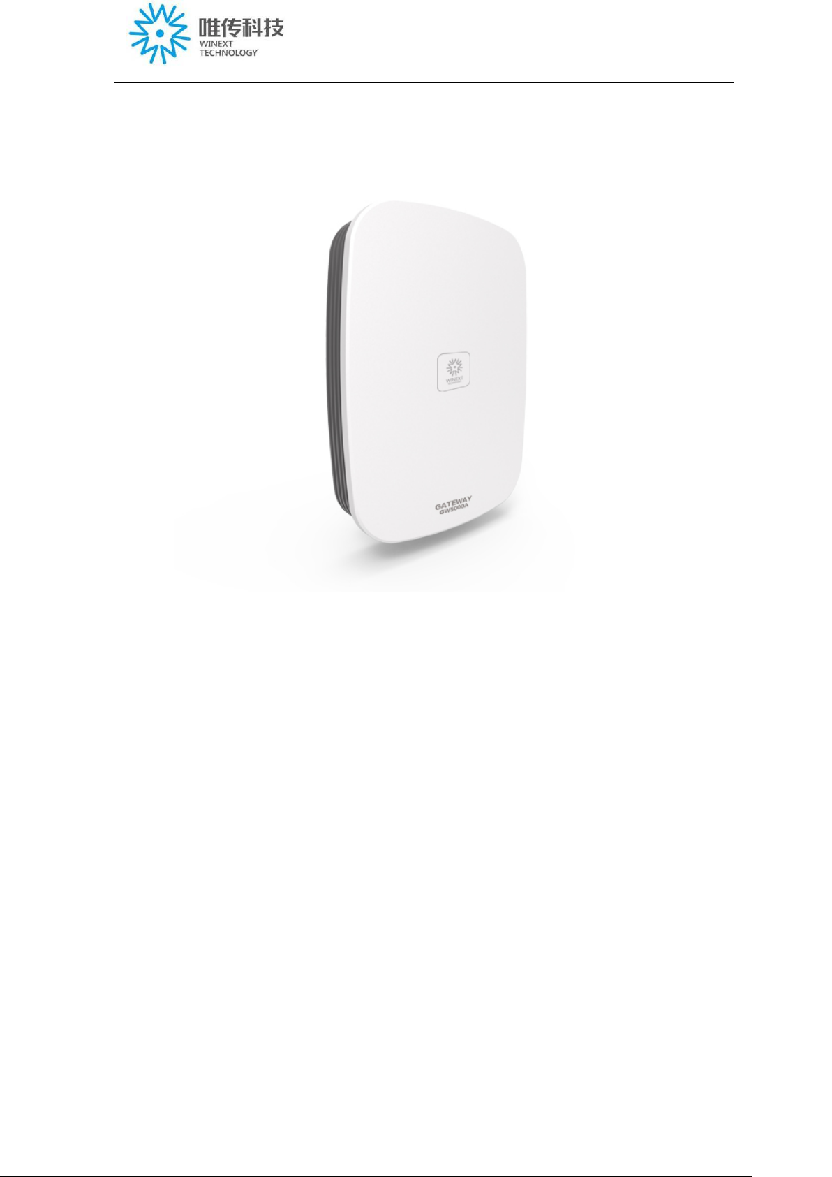
GW5000AIndustrial-grade gateway router
Product name: LoRaWAN gateway router
Model: GW5000A
Version: V3.4
Company name:Shenzhen Winext T e chnology Co., Ltd.
Address:Rm 505, Building B50, Zhongchuang Industrial Park,
Liuxian Rd, Taoyuan Street, Nanshan District, Shenzhen,
China
Tel: 0755-23990916
Fax: 0755-23990906
1
Page 2

Table of contents
Shenzhen Winext Technology Co., Ltd.
Packing list ............................................................................................................................. 4
Attention .................................................................................................................................. 5
Product introduction .............................................................................................................. 6
1. Product definition ............................................................................................................ 6
2. Interface introduction ...................................................................................................... 7
3. Basic information ............................................................................................................ 9
4. Restore factory setting ..................................................................................................... 9
5. Product dimension .......................................................................................................... 11
6. T echn ical paramete r ....................................................................................................... 12
7. Label .............................................................................................................................. 13
Installation: ........................................................................................................................... 14
1. SIM card installation ..................................................................................................... 15
2. Installation of antenna ................................................................................................... 16
3. Installation of the whole kit ........................................................................................... 17
4. Power supply instruction ............................................................................................... 18
Network setting ..................................................................................................................... 19
1.Routing mode of network ............................................................................................... 19
2. Wi-Fi setting .................................................................................................................. 21
3. Check the current network status ................................................................................... 23
4. Check the status of WAN(Ethernet) .............................................................................. 24
5. Check the network status of 4G ..................................................................................... 25
6. Enable/disable WAN port data entry ............................................................................. 26
Configuration/upgrade of gateway ..................................................................................... 27
1. Login .............................................................................................................................. 27
1.1. Gateway login by WI-FI hotspot of phone/laptop ................................................. 27
1.2. Gateway login on computer ................................................................................... 27
2. Configuration of gateway .............................................................................................. 28
2
Page 3

Shenzhen Winext Technology Co., Ltd.
2.1 Wired configuration ................................................................................................ 28
2.2 Wireless configuration ............................................................................................ 32
2.3 Firmware upgrade of gateway ................................................................................ 32
FAQ ........................................................................................................................................ 34
FCC Caution ......................................................................................................................... 37
3
Page 4
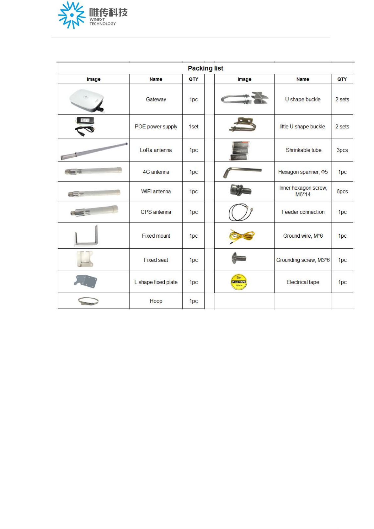
Packing list
Shenzhen Winext Technology Co., Ltd.
4
Page 5

Shenzhen Winext Technology Co., Ltd.
Attention
1) Gateway should be installed in the place with at least 20 degrees of depression angle
to building edges, and with at least 50cm clearance when installed at the side of a building
wall.
2) LoRa Omni directional antenna should be as far as possible from the other antennas,
and should be lower than the highest elevated point of the building.
3)The antenna should be installed vertically to the ground to achieve good effect.
4)Do the protection of lightning protection for gateway equipment, access network
cable of gateway, gateway antennas(surge arrester/lightning protector), and make sure
the antenna with the feeder to be connected to ground.
5)Using low power consumption RF coaxial cable of the feeder , as short as possible.
6)The feeder connector of antennas should be waterproof. If the feeder connector has
been flooded for a long time, the contact resistance of the connector is increased, the line
loss of the signal line is increased, and the antenna performance will be decreased.
7)If using 4G, you should choose a place with better L TE signal; The monthly traffic
plan should be more than 6G (depending on the number of nodes).
8)When the gateway is power on, the sequence of connection is: Firstly, connect one
end of network cable to gateway , and then the other end of the network cable to POE power
source or the end of POE exchanger, otherwise, the POE power source or POE exchanger
port will be damaged.
9)If using the PC side browser, it is strongly recommended that you use Google or
Firefox.
10) We suggest connecting POE splitter with backup power supply to prevent damage
of the log stored in TF card after power cut. If there is big data stored in TF card, it’ll take
long time to restore the log of the TF card after restarting th e gateway, and the gateway can
work normally after you finished restoring the log of TF card.
11)The product requires professional installation and the certified antennas should be
used.
5
Page 6

Shenzhen Winext Technology Co., Ltd.
Product introduction
1. Product definition
Winext Technology have launched the IoT base station gateway GW5000A based on low
power LoRaWAN protocol, which can provide low power, mobile and safe local
bidirectional communication service for IoT devices. LoRaWAN can simplify the
interconnection of device, user and network, as well as provide standard.
GW5000A is designed to be used in long rang e star network architectures; it can a chieve
message delivery between front-end device and central network server. GW5000A is
connected to the network server via standard IP connections while front-end devices use
single-hop wireless communication to one or many GW5000A gateways.
The communication between front-end devices and GW5000A is established by
different channels and data rate, which can be negotiated in advance. In order to save the
battery life, GW5000A can maximize the power saving by implementing ADR (Adaptive
Date Rate). With our IoT technology and our base station gateway GW5000A, users can
then have their own IoT control system to achieve customized smart services, which will be
widely applied in the f ields of smart p arking, smart fire-fighting, energy management, asset
tracking, smart grid, industry 4.0, smart agriculture and ect in the future.
6
Page 7
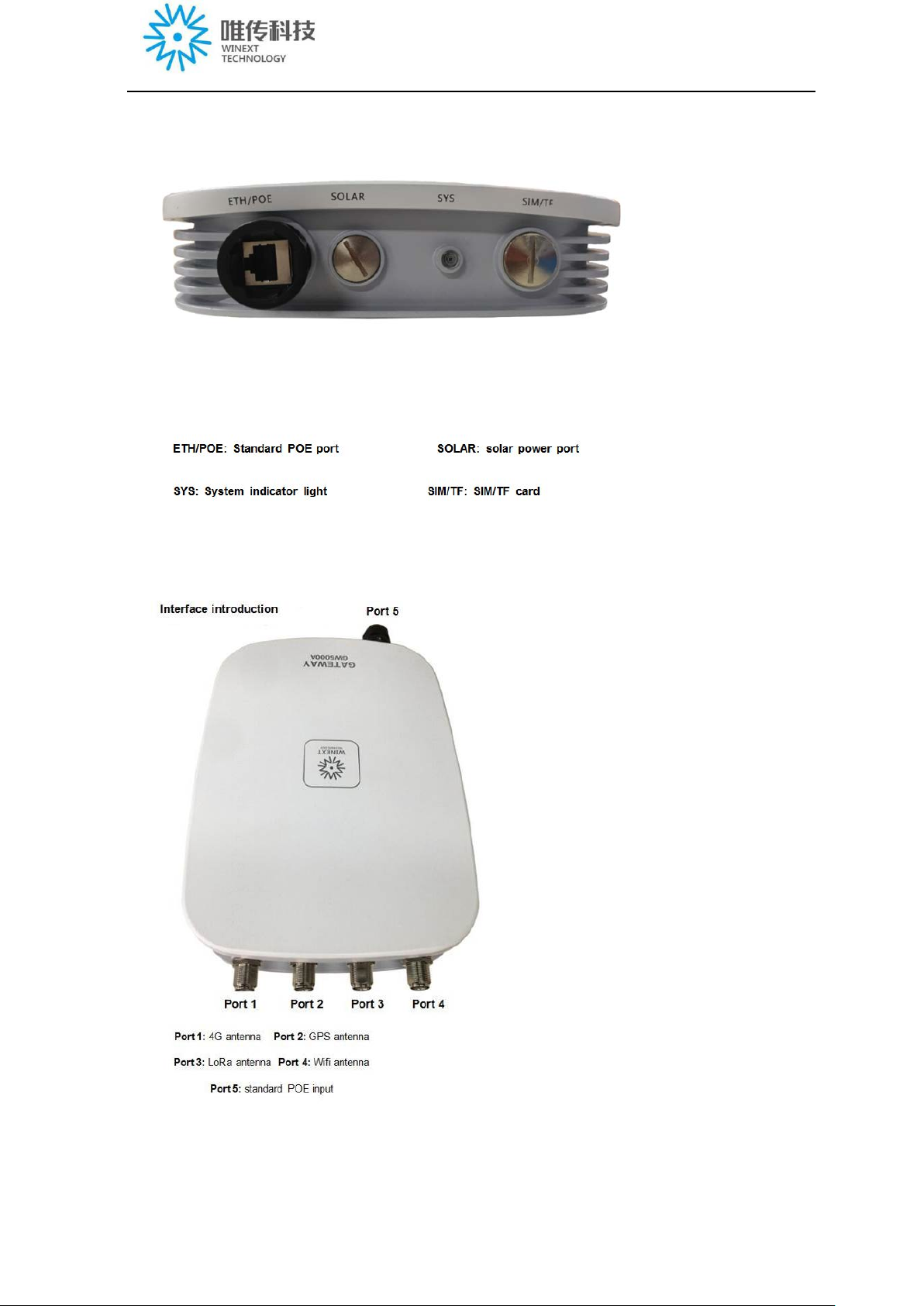
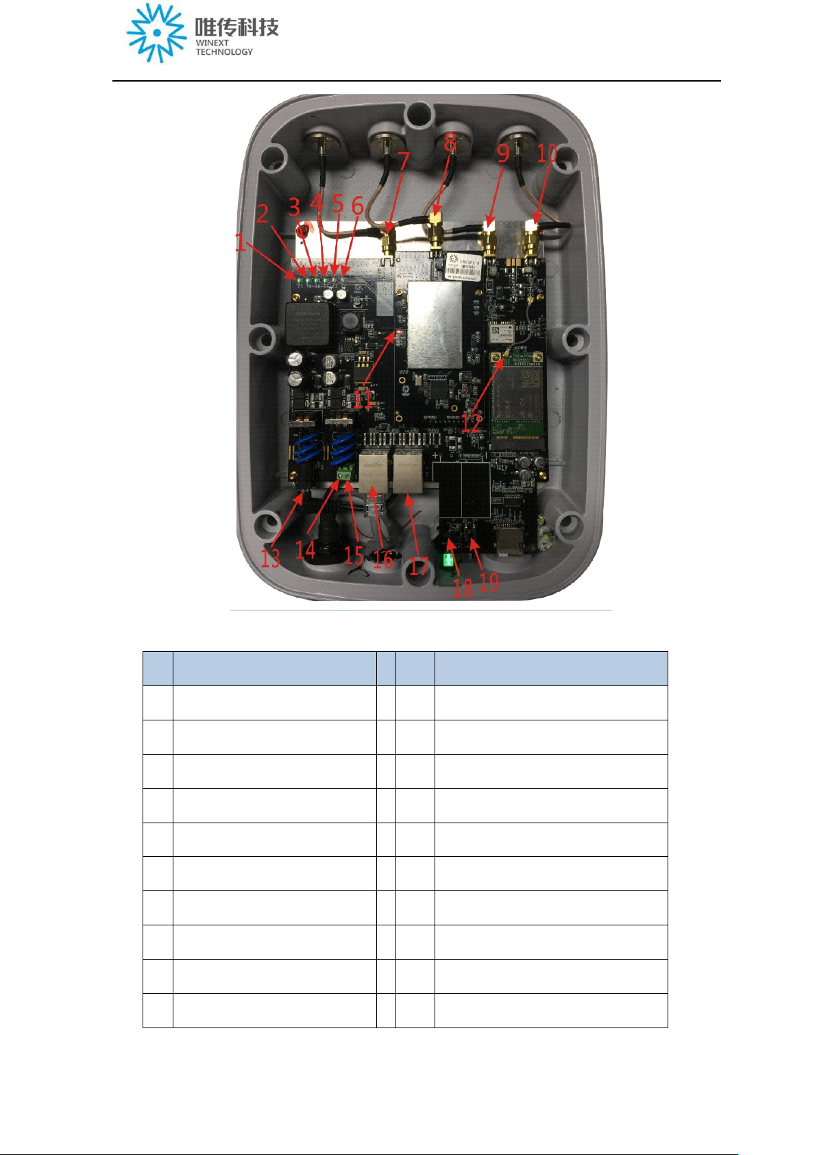
2. Interface introduction
Shenzhen Winext Technology Co., Ltd.
7
Page 8
Shenzhen Winext Technology Co., Ltd.
No Name No Name
1 POWER indicator 2 Wi-Fi indicator
3 USB indicator 4 WAN indicator
5 LAN in dicator 6 3G/4G indicator
7 SMA head port of WiFi antenna 8 SMA head port of LoRa antenna
9 SMA head port of GPS antenna 10 SMA head port of LTE antenna
11 Power indicator of SX1301 board 12 IPX port of the main antenna of 4G module
13 48V power port 14 Solar/standby power 12V grounding port
15 Solar/standby power 12V input port 16 WAN port
17 LAN port 18 Hardware reset button
19 Button to restore the factor y setti ngs
8
Page 9

Shenzhen Winext Technology Co., Ltd.
3.Basic information
1)LAN IP: 192.168.3.1, DHCP server is enabled by default;
2)Web page default user: root; login password: WelcomeTo2018;
3)WAN open DHCP client by default, need to connect with router;
4) 4G/LTE: Europe LTE, US 4G, support automatic dialing by default;
5) Wifi: 2.4GHz, AP mode, max transmit power:18dBm; W iFi hotspot:GW5000_+the end
6 characters of gateway ID; Password:gateway2018better
6)WAN and 4G network, priority in using the WAN traffic by default, 4G as a backup. When
WAN is not working, switch to 4G; Gateway needs to be able to get normal access to the internet,
network delay(ping lora.smartkit.io)less than 50ms, if using Ethernet, network speed should be
above 2M; If using 4G card, the monthly data access plan should be above 6G(it depends on the
nodes quantity)
7) The default fi le fo rmat of TFcard: FAT32, when the rest memory less than 2G, the oldest
log files will be cleared.
8)Support foreign server, e.g. TTN;
9)Support reporting status regularly(WAN, LTE, LoRa, WiFi, TF card)
10)Support reporting LoRa configuration parameter regularly;
11)Support remote reboot;
12)Support remote administrator login and maintenance;
13)Support button or WEB operation to restore factory setting;
14)For security reasons, root login SSH2 and serial port have been disabled, and the account
of login SSH2 and serial port is not open to the public.
4. Restore factory setting
If you’ve modified some parameters of gateway, andthe gateway won't work properly, there
are two methods to restore factory settings.
st
1) 1
method: press the reset button on the main board for more than 8 seconds(short press
will restart the system) , the reset button is as below:
9
Page 10
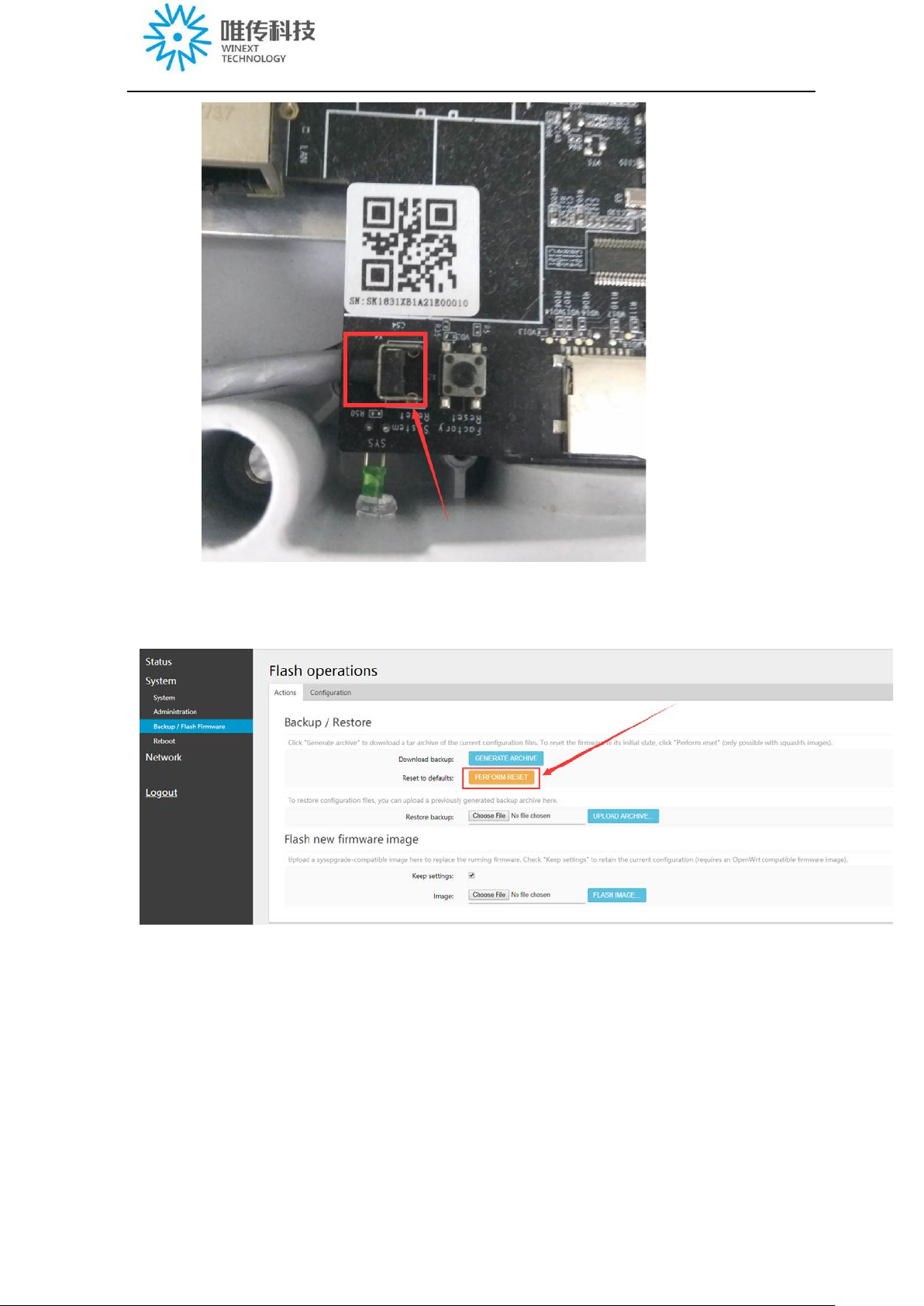
Shenzhen Winext Technology Co., Ltd.
2) 2nd method: Login the following interface:
Wait 1~2 minutes, then login.
10
Page 11
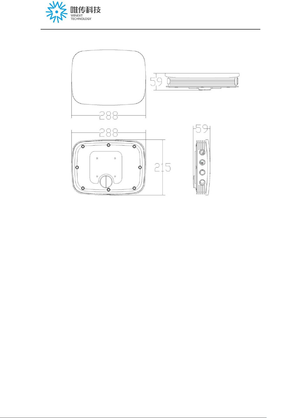
5. Product dimension
Shenzhen Winext Technology Co., Ltd.
11
Page 12
1xLTE module
6. Technical param eter
Shenzhen Winext Technology Co., Ltd.
Technical
parameter
Wireless
parameter
CPU
LoRa data rate
Ethernet
communication
rate
LTE
communication
rate
Industrial level CPU
Linux system
300bps~5.4Kbps
100Mbps
50Mbps
Electrical
specification
Physical
parameter
Rx sensitivity
Communication
interface
Input
Working
temperature
Working
humidity
IP grade
Dimension
Installation
Certificate
-143dBm
1xLAN ,1xWAN,1xWIFI,
POE power supply with 48V input(24~48V)
-30℃~65℃
10%~90%
IP67
288mm*215mm*59mm
Wall-mounted or with holding rod
CE/FCC
Thunder
protection
optional
12
Page 13

7.Label
Neutral label as below:
Shenzhen Winext Technology Co., Ltd.
Remark:
The “manufacturer address xxxxxx” and “importer name xxxxx, address xxxxx” shall be
provided on the product before the product into the market.Model on label above can be replaced
by other models.
13
Page 14

Installation:
Shenzhen Winext Technology Co., Ltd.
14
Page 15

Shenzhen Winext Technology Co., Ltd.
1. SIM card installation
Note: Supported LTE models as below:
Open the SIM/TF card slot cover with a large screwdriver:
15
Page 16

Shenzhen Winext Technology Co., Ltd.
Insert SIM card into the card slot with the chip side upwards and the notch inwards(there are
two card slots, the above one is for TF card, the below one is for SIM card):
2. Installati on of ant e nna
The gateway is mounted on a pole and the antenna is up, and from left to right, the
antennas are: Wifi antenna, LoRa antenna, GPS antenna, and 4G antenna, fix the
antenna to the corresponding interface, as below:
16
Page 17

Shenzhen Winext Technology Co., Ltd.
3. Installation of the whole kit
17
Page 18

4. Power supply instruction
Shenzhen Winext Technology Co., Ltd.
A) Powered by POE, as below:
(POE ports diagram)
Powered by solar panel
B)
Solar panel power supply includes: solar cell + photovoltaic controller + storage
battery
The connection as below:
Solar cell--photovoltaic controller – storage battery—gateway
Solar panel recommendation: solar panel voltage 18V, no less than 30W,
preferably with a controller; Storage battery: 12V/100Ah; The length of the 12V Power
line is less than 3m.
18
Page 19

Shenzhen Winext Technology Co., Ltd.
Network setting
1. Routing mod e of network
Splitter(exchanger) cable is connected to the WAN port, as below:
Remark:
The router that the gateway is connected must be able to connect to Internet, and you
should start the DHCP function for the router, and then the gateway automatically obtains
the IP. If you do not start DHCP, or because of network security management, you need
to assign a fixed IP to the gateway, then manually modify the assigned IP address in the
19
Page 20

Shenzhen Winext Technology Co., Ltd.
gateway interface, as below:
Select “Network/interfaces”, enter “interface overview”, come to WAN, then you can
choose “EDIT” to modify, as below:
In “interfaces-WAN”, choose the Protocol to “DHCP client” and then
“SAVE&APPLY”, then choose “Static address” in Protocol, then click “Switch protocol”,
as below:
20
Page 21

Shenzhen Winext Technology Co., Ltd.
Then, you’ll come to the below interface, and input the following items:
In “Advanced Settings”, modify the “Use gateway metric” to be 10, click
“SAVE&APPLY”, as below:
2. Wi-Fi setting
The default Wi-FiESSID: GW5000_+ the last 6 characters of gateway ID
The default password: gateway2018better
If you’d like to modify, click “Network/wireless/edit, as below:
21
Page 22

Shenzhen Winext Technology Co., Ltd.
Then, you’ll come to wireless network interface, pulldown to “Interface C
onfiguration”, in the “General Setup”, you can modify “ESSID”(wifi hotspot), then click
“SAVE&APPLY”, as below:
22
Page 23

Shenzhen Winext Technology Co., Ltd.
In “Wireless Security”, you can modify the password of wifi hotspot, click
“SAVA&APPLY”, as below:
3. Check the current ne twork status
Enter “Status/Overview”, as below:
Here, it shows that WAN is online, 4G is offline.
23
Page 24

Shenzhen Winext Technology Co., Ltd.
Enter “Network/Load Balance/Detailed Status”, you can check the details as
below:
4. Check the status of WAN(Ethernet)
Enter “Network/Interfaces”, as below:
Here, it shows run time and IP address, and RX and TX is not 0, it indicates the
WAN is normal.
24
Page 25

Shenzhen Winext Technology Co., Ltd.
5. Check the network status of 4G
Enter:
Network->4G/LTE
When deploying gateway, the network should be stable, and if there is no wired
network, we can also use 4G network, but we should choose a position with strong 4G
signal to deploy gateway.
Qualified LTE network should meet the following 2 points:
1)Network mode display:LTE(China Mobile: TDD, China Telecom and China
Unicom: FDD
2)Signal strength above 28(the network signal should be stable the whole day)
As below, it’s under unqualified network:
Here, it’s under unqualified network: weak signal and it’s not 4G network.
25
Page 26

Shenzhen Winext Technology Co., Ltd.
6. Enable/disable WAN port data entry
The WAN port data entry is enabled by default and the WAN port access gateway is
supported
Access the gateway page via the WAN port IP(e.g. if IP of the PC is 192.168.8.x, and
the gateway is 192.168.8.5, then access on the computer through a browser, enter:
192.168.8.5, you can directly access to the gateway), configuration as below(default
setting):
If you do not want to access the gateway via the WAN, you can use LAN or WiFi to enter
the Settings as follows:
26
Page 27

Shenzhen Winext Technology Co., Ltd.
Configuration/upgrade of gateway
1. Login
1.1.Gateway login by WI-FI hotspot of phone/laptop
Open the phone/laptop wi-fi setting and connect the GW5000Wi-Fi hotspot(Hotspot
name: GW5000_the last 6 characters of gateway ID; Password: gateway2018better),
as below:
1.2. Gateway login on computer
Using google browser on computer, login 192.168.3.1, you’ll enter the interface of
gateway login, input username and password (Username: root; Password:
WelcomeTo2018), as below:
27
Page 28

Shenzhen Winext Technology Co., Ltd.
2. Configuration of gateway
Note: The gateway configuration includes wired configuration and wireless
configuration. Wired configuration is achieved by using the network LAN port of the
computer to connect with gateway; Wireless configuration is achieve by using mobile
phone/laptop/PDA to connect to the gateway wi-fi hotspot.
2.1 Wired configuration
1)Connect the computer to the LAN port of gateway, and power on the gateway;
2)Using google browser to enter “192.168.3.1”, then you’ll come to the gateway
login interface, as below:(Username: root; Password: WelcomeTo2018)
3)Select “Network/LoRa GW/Configuration, then you’ll come to LoRa setting
interface, as below:
28
Page 29

Shenzhen Winext Technology Co., Ltd.
29
Page 30

Shenzhen Winext Technology Co., Ltd.
4)In the “Configuration/LoRa setting” interface, you can configure the “server address”,
“Enable LoRa Gateway”, “Store the log as txt file” ;
---Server address: choose your LoRa network server address, if there is nothing to choose,
pls click “Custom” in the bottom, and input your own LoRa network server address;
---Enable LoRa gateway: you should tick to choose it;
---Store the log as txt file: you should tick to choose it;
Finally, click SAVE&APPLY.
As below:
30
Page 31

Shenzhen Winext Technology Co., Ltd.
5)Check the network status of gateway, click “Network/Load Balancing/Overview”,
as below:
31
Page 32

Shenzhen Winext Technology Co., Ltd.
Here, it shows WAN is online, you can access Ethernet; 4G is offline or 4G SIM card
haven’t been installed.
6)Check the status of GPS, click “Network/LoRa GW”, you’ll come to GPS
overview, as below: (here, it shows the GPS is not in working status, as there is no
information)
7) After the above confirmation is normal, the gateway box is closed with
hexagonal screwdriver.
2.2 Wireless configuration
The steps are the similar as that of wired configuration, only displayed by
mobilephone/PDA/laptop.
2.3 Firmware upgrade of gateway
Enter “System/backup/Flash Firmware/Action”,
1)Keep settings: pls don’t tick to choose;
2)Choose file: Choose the provided version in .bin format;
3)Click “Flash image”As below:
32
Page 33

Shenzhen Winext Technology Co., Ltd.
After click “Flash image” , pls wait for a moment until the upload complete, then come to
the interface of “Flash Firmware-Verify”, as below:
Note: When file is finished uploading, wait and check to make sure the Checksum is
as same as that of md5 file(which will be sent to customer together with the bin format
file), if it’s the same, pls click PROCEED button. If the Checksum is not as same as that
of md5 file, it’s possible that the upload file damages. You should click CANCEL button
to re-upload, because the damaged file can make gateway to be brick. As below:
Note: After click PROCEED button, it’s flashing the firmware, pls make sure the
33
Page 34

Shenzhen Winext Technology Co., Ltd.
power supply be stable, and wait for 3~5 minutes until it finishes.
After finishing flash firmware, there is no need to enter the Web page, the gateway will
enable by default.
FAQ
1. Gateway will not work after a power failure
When there is a power failure, the log on the TF card is damaged, after restart gateway,
it’ll do self-check to automatically repair log, if TF card data quantity is large, it’ ll take a
long time to repair, in the process of repairing, the gateway is not working.
Solution: enter the configuration interface of gateway (192.168.3.1) , gateway login,
select “Network/LoRa GW/Status”, click “CLEAR THE LOG OF TF CARD”, as below:
After clear the log of TF card, pls restart the gateway, then it’ll work again.
34
Page 35

Shenzhen Winext Technology Co., Ltd.
2. GPS unable to locating
Enter 192.168.3.1 interface:
1) Check whether there is positioning information or not, if yes, it means GPS
is normal
2)Check whether there is time synchronization or not, as below:
If GPS is normal, the time synchronization should be less than 5 seconds, the above
picture shows “(age: 0 sec), that means the GPS is normal.
3)If GPS has no location information, you can re-plug the GPS antenna, or
repositioning in an open area, or update GPS antenna.
35
Page 36

Shenzhen Winext Technology Co., Ltd.
3.Nodes cannot access to the network
1)Check whether the gateway works normally or not.
2)Check whether there is power supply for nodes
3) Nodes power on
4.LoRa signal and data rate
)Received Signal Strength Indicator(RSSI)
1
125KHZband width, rate:300~5.4K bit/s, as below:
Note: the limit value of SF12 is -142. Generally speaking, if signal below -124 dBm, the
packet drop rate(PDR) will be high, normal value should be during -120dBm~ -40dBm.
2)Signal Noise Ratio(SNR)
Note: The limit value of SF12 is -20db, the limit value of SF10 is -15db. The closer it’s from
the limit value, the worse the signal.
The above data is based on the basis of the gateway test, if you use a node test, the data is
different.
36
Page 37

Shenzhen Winext Technology Co., Ltd.
FCC Caution
Any Changes or modifications not expressly approved by the party responsible for
compliance could void the userʹs authority to operate the equipment.
This device complies with part 15 of the FCC Rules. Operation is subject to the
Following two conditions:
(1) This device may not cause harmful interference, and
(2) This device must accept any interference received, including interference that maycause
undesired operation.
Radiation Exp osure Statement
This equipmen t co mplies with FCC radiation expos u re limits set forth for anuncontrolled
environment. This equipment should be installed and operated withminimum distance 20cm
between the radiator & your body.
Note: This equipment has been tested and found to comply with the limits for a Class B digital
device, pursuant to part 15 of the FCC Rules. These limits are designed to provide
reasonable protection against harmful interference in a residential installation. This
equipment generates, uses and can radiate radio frequency energy and, if not installed and
used in accordance with the instructions, may cause harmful interference to radio
communications. However, there is no guarantee that interference will not occur in a
particular installation. If this equipment does cause harmful interference to radio or television
reception, which can be determined by turning the equipment off and on, the user is
encouraged to try to correct the interference by one or more of the following measures:
—Reorient or relocate the receiving antenna.
—Increase the separation between the equipment and receiver.
—Connect the equipment into an outlet on a circuit different from that to which the receiver is
connected.
—Consult the dealer or an experienced radio/TV technician for help.
37
 Loading...