

Wine racks America Magnum/Champagne Kit Assembly Manual
Standard Connector
Magnum/Champagne Kit
Assembly GUIDE
Middle Ladder
End Ladder
Page 1
Questions?
888.373.6057
or visit
wineracksamerica.com
Standard Connector
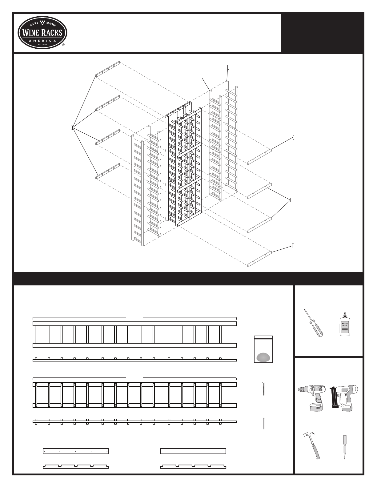
Package Contents tools for assembly
* All models follow the same assembly procedure varying only in the number of middle ladders your rack will require.
Depending on the model you purchased, your bundle should contain the following:
END LADDER ASSEMBLIES
77 1/8"
SIDE VIEW
MIDDLE LADDER ASSEMBLIES
77 1/8"
WOOD PUTTY
Screwless Connector
Standard Connector
Required
Screwdriver
Suggested
Wood Glue
SIDE VIEW
STANDARD CONNECTORS
(Various Lengths)
SIDE VIEW
SCREWLESS CONNECTORS
(Various Lengths)
SIDE VIEW
WOOD SCREWS
FINISH NAILS
Cordless Drill
Hammer
Finish Nailer
+
Nail Setter
Questions?
Magnum/Champagne Kit
Assembly GUIDE
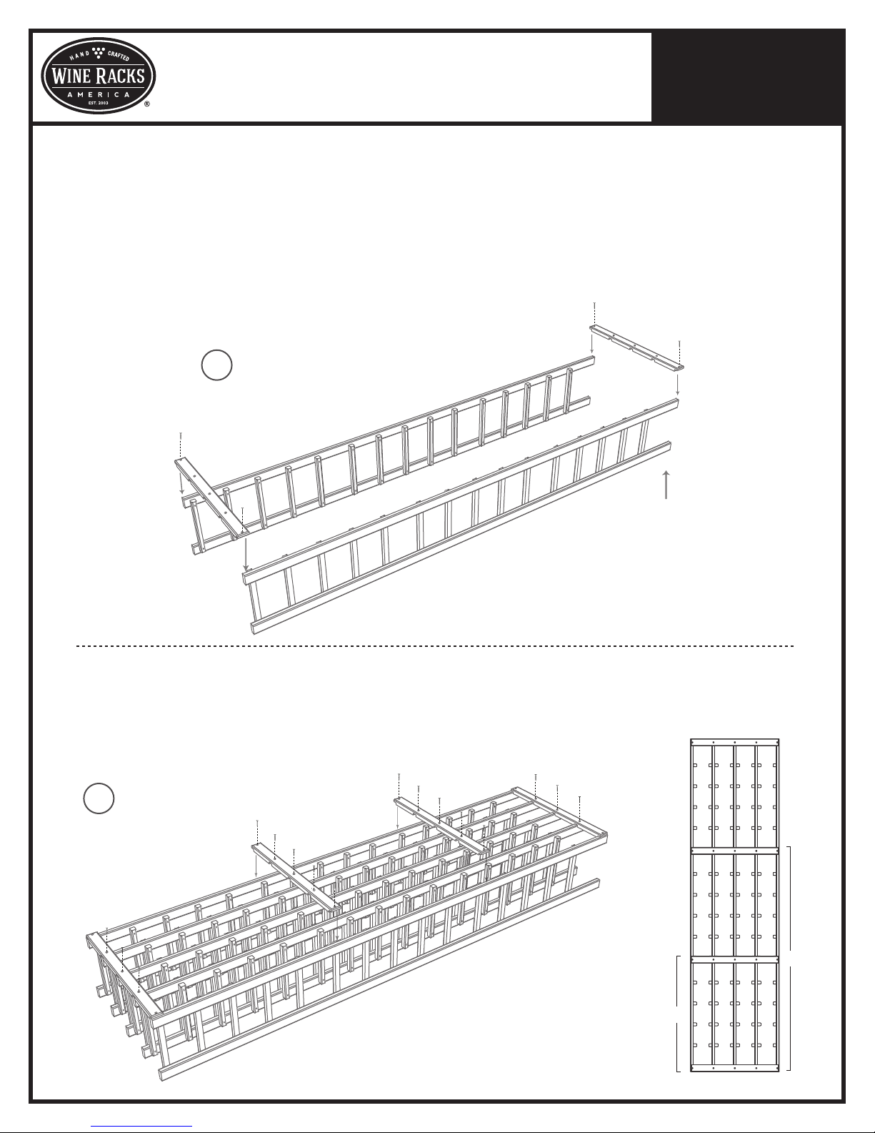
1. Find an open, flat area in which to work. Carefully remove all components from the box and remove banding
with a utility knife. Check the parts list to verify package contents.
2.
Arrange the end ladders on the floor so that the bottle support pieces face one another. Align the large gaps on each
end ladder. The end with the larger gap is the top of your rack. Attach a standard column connector to the top
and bottom of your rack using the screws provided. Make sure the connectors are flush with the top and bottom
of your rack. (figure 1)
* Minimize the risk of splitting your ladders by drilling a 1/16" pilot hole before driving the wood screws.
For best results, drive the screw most of the way in with your drill, then finish tightening by hand.
BEGIN WITH BACK
1
OF RACK
Page 2
888.373.6057
or visit
wineracksamerica.com
Top of rack
3. Insert the middle ladders and finish securing the top & bottom connectors using the screws provided.
4. Attach the middle standard connectors so that the top edge of the lower connector is 26 5/8" from the bottom
of the rack, and the top edge of the upper connector is 51 3/4" from the bottom of the rack. Secure the middle
connectors using the screws provided. This is the back of your rack. (figure 2)
FINISH SECURING BACK
2
CONNECTORS
51 3/4"
26 5/8"
Back of rack
 Loading...