

Wine Quality Solutions P300, P6000 User Manual
WWW.VINVENTIONS.COM
NOMASENSE O2 P300 & P6000
USER GUIDE

WWW.VINVENTIONS.COM
O2 P300 & P6000
CONTENT
• NomaSense or O2 P300 or P6000 oxygen
analyzer
• USB cable
• USB-Power adapter (5 VDC, min. 1 A) with
dierent connector pieces
• USB stick including the Datamanager Software
• Temperature probe PT100
• Short optical fiber
OPTIONAL
• Oxygen-sensitive chemical optical sensors (PSt3 or PSt6)
• Dipping probe (PSt3 or PSt6)
• Starter kit of accessories: white pen, spatula, silicone glue, one set of syringes, filling level gauge
ADDITIONALLY REQUIRED EQUIPMENT NOT SUPPLIED
• PC/notebook for comfortable data transfer and export:
System requirements:
Microsoft® Windows® XP, Vista™, 7, or 8; Processor power according to minimum requirements of the
respective operating system
Fig. 1 Case with all delivered equipment
WWW.VINVENTIONS.COM
O2 P300 & P6000
DESCRIPTION OF THE DEVICE
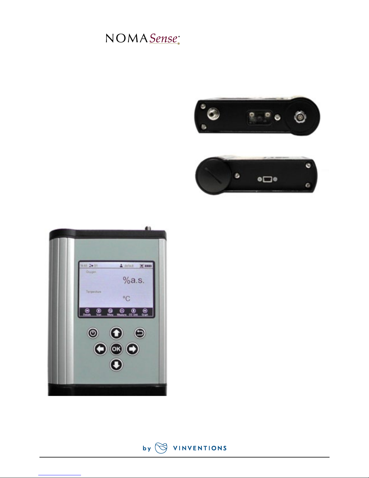
TOP PANEL
The top panel is equipped with a connector for the
fiber optic sensor, a connector for the temperature
sensor, and the QR code reader.
BOTTOM PANEL
The bottom panel is equipped with the USB
connector for charging the battery or connecting
the device to a PC/notebook. A screw cap gives
access to the battery compartment.
CONTROL PANEL
The NomaSense O2 P300 and P6000 are completely
stand-alone devices. The LCD display and the
buttons allow operating the transmitter without
connection to a PC/notebook. In the lower part
of the display the functions of the buttons in the
respective menu, submenu or window are shown.
Use the buttons for navigating on the screen, and
to make settings; pressing the respective button
will perform the respective function (see Fig. 4).
Fig. 4 Control panel of the NomaSense O2 P300 & P6000
Fig. 3 Transmitter bottom panel
Fig. 2 Transmitter top panel
SMA
BAT T
USB
QR
TEMP
 Loading...