

WIN Enterprises PL-80690 User Manual
User’s Manual
1
PL-80690
Networking Appliance
Desktop Intel Celeron (codename Bay Trail) Network System,
Four Copper GbE, CF, SATA and mini-PCIe
User’s Manual
Version 1.0
WIN Enterprises, Inc. June., 2014

User’s Manual
2
© Copyright 2014. All Rights Reserved
Manual Edition 1.0, June, 2014
This document contains proprietary information protected by copyright. All rights are reserved;
no part of this manual may be reproduced, copied, translated or transmitted in any form or by any
means without prior written permission of the manufacturer.
The content of this document is intended to be accurate and reliable; the original manufacturer
assumes no responsibility for any inaccuracies that may be contained in this manual. The
original manufacturer reserves the right to make improvements to the products described in this
manual at any time without prior notice.
Trademarks
IBM, EGA, VGA, XT/AT, OS/2 and PS/2 are registered trademarks of International Business
Machine Corporation (IBM).
Award is a trademark of Award Software International, Inc.
Intel is a trademark of Intel Corp.
RTL is a trademark of Realtek.
VIA is a trademark of VIA Technologies, Inc.
Microsoft, Windows, Windows NT and MS-DOS are either trademarks or registered trademarks
of Microsoft Corporation.
All other product names mentioned herein are used for identification purpose only and may be
trademarks and/or registered trademarks of their respective companies.
Limitation of Liability
While reasonable efforts have been made to ensure the accuracy of this document, the
manufacturer and distributor assume no liability resulting from errors or omissions in this
document or from the use of the information contained herein.
For more information on PL-80690 or other WIN Enterprises products, please visit our website:
www.win-ent.com.
For technical support send inquiries to:
sales@win-ent.com.
WIN Enterprises, Inc. June., 2014

User’s Manual
3
Table of Contents
Chapter 1. General Information .................................................................... 4
1.1 Introduction.............................................................................................. 4
1.2 Specifications .......................................................................................... 5
1.3 Ordering Information............................................................................... 6
1.4 Packaging ................................................................................................ 6
1.5 Precautions .............................................................................................. 7
1.6 System Layout ......................................................................................... 8
1.7 Board Dimensions................................................................................... 9
Chapter 2. Connector/Jumper Configuration............................................ 10
2.1 Connector/Jumper Location and Definition ........................................ 10
2.2 Connector and Jumper Setting ............................................................ 12
2.3 CompactFlashTM Card Socket Pin Define ............................................ 18
Chapter 3. BIOS Setup ................................................................................ 19
3.1 Quick Setup............................................................................................ 19
3.2 Entering the BIOS Setup Utility ............................................................ 20
3.3 Menu Options......................................................................................... 21
3.4 Advanced Menu ..................................................................................... 22
3.4.1 Platform function................................................................................ 23
3.4.2 NCT6791D Super IO Configuration ................................................... 24
3.4.3 NCT6791D HW Monitor ...................................................................... 25
3.4.4 IDE Configuration. .............................................................................. 26
3.4.5 USB Configuration ............................................................................. 27
3.4.6 Hardware Health Configuration......................................................... 28
3.4.7 Console Redirection........................................................................... 29
3.5 Boot Menu.............................................................................................. 30
3.6 Security Menu ........................................................................................ 31
3.7 Chipset Menu ......................................................................................... 32
3.8 Chipset Menu ......................................................................................... 35
Chapter 4. Utility & Driver Installation…………………………....……………37
Appendix A: Programming the Watchdog Timer...................................... 39
Appendix B: Cable development kit .................Error! Bookmark not defined.
WIN Enterprises, Inc. June., 2014

User’s Manual
4
Chapter 1. General Information
1.1 Introduction
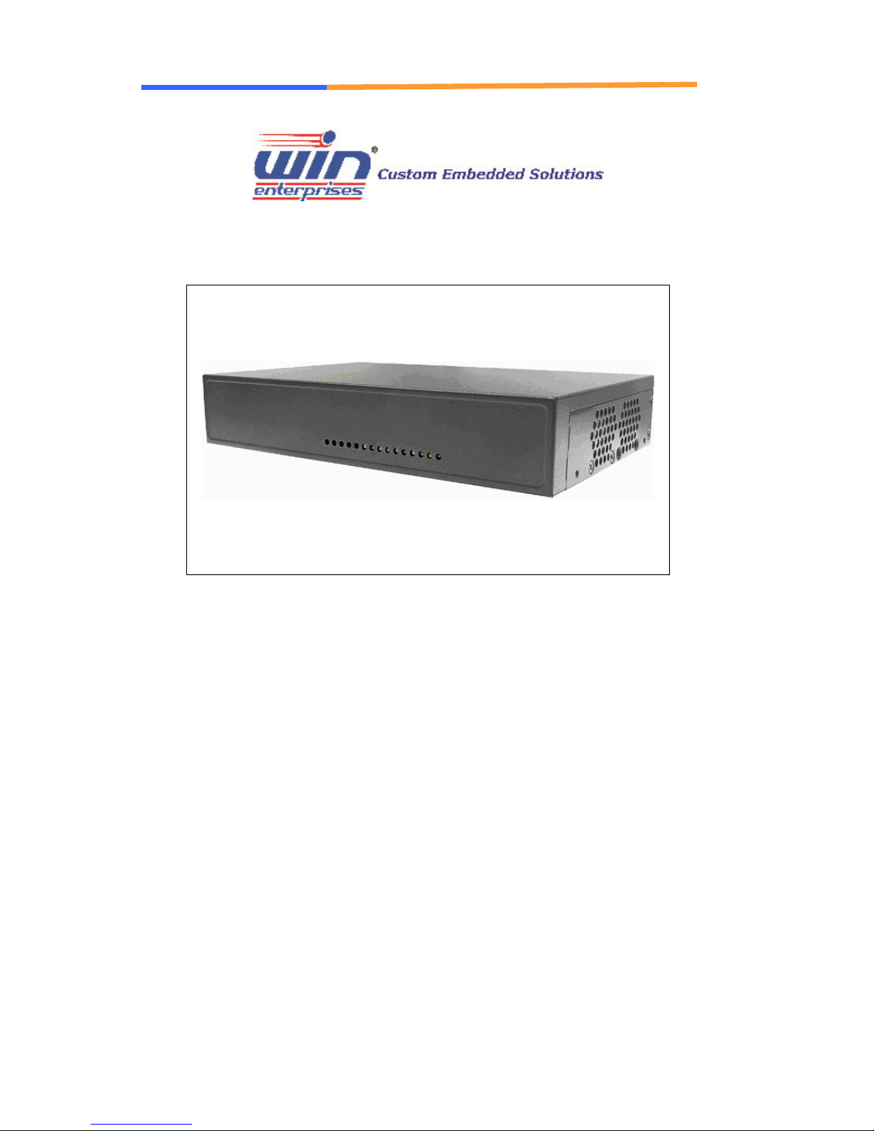
The PL-80690 is an affordable cost effective desktop platform designed for network service
applications. Built with Intel® Embedded IA components with warranty of longevity, the PL-80690
supports Intel® Celeron® Bay Trail-D, Bay Trail-I and Bay Trail-M low-voltage processors.
The platform supports onboard DDR3L memory chips with a maximum capacity of 2GB. In order
to provide the best network performance and utilization. The standard device comes equipped
with 4GB eMMC storage and interfaces including one 2.5” SATA HDD and CompactFlash™.
For network security, the PL-80690 is equipped with 4 Copper GbE, USB2.0 ports, RJ-45
console port and an optional mini-card socket with LED indicators that monitor power, storage
device activities for local system management, maintenance and diagnostics.
WIN Enterprises, Inc. June., 2014
5
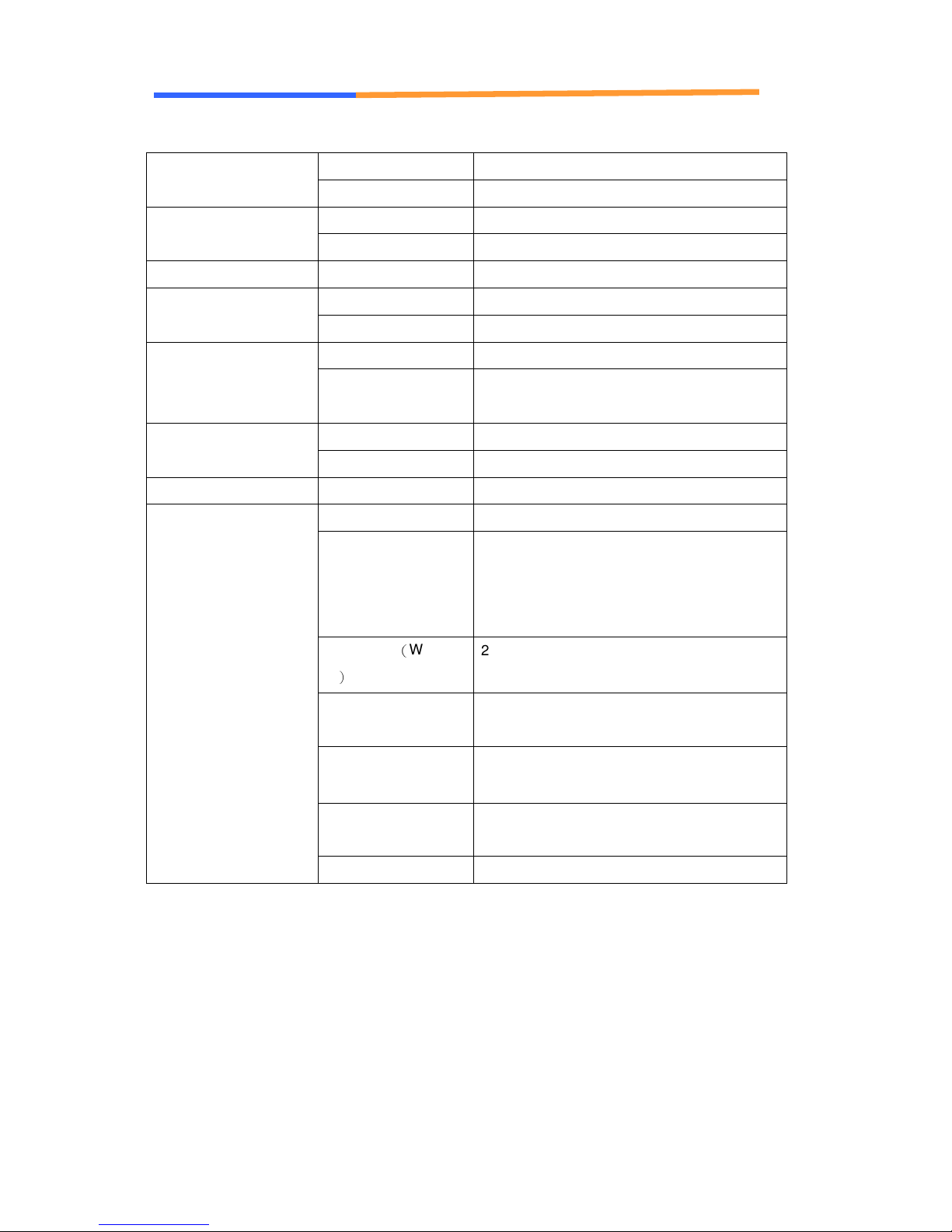
1.2 Specifications
Processor System
User’s Manual
CPU Intel® E3815 (Bay Trail-I) Processors
BIOS AMI UEFI BIOS
Memory
Expansion Expansion Slots One mini-PCIe socket via PCI-E x1.(Option)
Ethernet
Power Supply Watt 40W power supply, AC to DC 12V
Mechanical and
Environment
Technology
Capacity Up to 2GB
GbE Ethernet Four Copper GbE ports, Intel I211, PCI-E x1
LAN bypass N/A
SATA HDD One internal 2.5” SATA HDD bay Storage
Compact Flash
Socket
USB Two external USB2.0 I/O
Serial One RJ45 Console port (COM1)
Form Factor Desktop
LED Power LED
Dimension(W x D x
H)
Onboard DDR3L memory.
one CompactFlash
HDD LED
4 pairs LEDs for 4 Ethernet ports Active/Link
status
232mm (W) x 153mm (D) x 44mm (H)
(9.1W x 6” D x 1.7” H)
TM
Type II
Operating
Temperature
Storage Temperature
Humidity 10 ~ 85% relative humidity, non-operating,
Certifications CE/FCC
Operating: 0 ~ 40°C ( 32 ~ 104°F )
-20 ~ 75°C (-4 ~ 167°F)
non-condensing
WIN Enterprises, Inc. June., 2014

User’s Manual
6
1.3 Ordering Information
We offer some accessories for PL-80690 appliance for customer need.
PL-8069A Desktop Intel Bay Trail E3815
Network System, 4x GbE, 1GB
onboard DDR3 Memory, 4GB eMMC
and SATA
PL-8069B Desktop Intel Bay Trail E3815
Network System, 3x GbE, 1GB
onboard DDR3 Memory, 4GB
eMMC, SATA and mini-PCIe
PL-8069C Desktop Intel Bay Trail E3815
Network System, 4x GbE, 1GB
onboard DDR3 Memory, CF, SATA
and mini-PCIe (via USB)
Optional
DK Cable development kit
CB-CO5204-00 Cross over 2M
CB-EC5200-00 Ethernet cat.5 cable
2M
CB-RJDB91-00 RJ-45 to DB-9 cable
2M
CB-IVGA01-00 VGA cable
1.4 Packaging
Please make sure that the following items have been included in the package
before installation:
1. PL-80690 Appliance
2. Quick Installation Guide (Optional)
3. Cables (Optional)
If any item of above is missing or damaged, please contact your dealer or retailer
from whom you purchased the PL-80690. Keep the box and carton for possible
future shipment or storage. After you unpack the goods, inspect and make sure
the product is intact. Do not plug the power adapter to the appliance if it appears
damaged.
WIN Enterprises, Inc. June., 2014

User’s Manual
7
Note: Keep the PL-80690 in the original packaging until you start installation.
1.5 Precautions
Please make sure you properly ground yourself before handling the PL-80690
appliance or other system components. Electrostatic discharge can be easily
damage the PL-80690 appliance.
Do not remove the anti-static packing until you are ready to install the PL-80690
appliance.
Ground yourself before removing any system component from its protective
anti-static packaging. To ground yourself, grasp the expansion slot covers or
other unpainted areas of the computer chassis.
Handle the PL-80690 appliance by its edges and avoid touching the components
on it.
WIN Enterprises, Inc. June., 2014
8
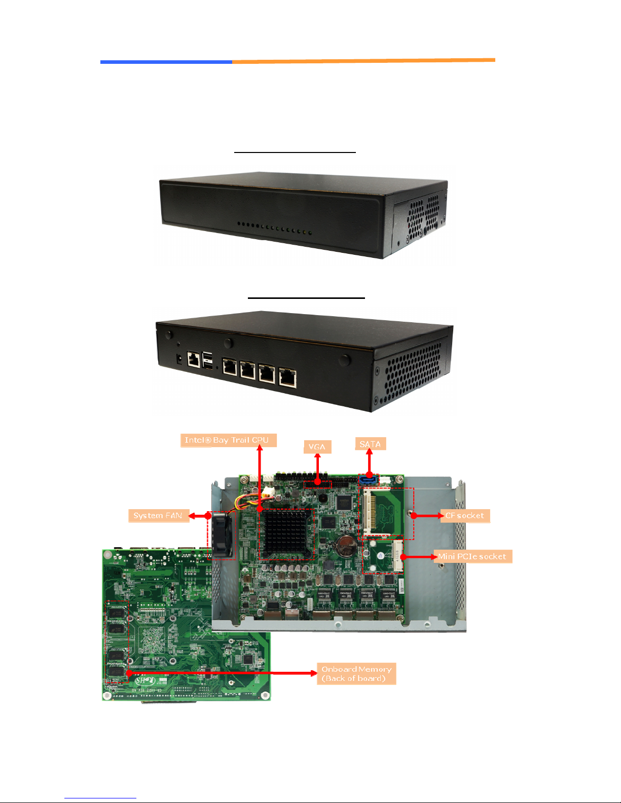
1.6 System Layout
User’s Manual
PL-80690 Front Side
PL-80690 Rear Side
WIN Enterprises, Inc. June., 2014
9
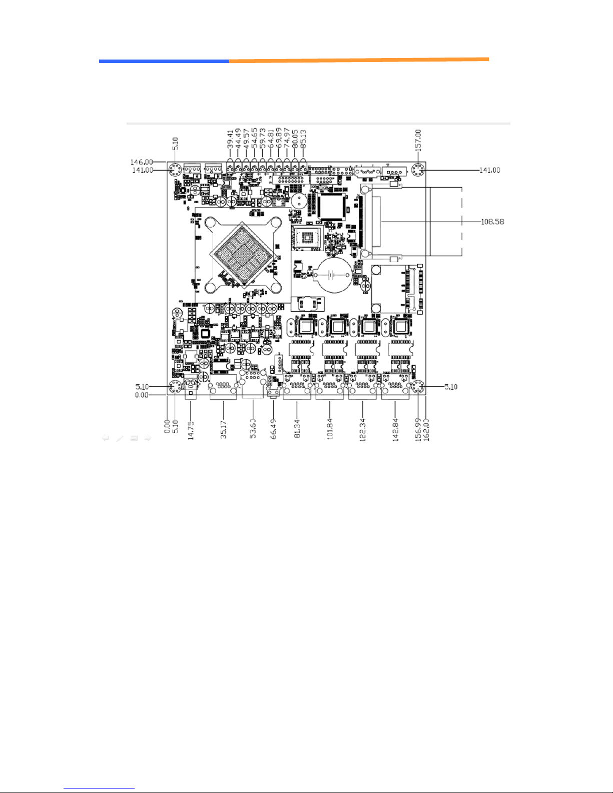
1.7 Board Dimensions
User’s Manual
WIN Enterprises, Inc. June., 2014
User’s Manual
10
Chapter 2. Connector/Jumper Configurations
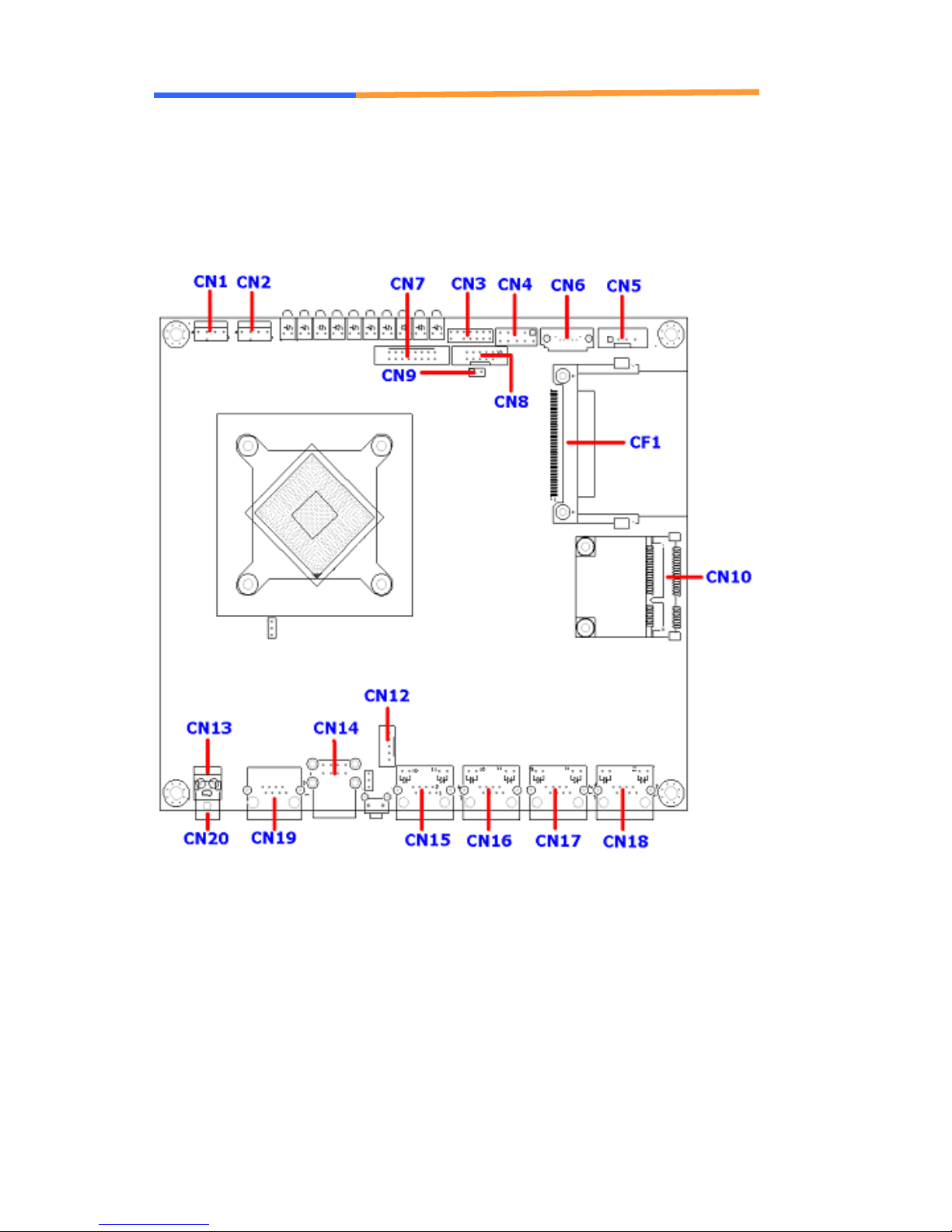
2.1 Connector/Jumper Location and Definitions
WIN Enterprises, Inc. June., 2014

User’s Manual
11
CB-6902 Connectors and Jumpers:
CN1 SYSTEM FAN
CN2 CPU FAN
CN3 LPC (Pin Header)
CN4 PS2 KB/MS Pin Header (Option)
CN5 SATA Power Connector
CN6 SATA Connector
CN7 VGA (Pin Header)
CN8 COM2 Pin Header (Option)
CN9 Debug GPIO(For Test Only)
CN10 MINI-PCIE
CN11
CN12 USB Port 2 (Option)
CN13 Power Connector (Option)
CN14 USB Port 0/1
CN15 LAN1
CN16 LAN2
CN17 LAN3
CN18 LAN4
CN19 Console
CN20 DC Jack
WIN Enterprises, Inc. June., 2014
User’s Manual
12
2.2 Connector and Jumper Settings
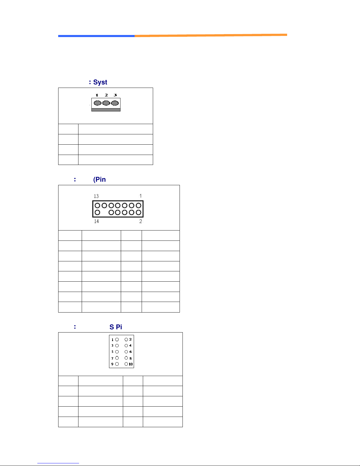
CN1/CN2
Pin Define
1 Ground
2 +12V
3 Speed Detect
CN3
::::
System/CPU FAN
::::
LPC (Pin Header)
Pin Define Pin Define
1 +3.3V 2 AD 0
3 AD1 4 AD 2
5 AD 3 6 Frame#
7 PCIERST#
8 +5V
9 CLOCK 10 PME#
11 GND 12
13 SERIRQ 14 DRQ#
CN4
::::
PS2 KB/MS Pin Header
Pin Define Pin Define
1 KCLK 2 MCLK
3 KDAT 4 MDAT
5 N/A 6 N/A
7 PS2_GND 8 PS2_GND
WIN Enterprises, Inc. June., 2014
User’s Manual
13
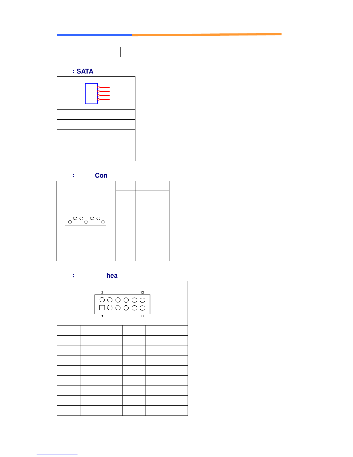
9 PS2_VCC 10 PS2_VCC
CN5
::::
SATA PWR
Pin Define
1 +12V
2 GND
3 GND
4 +5V
CN6
::::
SATA Connector
1
2
3
4
Pin Signal
1 Ground
2 TXP
3 TXN
4 Ground
5 RXN
6 RXP
7 Ground
CN7
::::
VGA (Pin header)
Pin Define Pin Define
1 RED 2 GREEN
3 BLUE 4 Reserved
5 GND 6 RED PTN
7 GREEN PTN
9 +5V 10 GND
11 Reserved 12 SDA
13 HSYNC 14 VSYNC
15 SCL 16 Reserved
WIN Enterprises, Inc. June., 2014
8 BLUE RTN
 Loading...