

WIN Enterprises PL-80350 User Manual
User ’s Manual
User’s Manual
Version 0.1
Networking Appliance
PL-80350 (Prototype): 1U Rack-Mount Intel® Atom Pineview Network
System, 6 GbE, SATA, CF, mini-PCI, PCI, and bypass
consultants@win-ent.com
+ 1 (978) 688-2000
WIN Enterprises, Inc. JUL., 2011
1

User ’s Manual
© Copyright WIN Enterprises. All Rights Reserved
Manual Edition 1.0, Jul., 2011
This document contains proprietary information protected by copyright. All rights are reserved; no
part of this manual may be reproduced, copied, translated or transmitted in any form or by any means
without prior written permission of the manufacturer.
The content of this document is intended to be accurate and reliable; the original manufacture r assumes
no responsibility for any inaccuracies that may be contained in this manual. The original
manufacturer reserves the right to make improvements to the products described in this m anual at any
time without prior notice.
Trademarks
IBM, EGA, VGA, XT/AT, OS/2 and PS/2 are registered trademarks of International business Machine
Corporation
Award is a trademark of Award Software International, Inc
Intel is a trademark of Intel
RTL is a trademark of Realtek
VIA is a trademark of VIA Technologies, Inc
Microsoft, Windows, Windows NT and MS-DOS are either trademarks or regis tered trademarks of
Microsoft Corporation
All other product names mentioned herein are used for identification purpose on ly and m ay be
trademarks and/or registered trademarks of their respective companies
Limitation of Liability
While reasonable efforts have been made to ensure the accuracy of this document, the manufacturer
and distributor assume no liability resulting from errors or omissions in this doc ume nt, or from the use
of the information contained herein.
For more information on PL-80350 or other WIN Enterprises products, please visit our website
http://www.win-ent.com .
For technical supports or free catalog, please send your inquiry to
sales@win-ent.com .
WIN Enterprises, Inc. JUL., 2011
2

User ’s Manual
Table of Contents
Chapter 1. General Information...............................................................................4
1.1 Introduction........................................................................................................4
1.2 Specifications.....................................................................................................5
1.3 Ordering Information.........................................................................................6
1.4 Packaging...........................................................................................................6
1.5 Precautions.........................................................................................................7
1.6 System Layout ...................................................................................................8
1.7 Board Dimensions..............................................................................................9
Chapter 2. Connector/Jumper Configuration.........................................................10
2.1 Connector/Jumper Location and Definition.....................................................10
2.2 Connector and Jumper Setting................................................................. ........10
2.3 CompactFlash
Chapter 3. Optional GbE Module & Riser Card Setting .......................................16
3.1 PM-104: Ethernet module with four 10/100 switch ports ...............................16
3.2 PM-108: Ethernet module with eight 10/100 switch ports..............................16
Chapter 4. BIOS Setup...........................................................................................17
4.1 Quick Setup......................................................................................................17
4.2 Entering the CMOS Setup Program.................................................................18
4.3 Menu Options...................................................................................................20
4.4 Advanced Menu...............................................................................................20
4.5 PCIPnP Menu...................................................................................................35
4.6 Boot Menu .......................................................................................................37
4.7 Security Menu..................................................................................................41
4.8 Chipset Menu...................................................................................................43
4.9 Exit Menu .......................................................................................................48
Chapter 5. Utility & Driver Installation.................................................................50
5.1 Operation System Supporting..........................................................................50
5.2 System Driver Installation ...............................................................................51
5.3 LAN Driver Installation...................................................................................51
Appendix A: Programming the Watchdog Timer ..................................................52
Appendix B: LAN Bypass Function......................................................................55
Appendix C: System Resources.............................................................................56
Appendix D: Cable Development Kit....................................................................60
Appendix E: Prototype PL-80350 Assembly Instructions.....................................61
TM
Card Socket Pin Define........................................................16
WIN Enterprises, Inc. JUL., 2011
3

User ’s Manual
Chapter 1. General Information
1.1 Introduction
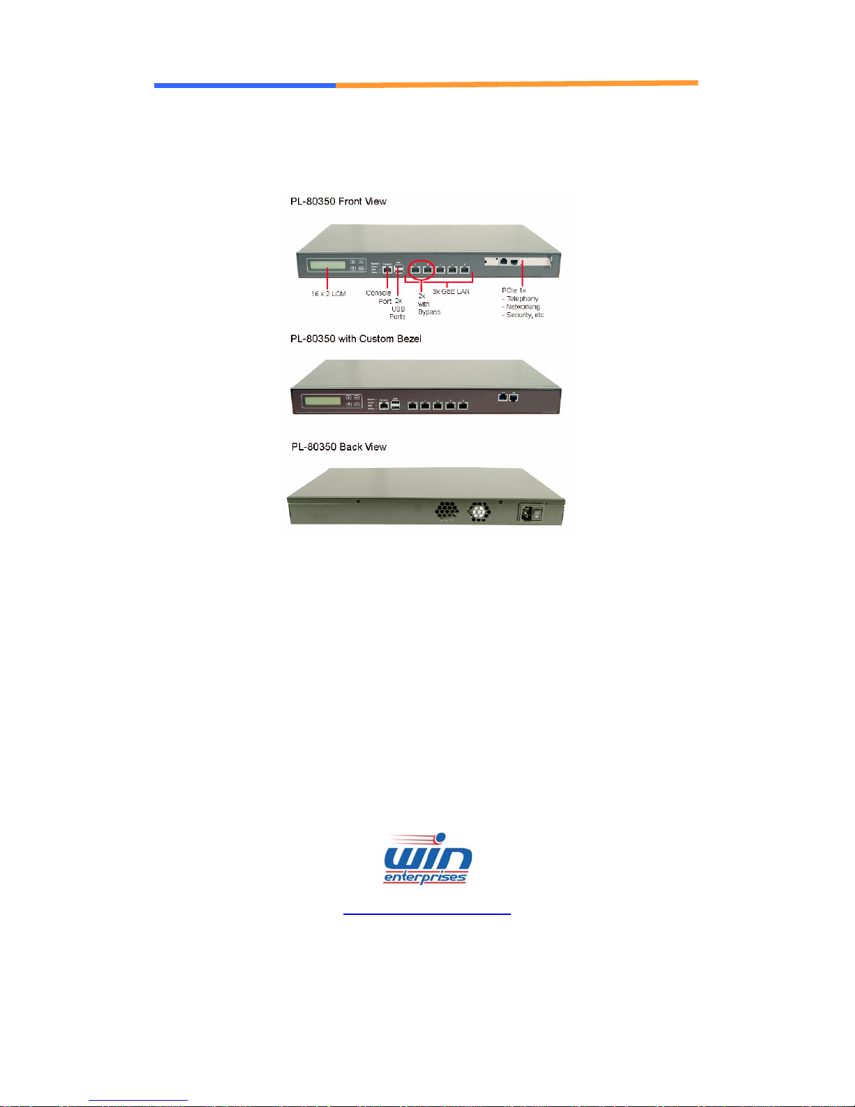
The PL-80350 is a 1U rack-mounted hardware platform designed for network
service applications. Built with Intel Embedded IA compo nent s with warr anty of
longevity, the PL-80350 supports Intel® Pineview-D low-v olt age processor with
Intel Pineview D525/D425 CPU and ICH8-M I/O controller.
The platform supports a high bandwidth DDR3 SODIMM slot with memory up
to 4GB. In order to provide the best network performance and best utilization,
powerful storage interfaces include one 3.5" SATA HDD and CompactFlash™.
PL-80350 affords six GbE Copper with bypass function or 5 GbE Copper with
bypass function and PCIe x1 expansion to the front bezel. The f ront panel also
has two USB 2.0 ports, one RJ-45 console port and LED indicators that
monitor power and storage device activities for local system management,
maintenance and diagnostics. In addition, the PL-80350 supports one Mini PCI
socket, one PCI slot, and is RoHS, FCC **PENDING** and CE **PENDING**.
WIN Enterprises, Inc. JUL., 2011
4

1.2 Specifications
Processor System
User ’s Manual
CPU Intel® Atom D525, D425 Processors
Chipset Intel® Pineview + ICH8-M chipset
BIOS
Memory
Expansion Expansion Slots one MiniCard expansion slot (USB Only)
Ethernet
Power Supply Watt 60W power supply, AC to DC 12V
Technology
Capacity Up to 4GB with one SO-DIMM socket
GbE Ethernet
LAN bypass Two ports bypass (Optional)
SATA HDD One internal 3.5” SATA HDD bay Storage
Compact Flash
Socket
USB two external USB2.0 I/O
Serial one RJ45 Console port (COM1, RS232)
AMI® BIOS
Un-buffered and Non-ECC DDR3 800 MHz
memory
one PCI-E x1 c onnector for expansion ris er card
six RJ45 GbE ports, Intel 82574L, PCI-E x1 (one
pair bypass between LAN1 and LAN2)
one CompactFlash
one internal 5x2 pin header (COM2)
TM
Type II
Mechanical and
Environment
Weight 1pc/CTN, 4.5kgs, 59cm (W) x 43.2cm (D) x 16cm (H)
Form Factor 1U rack-mount
LCD Module one 16x2 LCM
Keypad Four buttons keypad
LED one Bypass LED (Green)
one Power LED (G re en)
one HDD LED (Yellow)
one Status LED (Green/Yellow via
programmable GPIO)
Dimensions, W x
D x H
Operating
Temperature
Storage
Temperature
Humidity 10 ~ 85% relative humidity, non-operating,
432mm (W) x 270mm (D) x 44mm (H); 17” (W) x
8” (D) x 1.7” (H)
0 ~ 40°C ( 32 ~ 104°F )
-20 ~ 75°C (-4 ~ 167°F)
non-condensing
WIN Enterprises, Inc. JUL., 2011
5

User ’s Manual
Certification
1.3 Ordering Information
We offer the following standard variations for the PL-80350 appliance.
PL-8035A 1U rack-mount Intel® D525 CPU, 5 GbE, CF, SATA, LCM, bypass, PCIe
PL-8012B 1U rack-mount Intel® D425 CPU, 5 GbE, CF, SATA, LCM, bypass, PCIe
DK001 Cable development kit
CE/FCC **PENDING**
x1 Expansion
x1 Expansion slot.
CB-CO5204-00 Cross over cable
CB-EC5200-00 Ethernet cable
CB-RJDB91-00 RJ45 Console cable
CB-DB9200-01 Null modem cable
CB-IVGA01-00 VGA cable
CB-IPS200-00 KB/MS cabl e
CB-IUSB01-00 USB cable
1.4 Packaging
Please make sure that the following items have been included in the package
before installation.
1. PL-80350 Appliance
2. Quick Installation Guide (Optional)
3. Cables (Optional)
4. CD-ROM that contains the following folders:
(1) Manual
(2) System Driver
(3) Ethernet Driver
(4) Utility Tools
If any of the above items is missing or damaged please contact your dealer or
retailer from whom you purchased the PL-80350. Keep the box and carton if
you plan to ship or store PL-80350 in near future. After you unpack the goods,
inspect and make sure the packaging is intact. Do not plug the power adapter
to the appliance of PL-80350 if you find it appears damaged.
WIN Enterprises, Inc. JUL., 2011
6

User ’s Manual
Note: Keep the PL-80350 in the original packaging until you start installation.
1.5 Precautions
Please make sure you properly ground yourself before handling the PL-80350
appliance or other system components. Electrostatic discharge can be easily
damage the PL-80350 appliance.
Do not remove the anti-static packing until you are ready to install the
PL-80350 appliance.
Ground yourself before removing any system component from its protective
anti-static packaging. To ground yourself grasp the expansion slot covers or
other unpainted parts of the computer chassis.
Avoid touching the components within it.
WIN Enterprises, Inc. JUL., 2011
7
User ’s Manual
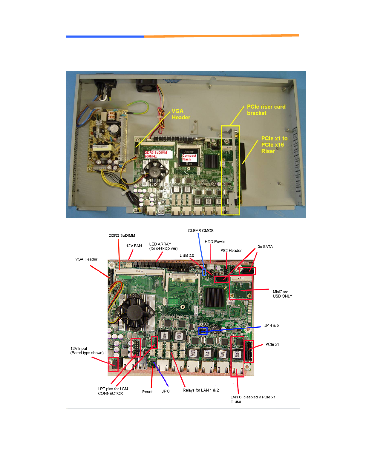
1.6 System Layout (Internal)
WIN Enterprises, Inc. JUL., 2011
8

1.7 Board Dimensions
Pictures Pending
User ’s Manual
WIN Enterprises, Inc. JUL., 2011
9
User ’s Manual
Chapter 2. Connector/Jumper Configuration
2.1 Connector/Jumper Location and Definition
Connectors and Jumpers:
Connector Define Connector Define
CN1 FAN Connector CN3 COM2 Pin Header
CN4 SATA Connector CN5 SATA Connector
CN6 PS2 KB/ MS Pin Header CN7 USB Pin Header
CN10 DDR3 SLOT CN11 VGA PORT
CN14 LCM KEY Pin Header CN12 FAN Connector
CN17 POWER Pin Header CN15 LCM Pin Header
CN19 LAN CONNECTOR CN18 USB CONNECTOR
CN21 LAN CONNECTOR CN20 LAN CONNECTOR
CN23 LAN CONNECTOR CN22 LAN CONNECTOR
CN25 COM1 CONNECTOR CN24 LAN CONNECTOR
PW1 HDD POWER PCIe SLOT
SW1 RESET/GPI BUTTON JP2 CLEAR CMOS
JP4 SELECT
WATCHDOG/BYPASS
JP8 SELECT RESET/GPI JP5 SELECT BYPASS
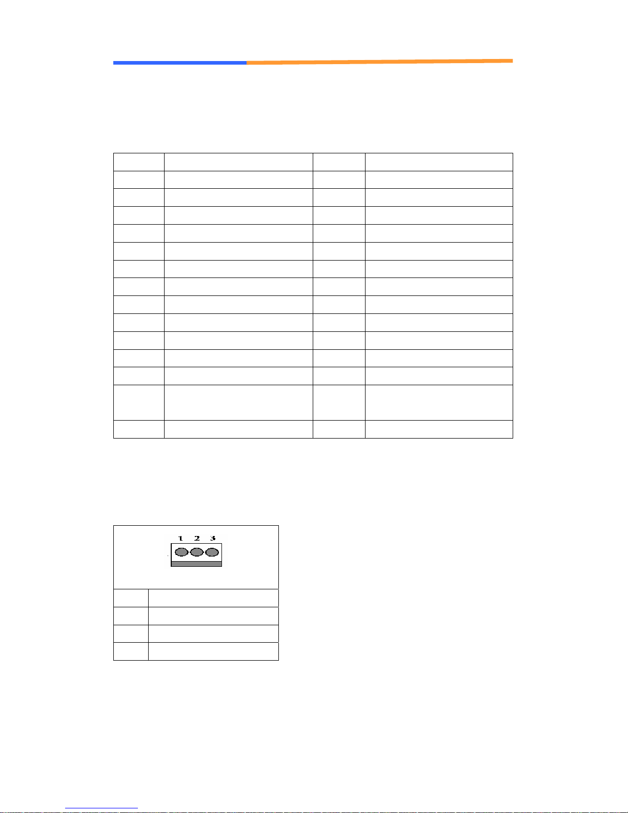
2.2 Connector and Jumper Settings
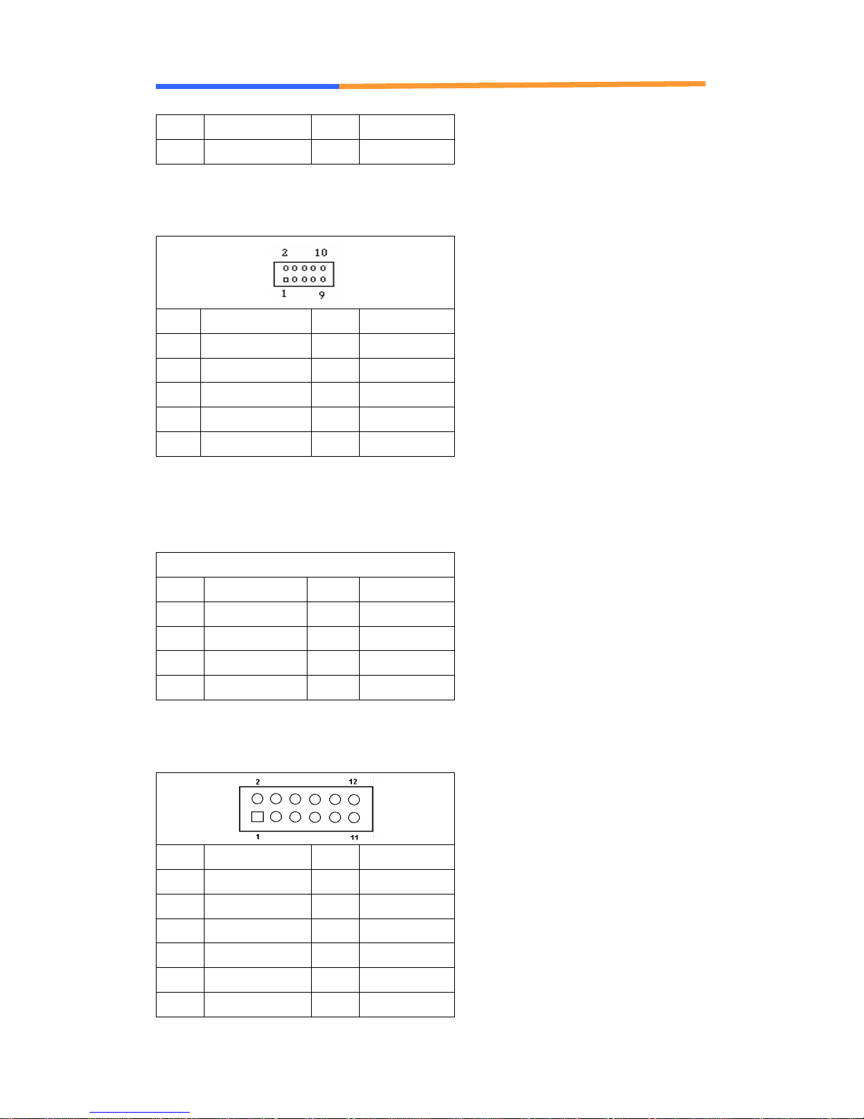
CN1/CN12: CPU/System FAN
Pin Define
1 Ground
2 +12V
3 Speed Detect
CF1 CF SLOT
WIN Enterprises, Inc. JUL., 2011
10
User ’s Manual
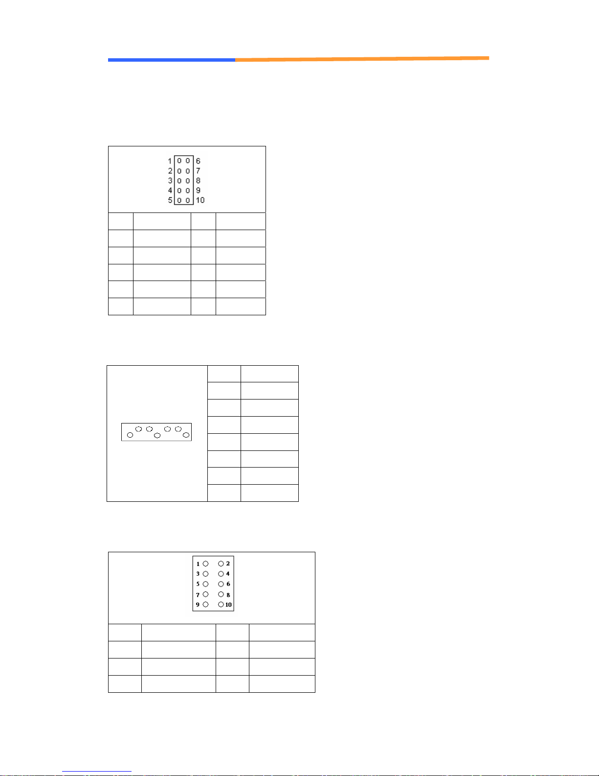
CN3: COM2 pin header
Pin Define Pin Define
1 DCD# 6 DSR#
2 RXD# 7 RTS#
3 TXD# 8 CTS#
4 DTR# 9 RI#2
5 Ground 10 NC
CN4/CN5: SATA Connector
Pin Signal
1 Ground
2 TXP
3 TXN
4 Ground
5 RXN
6 RXP
7 Ground
CN6: PS/2 KB/MS Pin Header
Pin Define Pin Define
1 KCLK 2 MCLK
3 KDAT 4 MDAT
5 N/A 6 N/A
WIN Enterprises, Inc. JUL., 2011
11
User ’s Manual
7 PS2_GND 8 PS2_GND
9 PS2_VCC 10 PS2_VCC
CN7: USB Pin Header
Pin Define Pin Define
1 +5V 2 +5V
3 USB1N 4 USB2N5 USB1P 6 USB2P
7 Ground 8 Ground
9 N/A 10 Ground
CN18/CN20:+12V Power Connector(8Pin)
Pin Define Pin Define
1 Ground 5 +12V
2 Ground 6 +12V
3 Ground 7 +12V
4 Ground 8 +12V
CN11: VGA pin header
Pin Define Pin Define
1 RED 2 GREEN
3 BLUE 4 Reserved
5 GND 6 RED RTN
7 GREEN RTN 8 BLUE RTN
9 +5V 10 GND
11 Reserved 12 SDA
WIN Enterprises, Inc. JUL., 2011
12

User ’s Manual
13 HSYNC 14 VSYNC
15 SCL 16 Reserved
CN14: LCM KEYPAD Pin Header
Pin Define
1 ACK#
2 BUSY
3 PE
4 SLCT
5 Ground
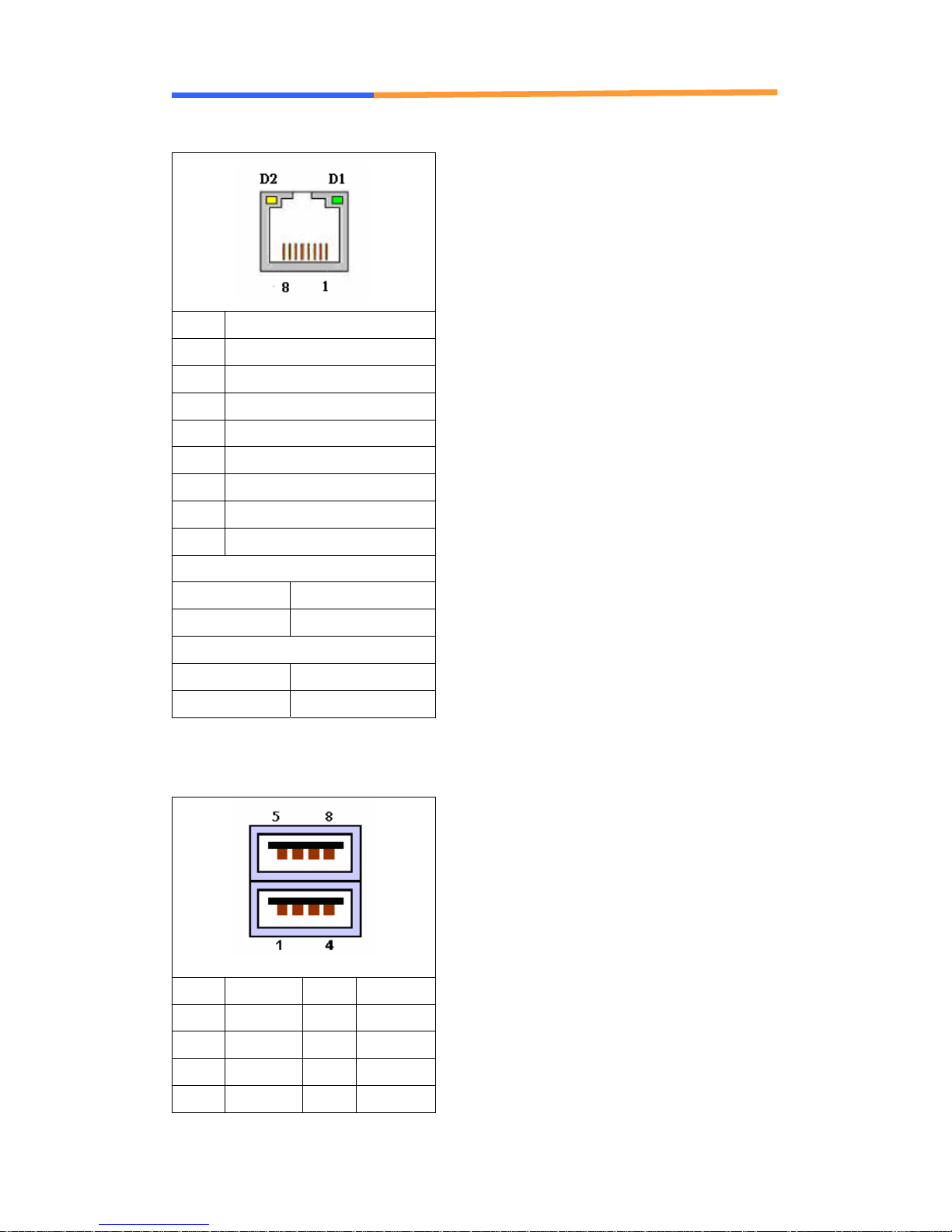
CN15: LCM Pin Header
Pin Define Pin Define
1 +5V 2 Ground
3 AFD# 4 N/A
5 INIT# 6 SLIN#
7 PD1 8 PD0
9 PD3 10 PD2
11 PD5 12 PD4
13 PD7 14 PD6
15 BLN 16 BLP
CN17:POWER pin header
Pin Define Pin Define
1 +12V 2 GND
WIN Enterprises, Inc. JUL., 2011
13
User ’s Manual
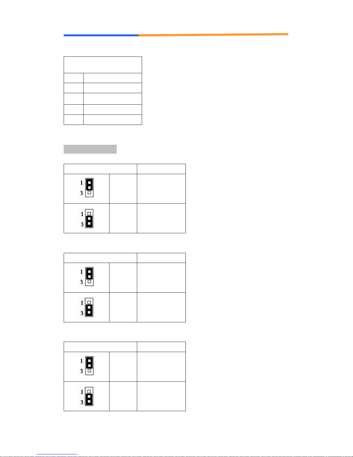
CN19/CN20/CN21/CN22/CN23/CN24: LAN RJ-45 Connector
Pin Define
1 TX+
2 TX-
3 RX+
4 Chassis Ground
5 Chassis Ground
6 RX-
7 Chassis Ground
8 Chassis Ground
D2: Speed indicated LED
1 Gbps GREEN
100 Mbps YELLOW
D1 :Link/Activity LED
Link GREEN
Activity BLINKING
CN18: USB Connector
Pin Define Pin Define
1 +5V 2 DATA0-
3 DATA0+ 4 GND
5 +5V 6 DATA1-
7 DATA1+ 8 GND
WIN Enterprises, Inc. JUL., 2011
14
User ’s Manual
PW1: HDD POWER
Pin Define
1 +12V
2 GND
3 GND
4 +5V
Jumper Settings
JP2: Clear CMOS
Pin Setting
1-2
2-3 Clear CMOS
JP4: Select Watch Dog/Bypass
Pin Setting
1-2 Watch Dog
2-3 Bypass
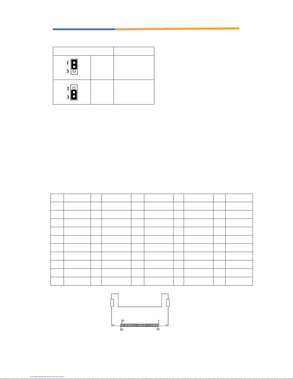
JP5: Select Bypass
Pin Setting
Normal
(Default)
WIN Enterprises, Inc. JUL., 2011
1-2 Bypass Enable
2-3 Bypass Disable
15
User ’s Manual
JP8: Select Reset/GPI
Pin Setting
1-2 GPI
2-3 RESET
2.3 CompactFlash
CompactFlash
provide complete PCMCIA-ATA functionality and compatibility plus True IDE
functionality compatible with ATA/ATAPI-4.
CompactFlash
contain no moving parts. Thus, they provide users with much greater
protection for their data than conventional magnetic disk devices.
TM
Card Socket Pin Definitions
TM
card is a small removable mass storage device. It can
TM
storage products are solid state form factors, meaning they
Pin Assignment Pin Assignment Pin Assignment Pin Assignment Pin Assignment
1 Ground 11 Ground 21 D00 31 D15 41 RESET
2 D03 12 Ground 22 D01 32 CS 42 ORDY
3 D04 13 VCC 23 D02 33 NC 43 DREG
4 D05 14 Ground 24 WP 34 IOR 44 DACK
5 D06 15 Ground 25 NC 35 IOW 45 LED
6 D07 16 Ground 26 NC 36 WE 46 BVD
7 CS 17 Ground 27 D11 37 RDY/BSY 47 D08
8 Ground 18 A02 28 D12 38 VCC 48 D09
9 Ground 19 A01 29 D13 39 SCSE 49 D10
10 Ground 20 A00 30 D14 40 NC 50 Ground
WIN Enterprises, Inc. JUL., 2011
16

User ’s Manual
Chapter 3. BIOS Setup
The ROM chip of your PL-80350 board is configured with a customized Basic
Input/Output System (BIOS) from AMI BIOS. The BIOS is a set of
permanently recorded program routines that give the system its fundamental
operational characteristics. It also tests the computer and determines how
the computer reacts to instructions that are part of programs.
The BIOS is made up of code and programs that provide the device-level
control for the major I/O devices in the system. It contains a set of routines
(called POST, for Power-On Self Test) that ch eck out the system when you turn
it on. The BIOS also includes CMOS Setup program, so no disk-based setup
program is required CMOS RAM stores information for:
z Date and time
z Memory capacity of the applia nc e
z Type of display adapter installed
z Number and type of disk drives
The CMOS memory is maintained by battery installed on the PL-80350 board.
By using the battery, all memory in CMOS can be retained when the system
power switch is turned off or there is a power outage. The system BIOS also
provides an easy way to reload the CMOS data when you replace the battery
due to battery power loss.
3.1 Quick Setup
In most cases, you can quickly configure the system by choosing the following
main menu options:
1. Choose “Exit” Î “Load Optimal Defaults” from the main menu. This loads
the setup default values from the BIOS Features Setup and Chipset
Features Setup screens.
2. Choose “Main” & “Advanced” from the main menu. This option lets you
configure the date and time, hard disk type, floppy disk drive type, primary
display and more.
3. In the main menu, press F10 (“Save Changes and Exit”) to save your
changes and reboot the system.
WIN Enterprises, Inc. JUL., 2011
17

User ’s Manual
3.2 Entering the CMOS Setup Program
Use the CMOS Setup program to modify the system parameters to reflect the
options installed in your system and to customize your system. For example,
you should run the Setup program after you:
z Received an error code at startup
z Install another disk drive
z Use your system after not having used it for a long time
z Find the original setup missing
z Replace the battery
z Change to a different type of CPU
z Run the AMI F lash program to update the system BIOS
Run the CMOS Setup program after you turn on the system. On-screen
instructions explain how to use the program.
Enter the CMOS Setup program’s main menu as follows:
1. Turn on or reboot the system. After the BIOS performs a series of
diagnostic checks, the following message appears:
“Press DEL to enter SETUP”
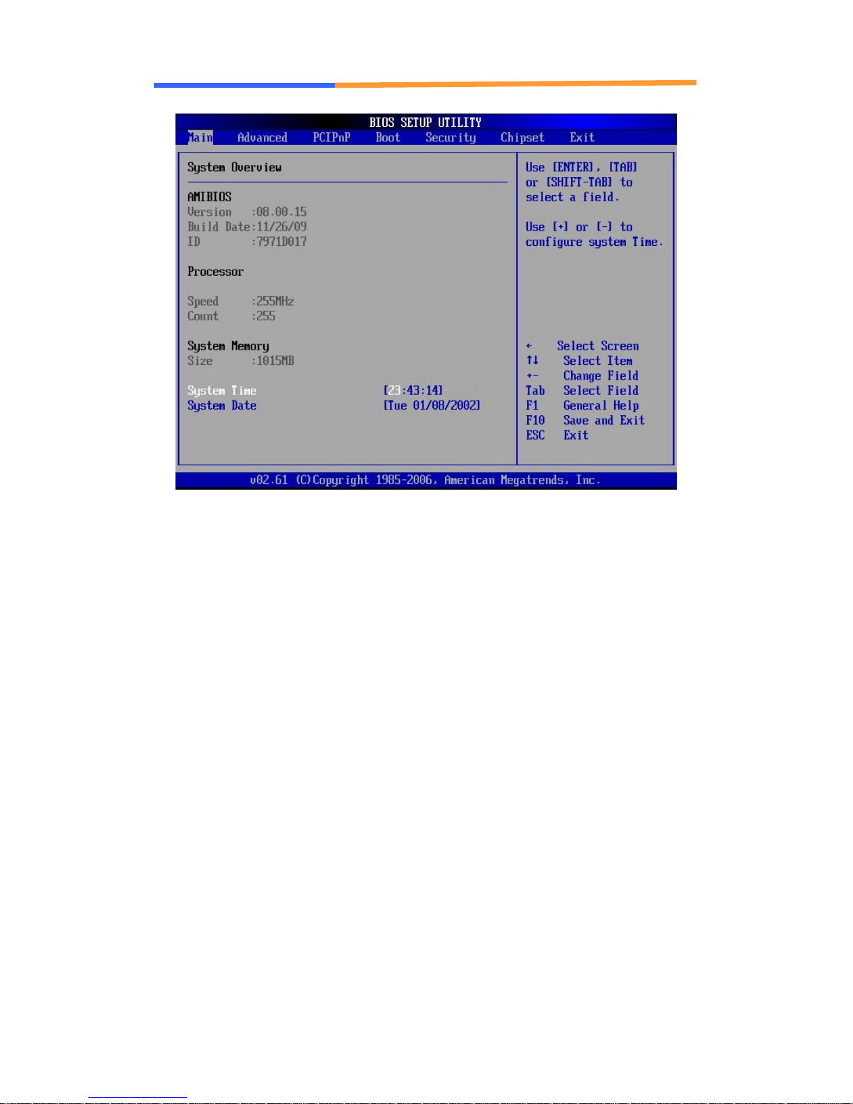
2. Press the <DEL> key to enter CMOS Setup program. The main
menu appears:
WIN Enterprises, Inc. JUL., 2011
18
User ’s Manual
3. Choose a setup option with the arrow keys and press <Enter>. See
the following sections for a brief description of each setup option.
AMIBIOS: Displays the auto-detected BIOS information.
Processor: Displays the auto-detected CPU specification.
System Memory: Displays the auto-detected system memory.
SystemTime: [hour:min:sec]:
This item allows you to set the system time.
System Date [Day mm/dd/yyyy]:
This item allows you to set the system date.
In the main menu, press F10 (“Save Changes and Exit”) to save your
changes and reboot the system. Choosing “Discard Changes and Exit”
ignores your changes and exits the pro gram. Pressing <ESC> anywhere
in the program returns you to the main menu.
WIN Enterprises, Inc. JUL., 2011
19

User ’s Manual
3.3 Menu Options
The main menu options of the CMOS Setup program are described in the
following and the following sections of this chapter.
Main: For changing the basic system configurations.
Advanced: For changing the advanced system settings.
PCIPnP: For changing the advanced PCI/PnP Settings.
Boot: For changing the system boot configurations.
Security: Use this menu to set User and Supervisor Passwords.
Chipset: For changing the chipset settings.
Exit: For selecting the exit options and loading default settings.
3.4 Advanced Menu
The Advanced menu items allow you to change the settings for the CPU and
other system devices.
Use the Advanced Setup option as follows:
1. Choose “Advanced” from the main menu. The following screen appears:
WIN Enterprises, Inc. JUL., 2011
20
 Loading...