

WIN Enterprises MB-73360 User Manual
User’s Manual
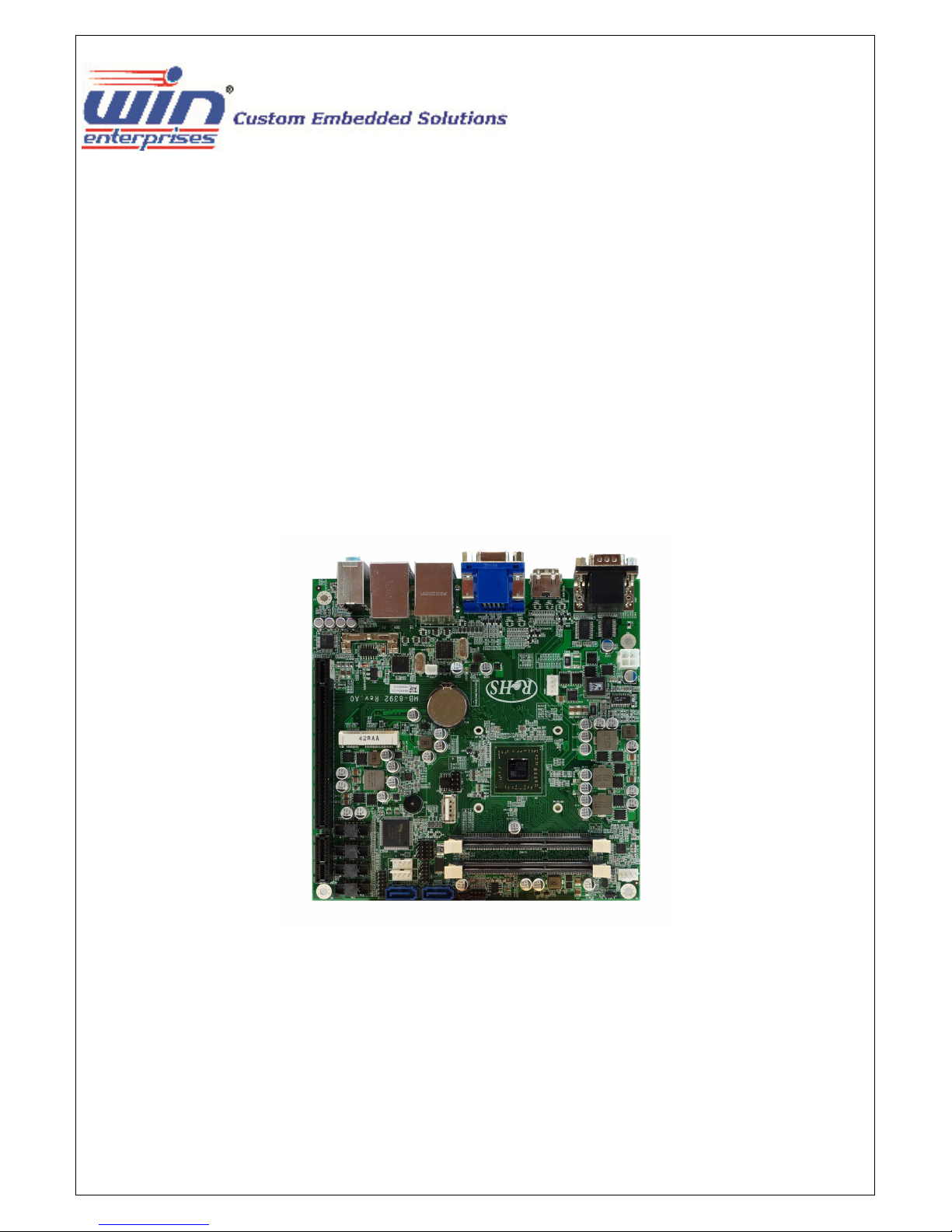
MB-73360
Mini-ITX with AMD G-series SOC (Steppe Eagle), 2 x HDMI, 1 x VGA, 2 x GLAN, 6 x
COM, 9 x USB, 2 x SATA, Mini-PCIe x 16, DC 8V ~ 32V input
WIN Enterprises, Inc. MB-73360 User’s Manual
1
Ver. Release Date Update
1.0 2015.01 Release
WIN Enterprises, Inc. MB-73360 User’s Manual
2

Copyright
Trademark
The content of this document and software with this product are copyrighted by WIN
Enterprises, Inc. This document contains proprietary information protected by
copyright. All rights are reserved; no part of this manual may be reproduced, copied,
translated or transmitted in any form or by any means without prior written permission
of the manufacturer.
The content of this document is intended to be accurate and reliable; the original
manufacturer assumes no responsibility for any inaccuracies that may be contained in
this manual. The original manufacturer reserves the right to make improvements to the
products described in this manual at any time without prior notice.
All other product names mentioned herein are used for identification purpose only and
may be trademarks and/or registered trademarks of their respective companies.
Limitation of liability
While reasonable efforts have been made to ensure the accuracy of this document,
the manufacturer and distributor assume no liability resulting from errors or omissions
in this document, or from the use of the information contained herein.
For more information on other WIN products visit our website at:
http://www.win-ent.com.
For technical support send your inquiry to sales@win-ent.com.
WIN Enterprises, Inc. MB-73360 User’s Manual
3
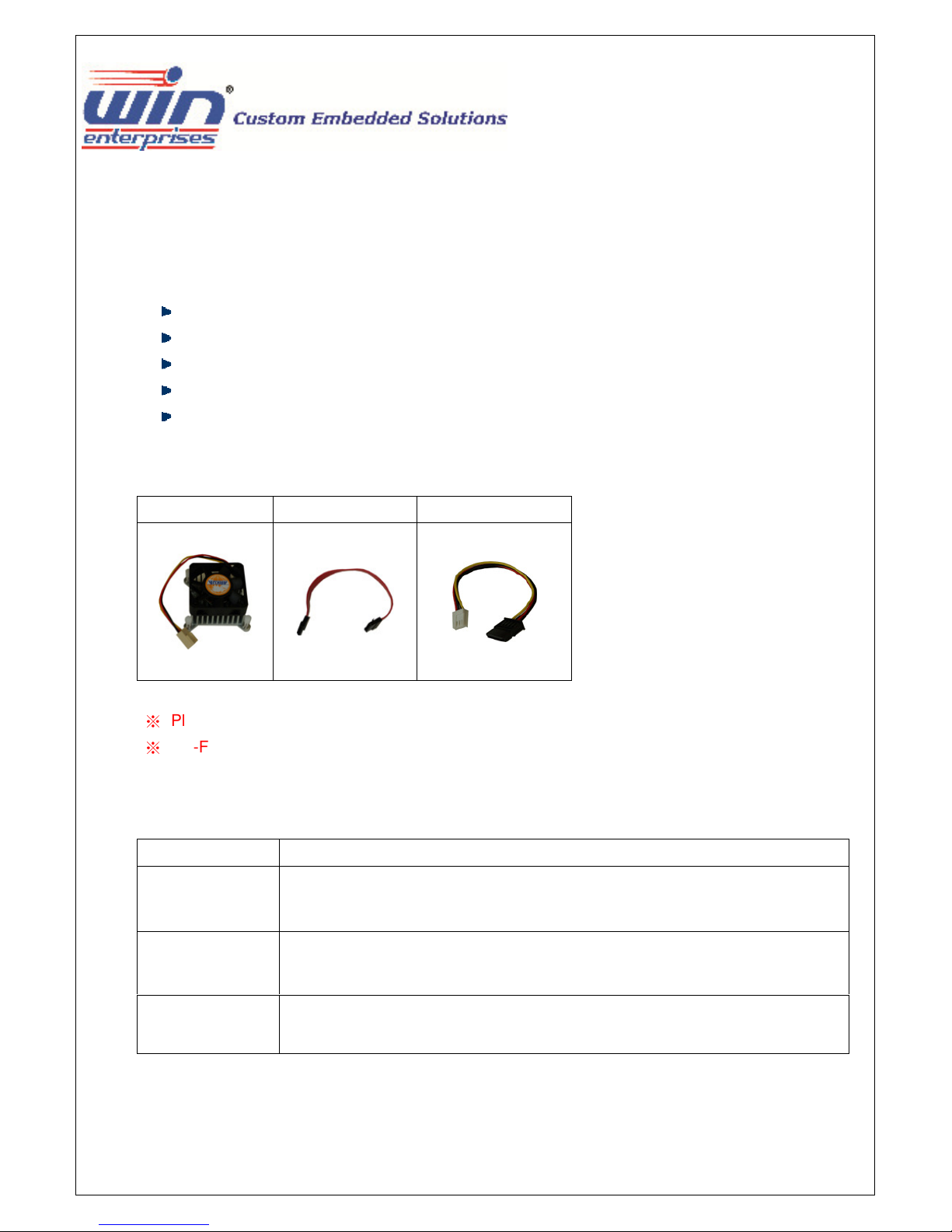
Packing list
Before using this product make sure that the following materials have been shipped:
1 x MB-73360 motherboard
1 x CPU cooler ( For 15W thermal solution )
1 x SATA cable, L/ 200mm
1 x 12V/5V SATA power cable , L/ 150mm
1 x CD Utility
*CB-F0056-00
CB-SATA11-00
CB-IPOW41-00
( P/N: CB-F00056-00 )
( P/N: CB-SATA11-00 )
( P/N: CB-IPOW41-00 )
※
Please replace CPU cooler from CB-F0056-00 to CB-F00076-00 when use MB-7336A.
※
CB-F00076-00 CPU cooler is optional and not included in the standard packing
Model Name
MB-7336A
MB-7336B
MB-7336C
* If any of those items are missing or damaged, please contact with sales representative or distributor.
Description
Mini-ITX with AMD GX-424CC SOC, DDR3 1866 up to 8GB, HDMI, VGA,
2GLAN,6 x COM, 2 x SATA, Mini-PCIe, PLIe x 16, DC 8V ~ 32V input
Mini-ITX with AMD GX-412HC SOC, DDR3 1333 up to 8GB, HDMI, VGA,
2GLAN,6 x COM, 2 x SATA, Mini-PCIe, PCIe x 16, DC 8V ~ 32V input
Mini-ITX with AMD GX-212JC SOC, DDR3 1333 up to 8GB, HDMI, VGA,2
GLAN, 6 x COM, 2 x SATA, Mini-PCIe, PCIe X16, DC 8V ~ 32V input
WIN Enterprises, Inc. MB-73360 User’s Manual
4
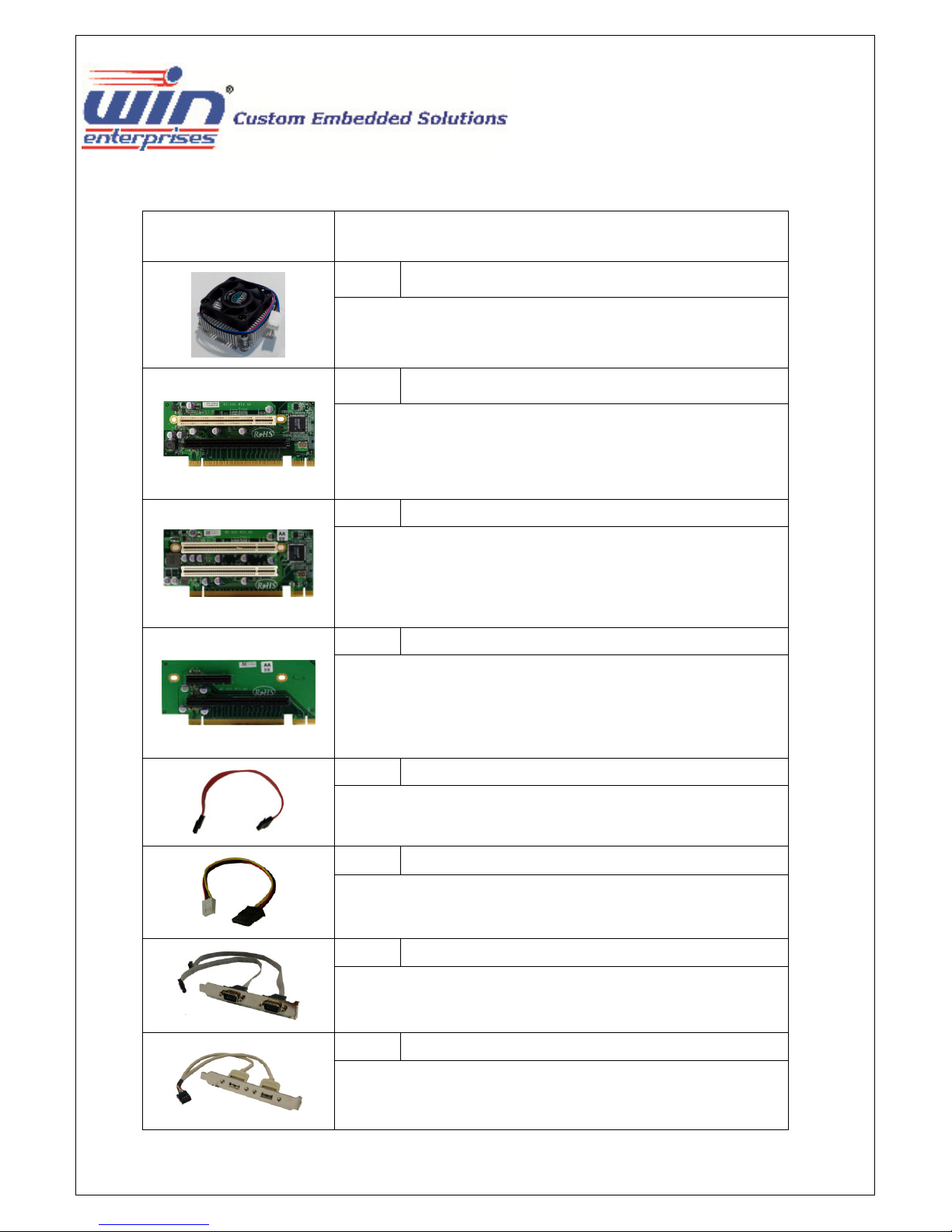
Optional Accessory :
Photo Model Name
P/N:
CB-F00076-00
CPU Cooler for high performance thermal solution
P/N:
IP-S01
PCI-express riser card support 1 x PCIe X16 & 1 x PCI slots
P/N:
IP-S02
PCI-express riser card support 2 x PCI slots
P/N:
IP-S03
PCI-express riser card support 1 x PCIe X16 & PCIe X1 slots
P/N:
CB-SATA11-00
SATA cable, L/ 200mm
P/N:
CB-IPOW41-00
12V/5V SATA power cable , L/ 150mm
P/N:
CB-ICOM38-00
Dual D-Sub 9-pin COM port card, L/ 250mm, with bracket
P/N:
Dual USB cable, L/ 250mm, with bracket
CB-IUSB07-AA
WIN Enterprises, Inc. MB-73360 User’s Manual
5

Safety Information
To prevent electrical shock hazard, disconnect the power cable from the electrical
When adding or removing devices to or from the system, ensure that the power
Before connecting or removing signal cables from the motherboard, ensure that all
Seek professional assistance before using an adapter or extension cord. These
Make sure that your power supply is set to the correct voltage in your area.
If you are not sure about the voltage of the electrical outlet you are using, contact
If the power supply is broken, do not try to fix it by yourself. Contact a qualified
outlet before relocating the system.
cables for the devices are unplugged before the signal cables are connected. If
possible, disconnect all power cables from the existing system before you add a
device.
power cables are unplugged.
devices could interrupt the grounding circuit.
your local power company.
service technician or your retailer.
Operation Safety
Before installing the motherboard and adding devices on it, carefully read all the
manuals that came with the package.
Before using the product, make sure all cables are correctly connected and the
power cables are not damaged. If you detect any damage, contact your dealer
immediately.
To avoid short circuits, keep paper clips, screws, and staples away from connectors,
slots, sockets and circuitry.
Avoid dust, humidity, and temperature extremes. Do not place the product in any
area where it may become wet.
Place the product on a stable surface.
If you encounter technical problems with the product, contact a qualified service
technician or your retailer.
WIN Enterprises, Inc. MB-73360 User’s Manual
6

Contents
1. GENERAL INFORMATION .............................................................................................................................................................. 9
1.1 I
NTRODUCTION
1.2 S
PECIFICATIONS OF BOARD
1.3 B
LOCK DIAGRAM
1.4 B
OARD LAYOUT DIMENSIONS
1.5 IO
PORTS
2. HARDWARE INSTALLATION ......................................................................................................................................................... 16
2.1 T
HE LOCATION OF ONBOARD CONNECTORS
2.2 T
HE LOCATION OF ONBOARD JUMPERS SETTING
2.3 T
HE FUNCTION LIST OF ONBOARD JUMPERS SETTING
2.3.1 JP1 : DRAM VOLTAGE SELECT ................................................................................................................................................ 20
2.3.2 JP2 : ATX & AT Power SELECT ................................................................................................................................................ 21
2.3.3 JP3 : CLEAR CMOS ................................................................................................................................................................. 22
2.4 T
HE FUNCTION LIST OF ONBOARD CONNECTORS
2.4.1 : CN1 for front Panel pin header ............................................................................................................................................. 1
2.4.2 : CN4, 9, 12, 15 for COM port pin header ............................................................................................................................. 24
2.4.3 : CN5 for Low Pin Count pin-header ...................................................................................................................................... 25
2.4.4 : CN6 & CN10 for 4-pin HDD power ...................................................................................................................................... 26
2.4.5 : CN7 for System Fan connector............................................................................................................................................ 27
2.4.6 : CN8 for 8-bit GPIO .............................................................................................................................................................. 28
2.4.7 : CN11 for PCI-Express X1 slot ............................................................................................................................................... 29
2.4.8 : CN13 & CN14 for USB ......................................................................................................................................................... 30
2.4.9 : CN17 for SPI pin header ...................................................................................................................................................... 31
2.4.10 : CN19 for Full-size Mini-PCIe socket................................................................................................................................... 32
2.4.11 : CN20 for CPU Fan connector............................................................................................................................................. 33
2.4.12 : CN21 for WLAN LED.......................................................................................................................................................... 34
2.4.13 : CN22 for 4-pin 12V power input ....................................................................................................................................... 35
2.4.14 : CN28 for Audio pin header................................................................................................................................................ 36
................................................................................................................................................................................... 9
.................................................................................................................................................................. 10
............................................................................................................................................................................... 12
............................................................................................................................................................... 13
......................................................................................................................................................................................... 14
.............................................................................................................................................. 16
....................................................................................................................................... 18
................................................................................................................................. 19
....................................................................................................................................... 23
3. BIOS MENU SETTING .................................................................................................................................................................. 37
3.1 M
AIN MENU
3.2 A
DVANCED MENU
3.2.1 PCI Subsystem Settings ........................................................................................................................................................... 1
3.2.2 ACPI Settings........................................................................................................................................................................... 1
WIN Enterprises, Inc. MB-73360 User’s Manual
.................................................................................................................................................................................... 37
............................................................................................................................................................................. 38
7

3.2.3 Trusted Computing ............................................................................................................................................................... 42
3.2.4 CPU Configuration ................................................................................................................................................................ 43
3.2.4.1 CPU Information ................................................................................................................................................................ 44
3.2.5 IDE Configuration.................................................................................................................................................................... 1
3.2.6 USB Configuration .................................................................................................................................................................. 1
3.2.7 Platform Function ................................................................................................................................................................... 1
3.2.8 F81866 Super IO Configuration............................................................................................................................................... 1
3.2.8.1 Serial Port 0, 1, 2, 3, 4, 5 Configuration............................................................................................................................. 49
3.2.9 F81866 H/W Monitor............................................................................................................................................................ 50
3.2.9.1 Smart Fan Mode Configuration ......................................................................................................................................... 51
3.2.10 Serial Port Console Redirection ........................................................................................................................................... 52
3.2.10.1 COM0, COM1 Setting....................................................................................................................................................... 53
3.3 C
HIPSET MENU
3.3.1 South Bridge ......................................................................................................................................................................... 55
3.3.1.1 SB SATA Configuration ......................................................................................................................................................... 1
3.3.1.2 SB USB Configuration........................................................................................................................................................... 1
3.3.2 North Bridge Configuration .................................................................................................................................................. 58
3.4 B
OOT MENU
3.4.1 CSM16 Parameters ................................................................................................................................................................. 1
3.5 S
ECURITY MENU
3.6 S
AVE & EXIT MENU
................................................................................................................................................................................. 54
.................................................................................................................................................................................... 59
............................................................................................................................................................................... 62
............................................................................................................................................................................. 1
4. DESIGN RESOURCES................................................................................................................................................................. 64
4.1 S
YSTEM RESOURCES
........................................................................................................................................................................... 64
WIN Enterprises, Inc. MB-73360 User’s Manual
8

1. General Information
1.1 Introduction
MB-73360 is a Mini-ITX motherboard support AMD® Embedded G-series SOC (Steppe Eagle) with
AMD Radeon™ HD series Graphics. Integrated graphics include 2 x HDMI + 1 x VGA port, Two DDR3
SO-DIMM supports a maximum of 16GB DDR3 1600 of system memory.
On the I/O ports, the MB-73360 provides plenty of connectivity with 2 x Intel® i211AT GbE LAN
controller, 6 x RS232, 2 x USB3.0 + 7 x USB2.0, HD Audio, 2 x SATA, 8-bit GPIO, optional TPM 1.2
function. The MB-73360 accepts a wide range 8V ~ 32V DC input suitable for a variety of applications
in digital signage, POS, kiosks and gaming.
Besides standard PCIe X16 and Mini-PCIe socket, WIN’s Mini-ITX delivers flexible PCIe X1 expansion
slot allowing customers to install WIN’s riser card for an additional 1 ~ 3 PCIe + PCI slots for various
application.
WIN has its own firmware team that could provide customize BIOS service, such as security boot
function for gaming application……..
About WIN Enteprises. Inc.
WIN offers reliable and solid products which are produced under Management System Standards:
ISO9001-2000 Certificate. The certificate keeps us focused on our quality objectives of management
and environmental production. Its willingness to customize standard products for meet unique customer
needs makes WIN different. All ODM projects are welcome. Years of experiences enables WIN to fulfill
the customer’s vision, by delivering products to exact specifications. WIN R&D team is proud of its
strong engineering background. R&D professionals account for 25% of the AEWIN workforce. We
focus on developing new products for both emerging and established markets.
For more information about an OEM/ODM relationship contact us at:
Email: sales@win-ent.com TEL: +1 (978) 688-000
WIN Enterprises, Inc. MB-73360 User’s Manual
9
External : 2 x USB3.0 ( compatible with USB 2.0 ) + 2 x USB2.0
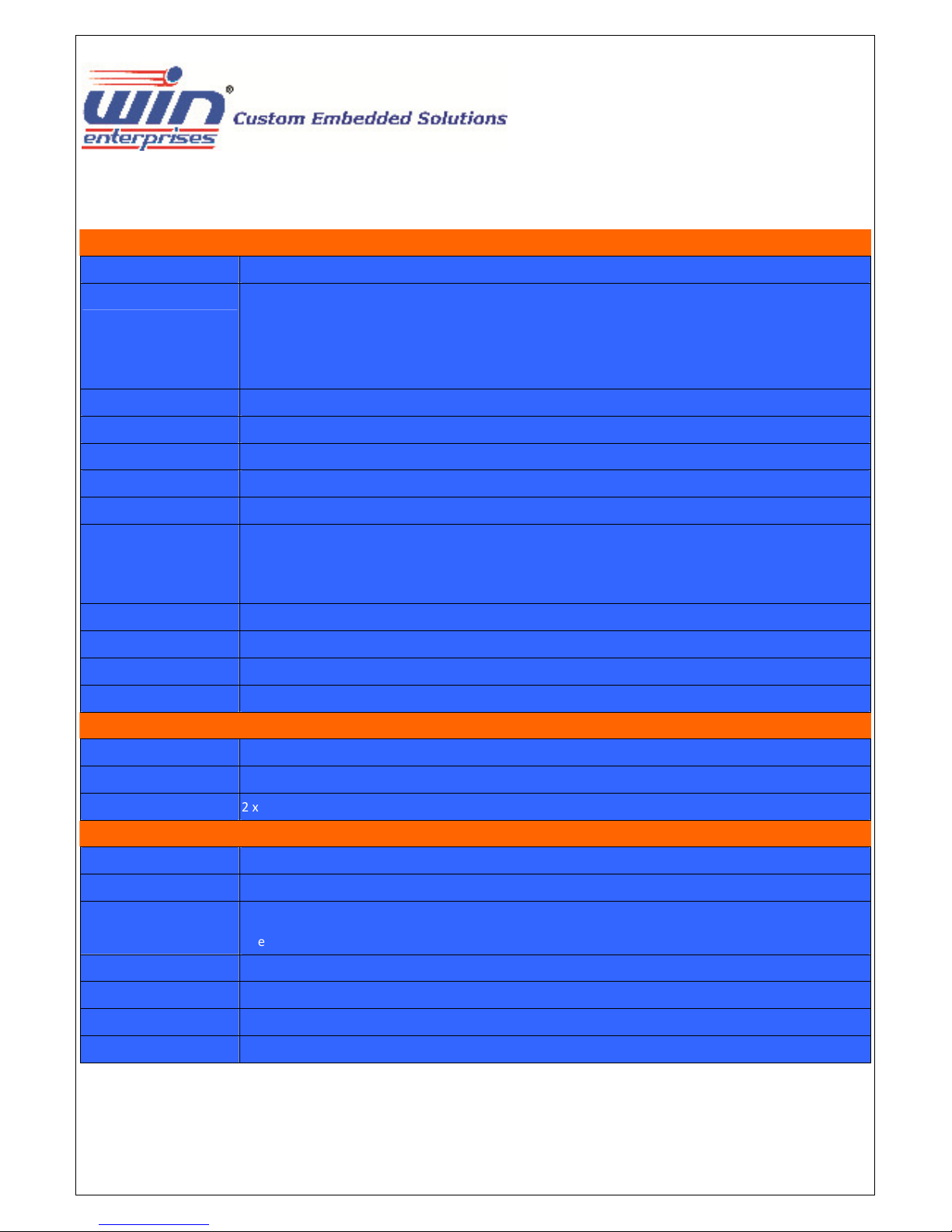
1.2 Specifications
System
From Factor Mini-ITX
CPU AMD Embedded G-series SOC / STEPPE EAGLE
MB-7336A: AMD GX-424CC, Quad Core 2.4GHz , 25W TDP ( DDR3-1866 )
MB-7336B: AMD GX-412HC, Quad Core 1.2GHz , 7W TDP ( DDR3-1333 )
MB-7336C : AMD GX-212JC, Dual Core 1.2GHz , 6W TDP ( DDR3-1333 )
Chipset Integrated
Memory 2 x DDR3 SO-DIMM / 1866 MHz up to 8GB, w/o ECC support
BIOS AMI SPI BIOS
SSD None
Watchdog timer 255 levels, 1 ~ 255 sec
Expansion 1 x Full-size Mini-PCIe socket With PCIe X1 & USB signal.
1 x PCI Express X16 slot ( Support PCIe X4 signal )
1 x PCI Express X1 slot ( Optional )
Board Size 170mm x 170mm
Operating Temp. 0°C~60°C (32°F~140°F)
Storage Temp. .-20°C~80°C (-4°F~176°F)
Operating Hum. 10%~90% (non-condensing)
Display
Chipset AMD G-series SoC integrated
Display interface 1 x external VGA
2 x external HDMI 1.4 w/ lockable connector. ( Support up to 4k*2k )
I/O
Series Port Internal : 4 x RS232 , External 2 x RS232
SATA 2 x SATAIII-600
USB
Internal : 4 x USB2.0 ( Pin header ) , 1 x USB2.0 connector
Ethernet External : 2 x Intel I211AT Gigabit Ethernet ( Support Wake On LAN )
Audio External : Line-in/out , Mic-in
Digital I/O Internal : 8-bit GPIO interface
LPC 1 x LPC header for Optional TPM module
WIN Enterprises, Inc. MB-73360 User’s Manual
10
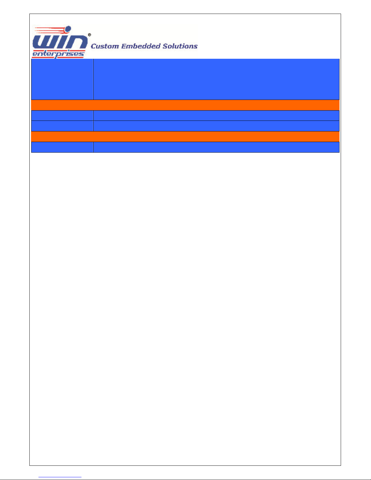
PU cooling Fan header, 1 x System cooling Fan header
C out for SATA HDD
Others 1 x C
1 x Front Panel header for power on/off, reset, HDD/power LED indicator
2 x 4-pin 12V/5V D
1 x 2-pin for Mini-PCIe LED indicator
Power
Power in DC 8V ~ 32V input ( AT/ATX mode jumper selectable )
Power connector 1 x 4-pin internal header ( Molex 4-pin )
Certification
Certification CE , FCC Class B
Note : All specifications and photos are subject to change without notice.
WIN Enterprises, Inc. MB-73360 User’s Manual
11

1.3 Block Diagram
2 x Intel i211AT GLAN
Full-Size Mini-PCIe socket
2 x Internal USB 2.0
( Pin header )
2 x External USB 2.0
1 x Internal USB 2.0
(Connector)
PCI Express X16 slot
(Support PCIe X4 signal )
2 x SATAIII
2 x External USB 3.0/2.0
PCIe
PCIe
USB2.0
USB 2.0
PCIe X4
SATA
USB3.0
GX424 / QC 2.4G
GX412 / QC 1.2G
GX212 / DC 1.2G
2 x DP
1 x VGA
1 x PCIe X4
4 x PCIe X1
2 x SATA
2 x USB3.0
8 x USB2.0
1 x SD
1 x LPC
1 x SPI
DP1
VGA
HDA
HDMI 1.4a
HDMI 1.4a
1 x DB15 VGA
Audio
LPC header (TPM)
F81866
6 x RS232
( 2x External
4x Internal )
8-bit GPIO
BIOS
WIN Enterprises, Inc. MB-73360 User’s Manual
SPI
WDT, H/W Monitor
12
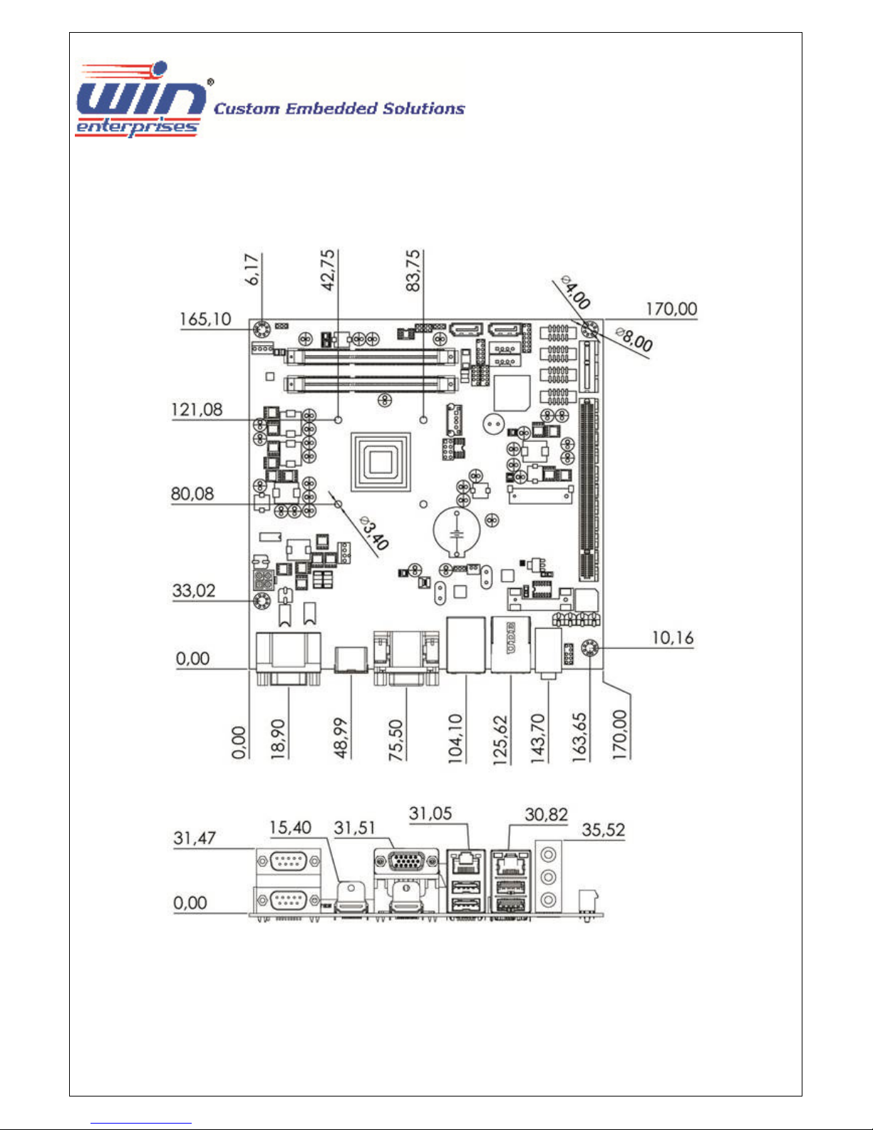
1.4 Board Layout Dimensions
WIN Enterprises, Inc. MB-73360 User’s Manual
13
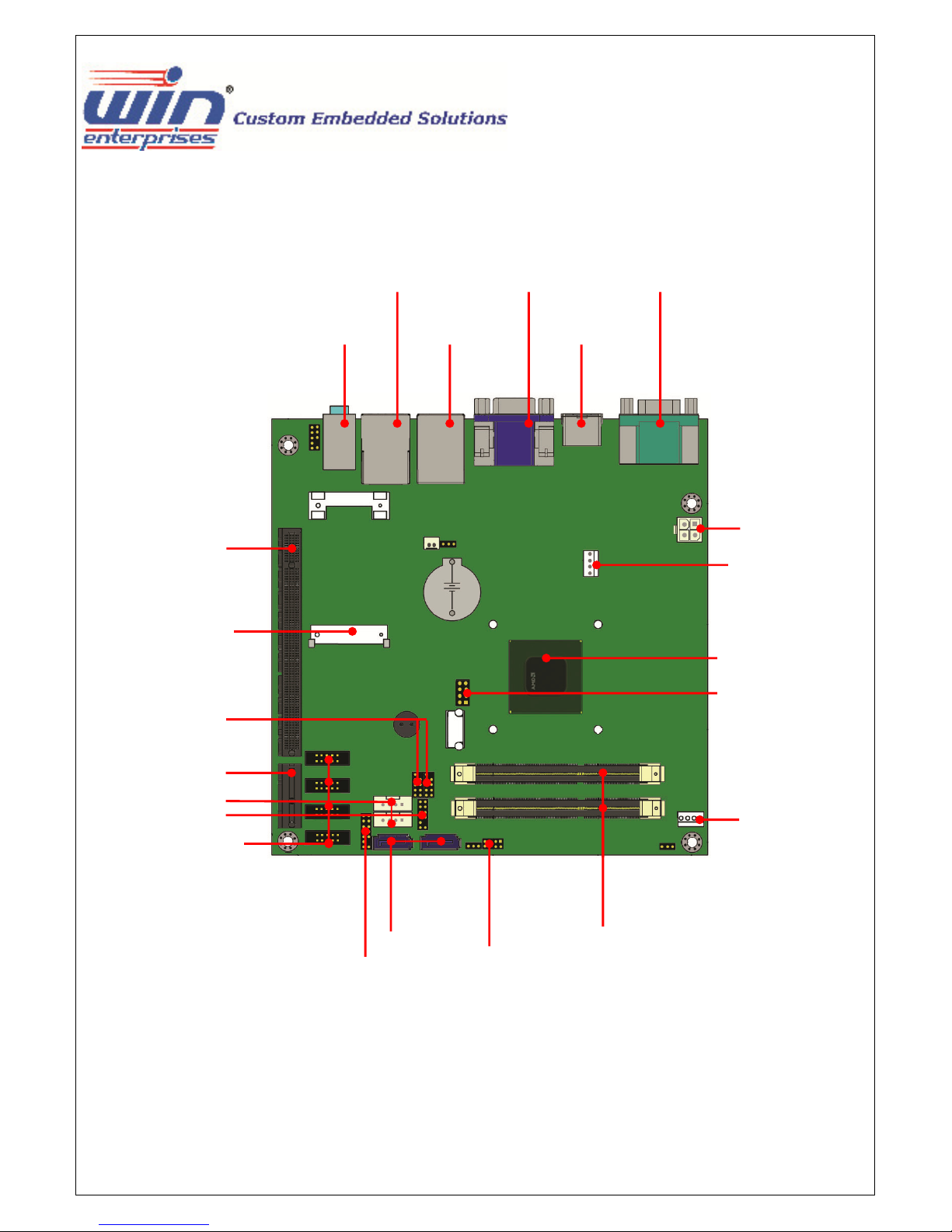
1.5 IO ports
PCI-E X16 slot
Full-size Mini-PCIe
USB pin header
PCI-E X1 slot
(Optional)
SATA power
GPIO
4 x COM
GLAN + USB2.0
Audio
LPC
GLAN + USB3.0
SATA3
VGA + HDMI
Front Panel
Dual COM
HDMI
DDR3 SO-DIMM
DC 8V ~ 32V In
CPU Fan
AMD® G-series SOC
SPI connector
System Fan
WIN Enterprises, Inc. MB-73360 User’s Manual
14
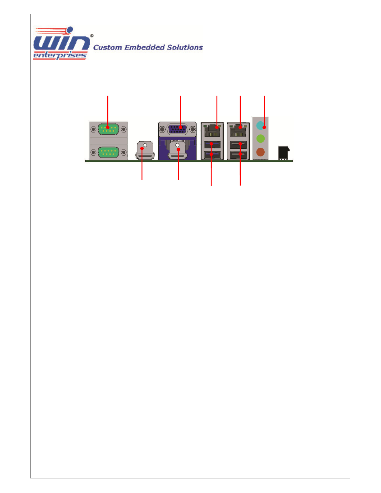
Dual COM VGA GLAN GLAN Audio
HDMI HDMI
USB3.0 USB2.0
WIN Enterprises, Inc. MB-73360 User’s Manual
15
2. Hardware installation
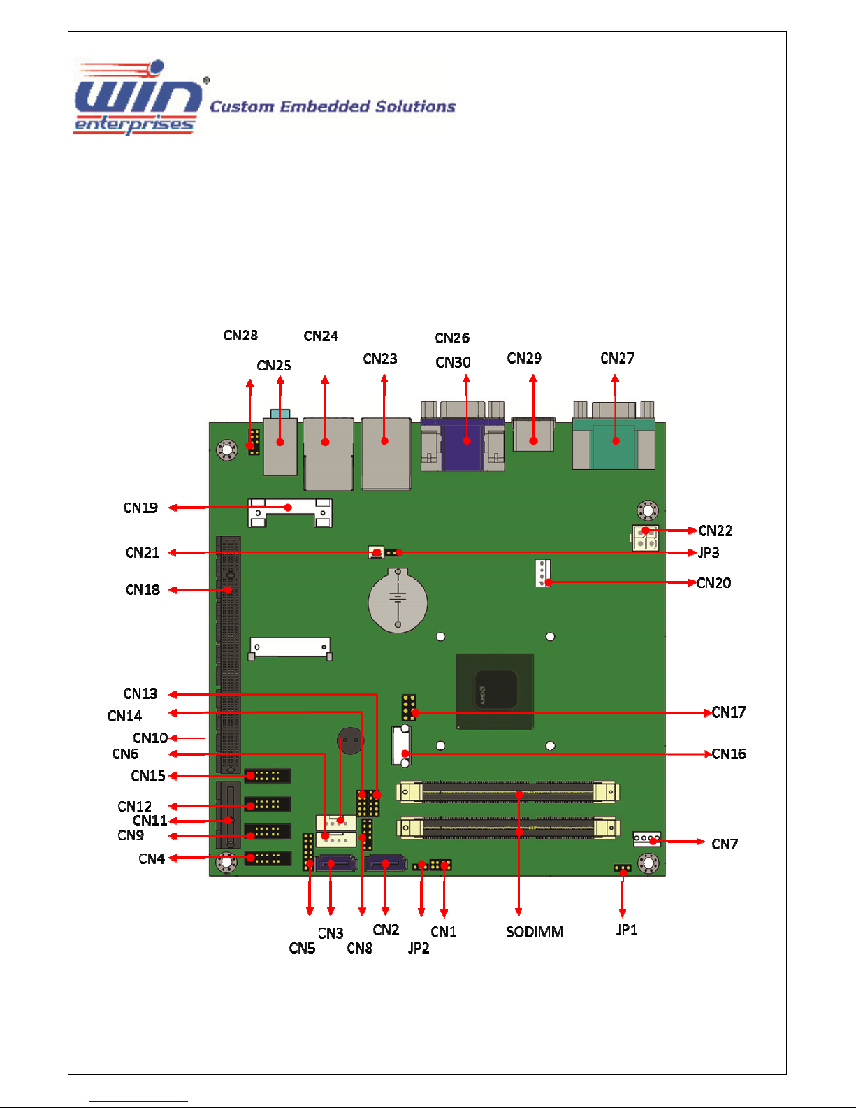
2.1 The location of onboard connectors
WIN Enterprises, Inc. MB-73360 User’s Manual
16

CN1 FRONT PANEL
CN2 SATA1
CN3 SATA0
CN4 COM4
CN5 LPC
CN6 HDD POWER CONN.
CN7 SYSTEM FAN
CN8 GPIO
CN9 COM3
CN10 HDD POWER CONN.
CN11 PCIE X1 SLOT
CN12 COM5
CN13 USB 3,4
CN14 USB 1,2
CN15 COM6
CN16 USB 5
CN17 SPI
CN18 PCIE X16 SLOT
CN19 MINI PCIE
CN20 CPU FAN
CN21 WLAN LED
CN22 DC IN
CN23 LAN0 + USB 3.0
CN24 LAN1 + USB 2.0
CN25 AUDIO
CN26 VGA
CN27 COM 1/2
CN28 AUDIO FRONT HEADER
CN29 HDMI 1
CN32 HDMI 0
WIN Enterprises, Inc. MB-73360 User’s Manual
17
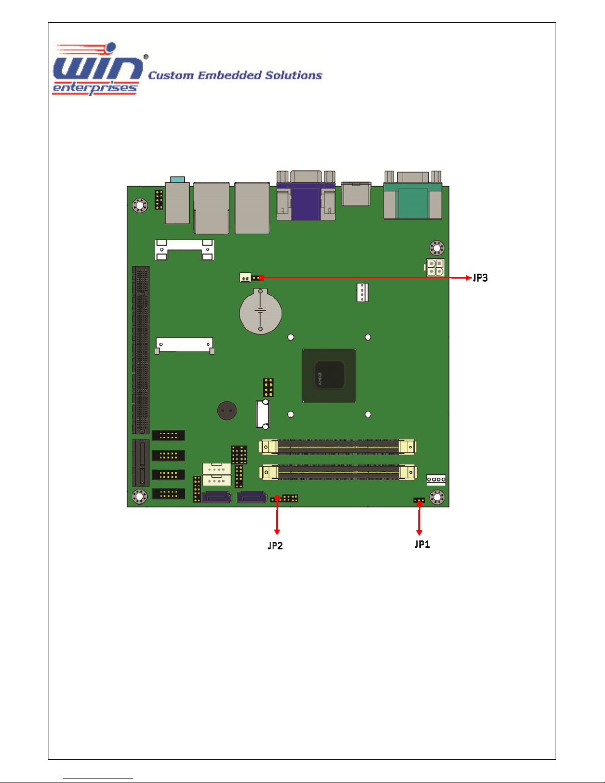
2.2 Location of onboard jumper settings
WIN Enterprises, Inc. MB-73360 User’s Manual
18

2.3 Function list of onboard jumpers setting
JP1 DRAM VOLTAGE SELECT
(1-2: 1.5V ; 2-3: 1.35V)
JP2 ATX & AT Power SELECT
(1-2: AT ; 2-3: ATX)
JP3 CLEAR CMOS
(1-2 FOR NORMAL ; 2-3 FOR CLEAR CMOS)
WIN Enterprises, Inc. MB-73360 User’s Manual
19
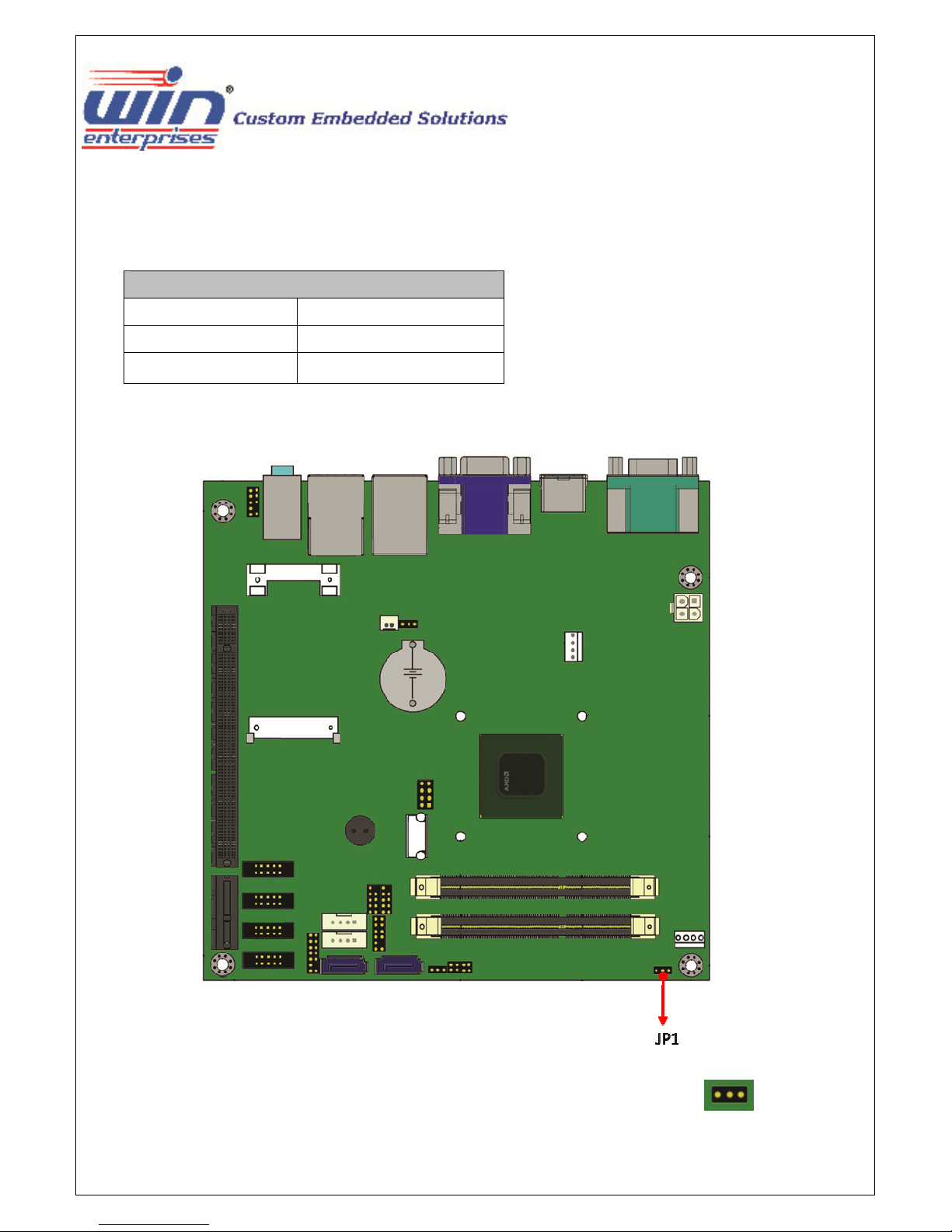
2.3.1 JP1: DRAM VOLTAGE SELECT
JP1
Closed Pin Result
1-2 1.5V
2-3 * 1.35V
* Default setting
WIN Enterprises, Inc. MB-73360 User’s Manual
3 1
20
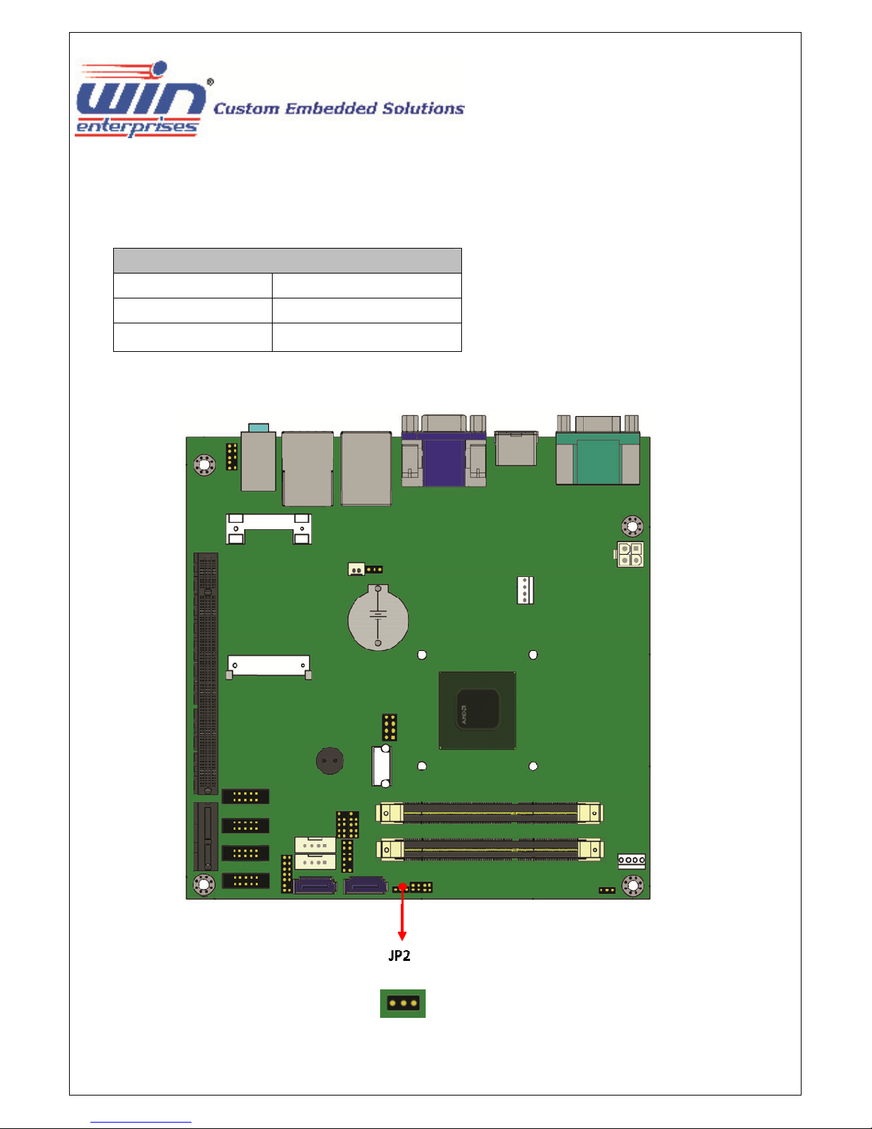
2.3.2 JP2: ATX & AT Power SELECT
JP2
Closed Pin Result
1-2
2-3 *
AT
ATX
* Default setting
WIN Enterprises, Inc. MB-73360 User’s Manual
3 1
21
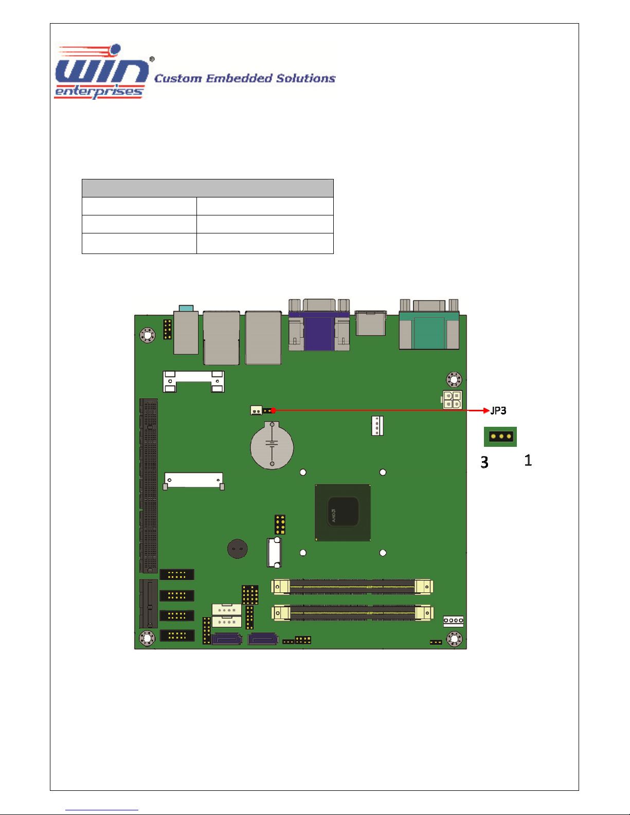
2.3.3 JP3: CLEAR CMOS
JP3
Closed Pin Result
1-2*
2-3
* Default setting
FOR NORMAL
FOR CLEAR CMOS
WIN Enterprises, Inc. MB-73360 User’s Manual
22
 Loading...