

WIN Enterprises MB-63000 Installation Manual
1
Installation guide
Version 1.0.1
Model: MB-63000
Gaming Control board powered by AMD® S1 Socket CPU with RS690E
chipset, I/O and security
sales@win-ent.com (978) 688-2000

2
Table of Contents.................................................................................................. 2
Chapter 1 General Information........................................................................... 3
1-1 Introduction..................................................................................................... 3
1-2 Specification................................................................................................... 4
1-3 Packaging............................................................................................. 6
Chapter 2 Connectors and Jumper Setting.................................................... 9
2-1 List of Connectors......................................................................................... 9
2-2 Location of Connectors............................................................................... 10
2-3 List of Jumpers............................................................................................. 11
2-4 Location of Jumpers................................................................................... 12
Chapter 3 BIOS setting........................................................................................ 28
3-1 Enter BIOS Setup......................................................................................... 28
3-2 Main................................................................................................................ 29
3-3 Advanced Settings...................................................................................... 30
3-4 Advanced PCI/PnP Settings...................................................................... 37
3-5 Boot Settings................................................................................................ 39
3-6 Security Settings......................................................................................... 41
3-7 Advanced Chipset Settings....................................................................... 42
3-8 Power Setting............................................................................................... 46
3-9 Exit.................................................................................................................. 47

3
Chapter 1 General Information
1-1 Introduction
The MB-63000 Gaming Control board is based on AMD S1 Socket architecture and supports a 1.0 to
2.0GHz Turion/Mobile Sempron CPU. It offers a wide range of price/performance for gaming
applications. The ATI Radeon X700-based DirectX 9.0 graphic engine supports dual displays with
2D/3D and motion video acceleration. Plus the on-board 15W x2 Class-D stereo audio amplifier, the
MB-63000 would perform kinds attractive content for gaming and amusement machine applications.
The MB-63000 has TPM 1.2, FPGA, AeSecur™ and Customized BIOS, whose security circuits
protect gaming programs and/or media content. On-board DDR II system memory provides a highly
stable working environment. And SO-DIMM DDRII slot enables extended capability. NVRAM/FRAM
and an Intrusion detection circuit provide event log recording even when unplugged.
Up to a total of 96 digital I/O serves all kinds gaming and amusement applications, this includes 40
photo-couple isolated inputs, 24 sink outputs with 500mA current, 4 sink outputs with 1A current, 4
MOSFET sink outputs with 30V/2A current, 8 source outputs with 500mA current, and 16 spared bidirectional general purpose I/O.
There are two STAT connectors, one IDE connector, one CompactFlash™ Type II socket and onboard NANDrive for mass storage selection. Other features include one or two Gigabit Ethernet
interface, PCI expansion slot, 4 timers and an optional iButton socket.
The MB-63000 is the best choice for video slot machines (Class II/III), Video lottery terminals,
Amusement game machines, Master unit of roulette machine, Downloadable gaming terminals, highend vending machines, as well as ATMs/Cash machines and Kiosks.
4
1-2 Specifications
System
CPU
AMD® Turion/Mobile Sempron S1 Socket CPU 1.0 to 2.0GHz
Fanless operation available
BIOS Award® 512KB Flash BIOS
Chipset AMD® / ATI M690E + SB690 chipsets
System Memory
Onboard 2 banks 512MB DDRII memory
One SO-DIMM DDRII 400/533/667MHz up to 1GB w/o ECC
Display
Video Chipset
AMD®/ATI M690E with ATI Radeon™ X700 based DirectX 9.0 2D/3D graphic engine
2D Acceleration Features:
- Highly optimized 128-bit engine, capable of processing multiple pixels per clock
- Supports a maximum resolution of 2560 x 1600
- Game acceleration including support for Microsoft's DirectDraw
3D Acceleration Features:
- Full DirectX 9.0 support
- 3D texture support, including projective 3D textures
- Anti-Aliasing using multi-sampling algorithm with support for two, four, and six samples
- New generation rendering engine provides outstanding 3D performance
- Support for OpenGL format for Indirect Vertices in Vertex Walker
Motion Video Acceleration Features:
- MPEG2 (MP@ML) hardware standard definition decode acceleration support
- WMV9 hardware standard definition decode acceleration support
- True 10-bit color processing renders up to 1.07billion colors
- Automatic Gain Control for the right brightness balance through ATI Avivo™ technology
- 3D comb filtering to minimize color bleeding through ATI Avivo™ technology
- Video post-processing hardware for de-interlacing, bob, clipping, and padding
- 3:2 pull-down for conversion of video to film
Video Interface
Primary - Analog RGB
Secondly - DVI or dual channel LVDS 24-bit
Audio
Audio Chipset AC 97
Power amp. Onboard 15W x 2 Class-D stereo power amplifier
Audio Interface 1 x Mic in, 1 x Line in , 1 x Audio out, 2 x Speaker out
Ethernet
Ethernet Chipset
Intel® 82573L 10/100/1000Base-TX Ethernet
Full duplex operation
Wake-on LAN capacity
Ethernet Interface 2 x RJ-45
Storage
CF card
One CF type I/II or
Onboard 128 ~ 4GB solid state disk (manufacture option)
HDD
One E-ATA connector
Two SATA connectors
Security
Security
8-pin, Serial EEPROM for storage of serial numbers, data, security keys
TPM 1.2 on LPC; aeSecure™ (onboard USB)
Watchdog Timer Programmable watchdog timer, time-out value up to 256sec
FPGA (optional)
ROM 2MB Flash ROM onboard (PCI, Bootable)
NVRAM
Onboard 1MB (2 banks 512KB) FRAM/NVRAM
Optional 4MB FRAM/NVRAM removable module
5
Security
(optional)
iButton socket on backplane or cabinet (through spared GPIO)
Timers 4 x programmable timer with timeout interrupt implement by FPGA
Intrusion Detection
By battery powered single chip microcontroller
Operates with and without system active
6 x Intrusion detection input
Logs date/ time of last 32 events
Events include door status, system resets/brownouts
On-chip EEPROM backup
12C Optional by FPGA (through spared GPIO)
Digital gaming I/O
3 x 50-pin Box Header include
- 40 x photo-couple isolated input
- 24 x 500mA current sink output
- 4 x 1A current sink input
- 4 x MOSFET 30V/1A current sink output
- 8 x 500mA current source output
- 16 x spared general purpose I/O
Expansion
Expansion Slot One PCI slot
I/O Connector
I/O Connectors
3 x RS-232 D-SUB9
1 x RS-232/422/485 D-SUB9, jumper selectable
2 x CCTalk/TTL (I/O box header)
4 x USB2.0
5 x USB2.0 (pin header)
1 x IrDA Tx/Rx (pin header)
1 x PS2 KB/MS (pin header)
1 x Parallel port ( pin header)
Power Supply
Voltage
Single DC +12V power input for logics;
Separated DC +5/+12V/+24V power input for gaming I/O
Software
O/S
Windows XP Embedded; Linux (optional)
Mechanical and Environmental
System Health
Monitoring
Measurement of CPU core and system temperature with thermal trip.
Speed monitoring for CPU fan and two system fans
Environmental
Operating Temperature: 0 ~ 60°C (32 ~ 140°F)
Storage Temperature: -20 ~ 85°C (-4 ~ -185°F)
Relative Humidity: 10 ~ 90% RH, non-condensing
Approval
FCC/CE Class A
RoHS, WEEE
Dimension ( L x W
)
295mm (L) x 220mm(W) (11.6"L x 8.7"W )
Ordering information
MB-6300A
Enclosed gaming platform powered by AMD® S1 Socket CPU with RS690 chipset, I/O
and security
Appliance Level
PL-63000
Enclosed platform powered by AMD® S1 Socket CPU with RS690 chipset, I/O and
security
Optional
Optional Board I/O backplane ( customize optional)
R-106A Riser card with one PCI slot
R-107A 4MB FRAM module
R-107B 4MB NVRAM module

6
1-3 Packaging
Please make sure that the following items have been included in the package before installation.
MB-63000 Gaming Control board
Quick Installation Guide
CD-ROM containing the following folders:
• Manual (in PDF format)
• Windows XP Embedded drivers
• AMD * Authenex
• Intel Network Driver
• Realtek Audio Driver
• TPM Host Software
• FPGA Driver
*Note: Microsoft .NET 2.0 or later is required for AMD Catalyst Control Panel Driver applications.
You must install .NET before installing the driver.
If any of these items are missing or damaged, please contact your dealer from whom you purchased
the board at once. Save the shipping materials and carton in the event that you want to ship or store
the board. After you unpack the board, inspect it to assure an intact shipment. Press down all the
integrated circuits to make sure they are properly seated. Do not apply power to the board if it
appears damaged.
Leave the board in its original packing until you are ready to install
Precautions
Make sure you properly ground yourself before handling the board or other system
components. Electrostatic discharge can damage the board.
Do not remove the anti-static packing until you are ready to install the board.
Ground yourself before removing any system component from it protective anti-static
packaging. To ground yourself, grasp the expansion slot covers or other unpainted parts of
the computer chassis.
Handle the board by its edges and avoid touching its component.
7
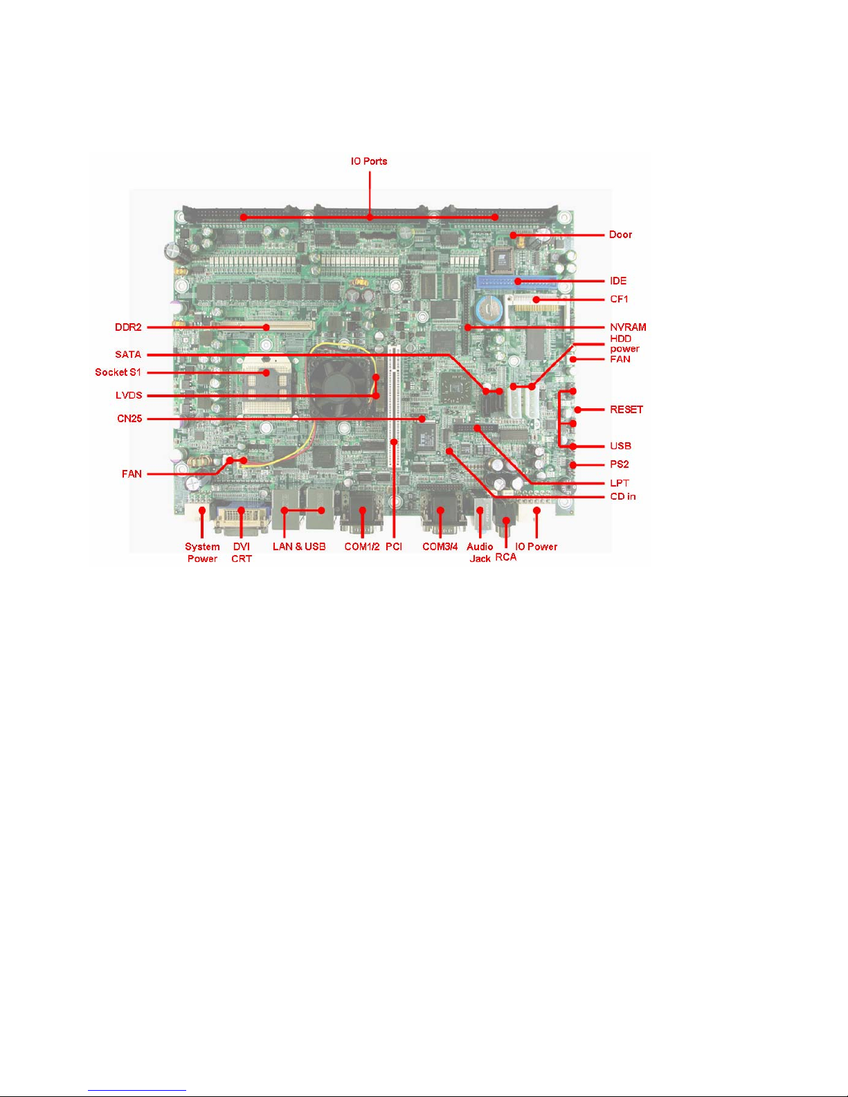
1-4 Board Layout
Board
Layout
(Component
Side)
8
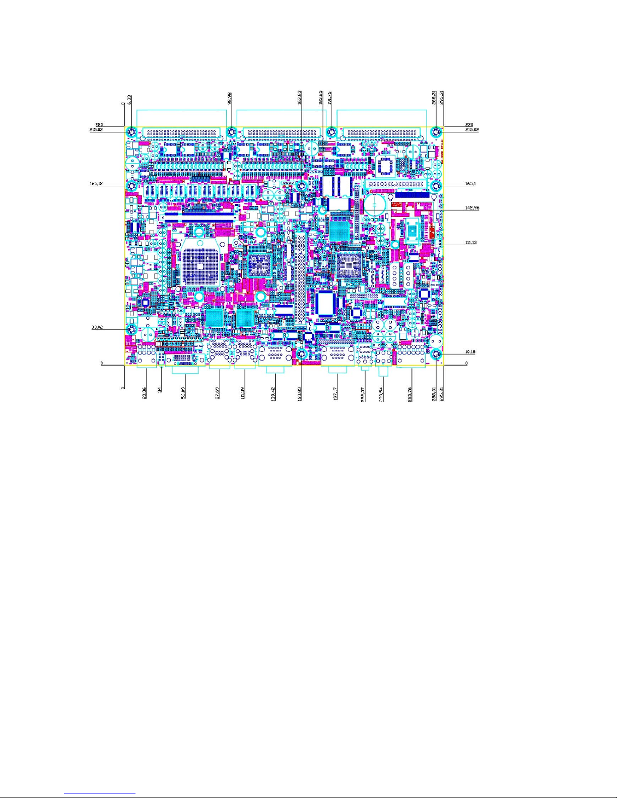
1-5 Board Dimensions
Board Dimension (mm) (Component Side)
9
Chapter 2 Connectors and Jumper Settings
2-1 List of Connectors
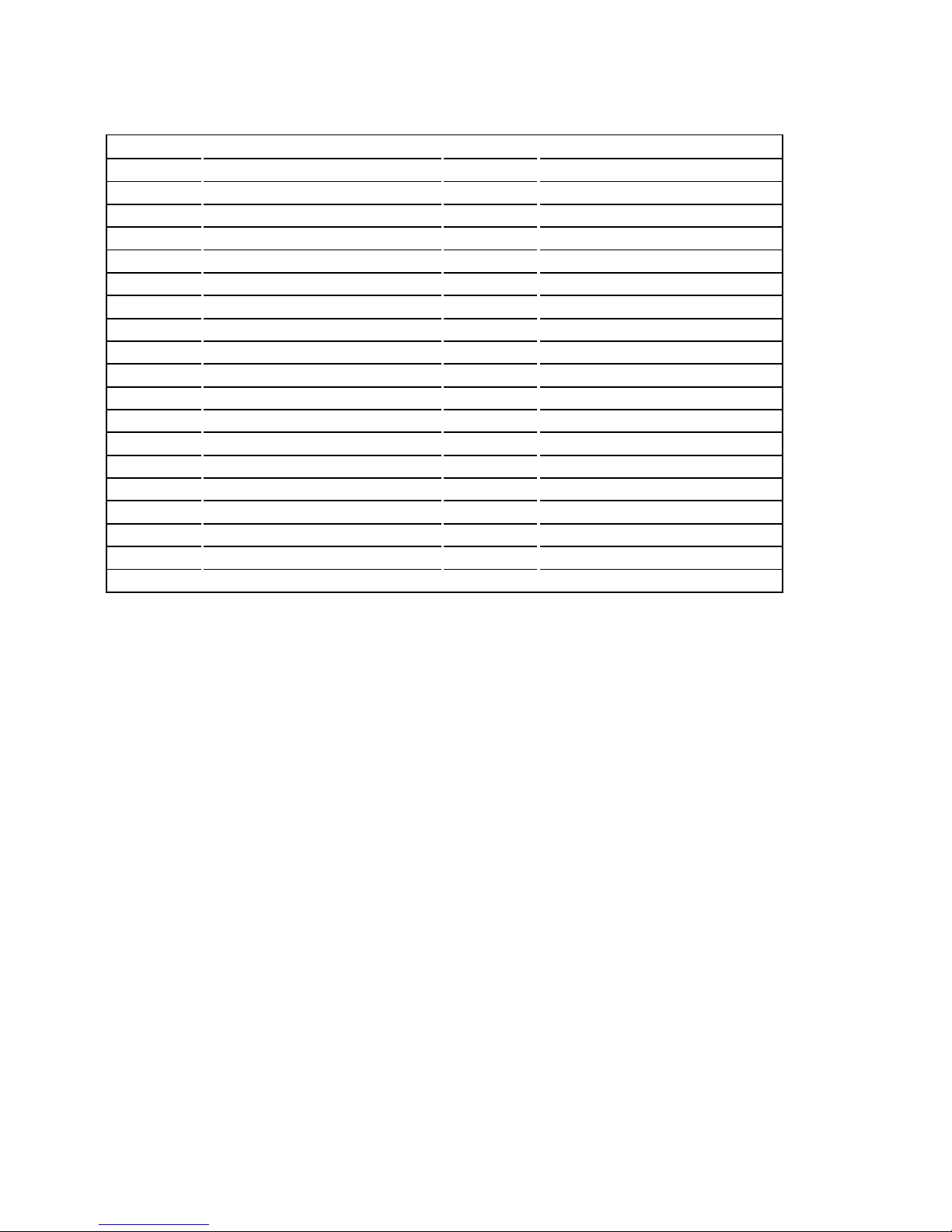
Connector Description Connector Description
CF1 CF card socket PCI PCI slot
DDR2 DDR II SO-DIMM socket CN1 IO Port
CN2 IO Port CN3 IO Port
CN9 Battery connector CN10 Panel InverterConnector
CN11 40pin IDE connector CN13 NVRAM 4MB Connector
CN15 FAN connector CN16 LVDS LOW ER DATA connector
CN17 FAN connector CN18 USB connector
CN19 LVDS UPPER DATA connector CN20 SATA connector
CN21 HDD POWER connector CN22 HDD POWER connector
CN23 SATA connector CN24 RESET connector
CN25 IR CN26 USB connector
CN27 LPT CN28 USB connector
CN29 CD IN connector CN30 FAN connector
CN31 PS2 KB/MS connector CN32 LAN+USB
CN33 LAN+USB CN34 AUDIO connector
CN35 COM1/2 connector CN36 COM3/4 connector
CN37 SYSTEM POWER CN38 IO POWER
CN39 RCA CN40 CRT+DVI
CN42 DOOR connector
10
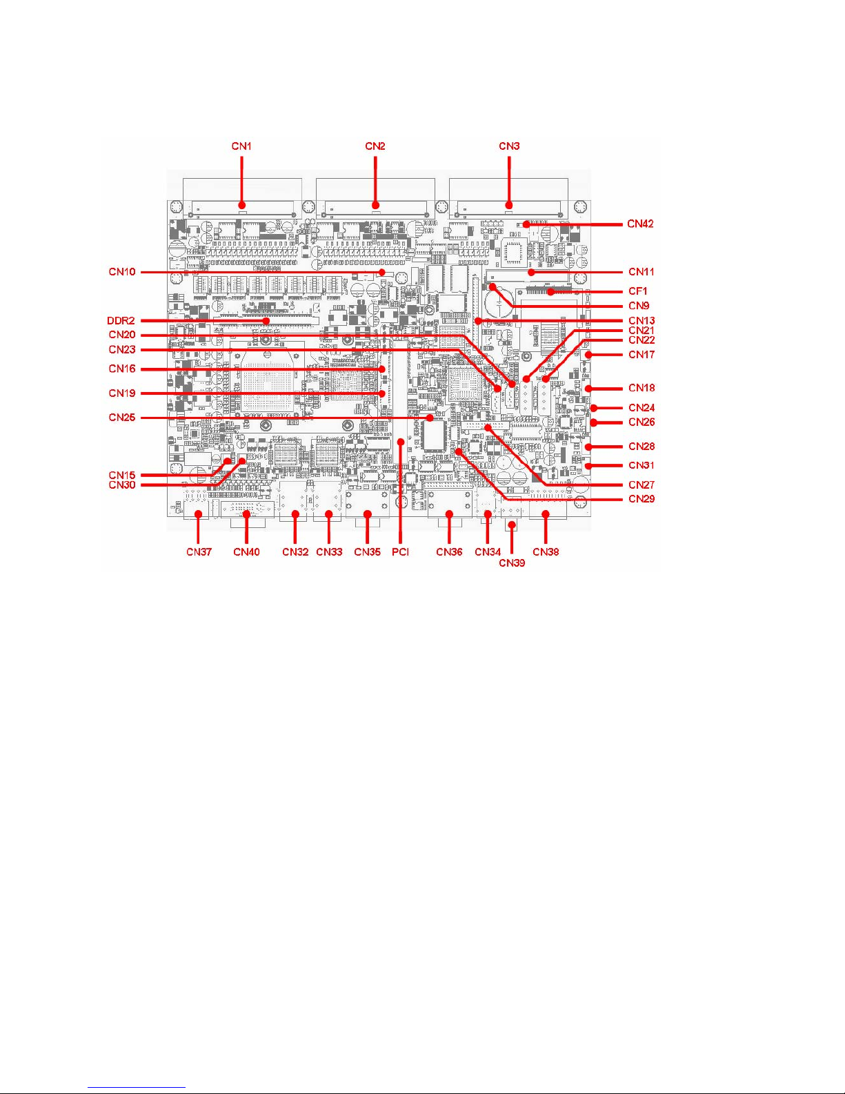
2-2 Location of Connectors
Location of Connectors on the Component Side

11
2-3 List of Jumpers
Connector Description Connector Description
JP3 NANDrive JP4 NANDrive WRITE PROTECT
JP5 PANEL VOLTAGE JP6 CF
JP7 CLEAR CMOS JP12 422RX_EN
JP13 422/485TX_EN JP14 232/422/485 SELECT
12
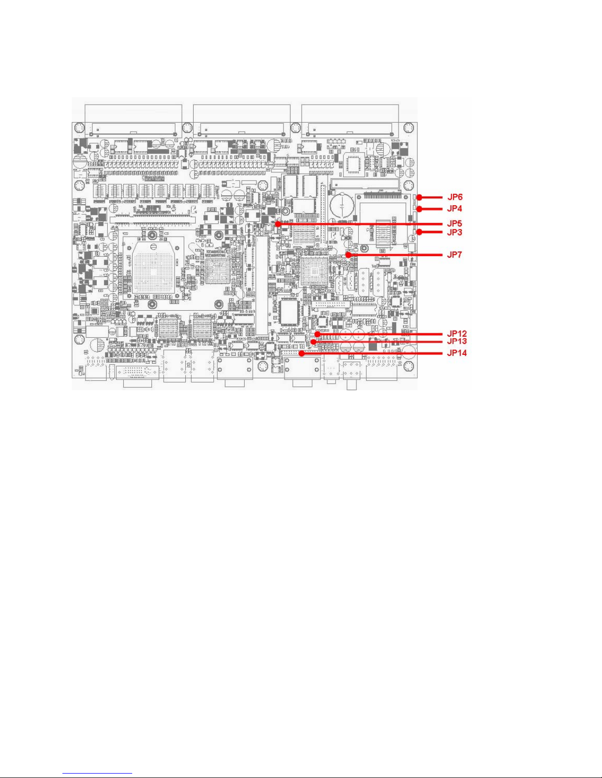
2-4 Location of Jumpers
Location of Jumpers on the Component Side
13
2-5 Connector Pin Assignment and Jumper Setting
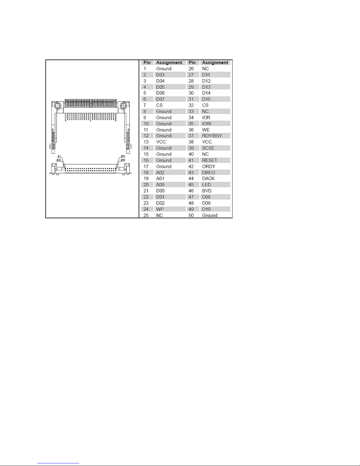
CF1: CompactFlash Card Socket
14
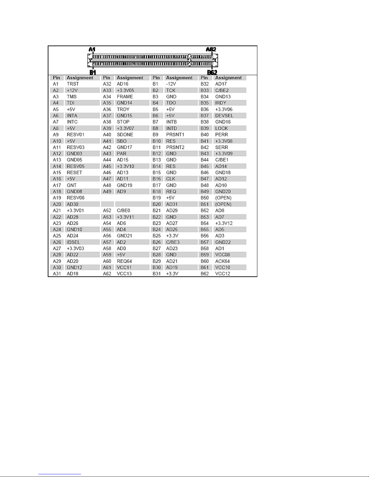
PCI: PCI Slot (PCI 2.2; 5V)
15
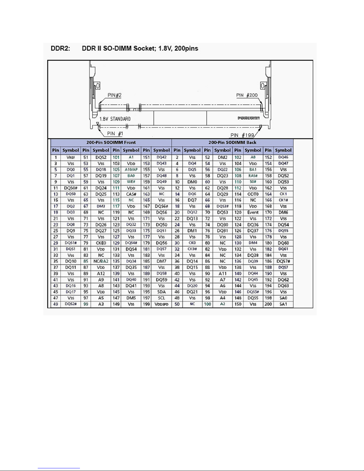
DDR2: DDR II SO-DIMM Socket; 1.8V, 200pins
 Loading...