

Page 1

®
TURRET REPLACEMENT KIT RP-RM46
INSTALLATION INSTRUCTIONS
for CRANK-UP SATELLITE ANTENNAS
(Except Combination Mounts - RM-4610, etc.)
Directions for Turret Replacement
1. Crank antenna to vertical position.
2. Remove crank assembly inside vehicle
using #2 Phillips screw driver.
3. Is there a nut in the center hole of the
directional handle? Remove this nut,
using a 9/16” socket wrench.
4. Remove directional handle by pulling
down. Depending on the original installation, it may be difficult to remove.
5. To remove backup assembly from
turret, remove the two (2) clamps and
four (4) screws. Use 5/16” socket, nut
driver or wrench. Do not pull on the
wires attached to mount.
6. Remove three (3) screws fastening
turret to mount. Use 5/16” socket, nut
driver or wrench.
7. Lift mount straight up until free of all
parts. If the worm shaft stays in the
turret, remove by pulling on aluminum
hex shaft (it should come out easily).
8. Remove and clean outer bearing. Use
damp cloth to remove grime, then
replace bearing.
9. Remove and clean gear and hub area.
Add a small amount of silicone grease
to area where gear and hub rub.
10. Replace new turret assembly on mount.
Rotate assembly until the three mounting holes line up. Carefully fasten with
three screws in the existing threads.
Be sure turret turns freely on mount. Be
sure the handle lock is in the rotate
position before checking turret
movement.
11. Rotate square shaft with shaft pin, until
pin faces up at approximately 45°.
12. Replace worm shaft into top of turret.
Be sure the spring and spacer are on
the shaft.
13. Line up hex shaft with hex hole in gear.
Slide into hole.
You may need to slightly turn the
square shaft to align teeth on worm
gear to teeth on worm shaft. The
square shaft will rotate as worm shaft is
slid down into place.
14. Make sure O-ring in on plastic plug.
Carefully screw plug into turret top. Do
not cross thread. Tighten snugly. Do not
overtighten — O-ring will squeeze out
from under nut.
15. Replace backup structure. Be sure to
route wires the same as they were
before disassembling backup structure.
16. Replace the interior parts that were
removed.
To replace the directional handle, refer
to instructions on page 4 for cutting
the length.
NOTE: For thick roofs, you may need a
longer threaded rod, part number 2162031.
Order from Winegard Customer Service at
1-800-288-8094.
Winegard Company • 3000 Kirkwood St. • Burlington, IA 52601-2000 • 319/754-0600 • Fax 319/754-0787 * www.winegard.com
Printed in U.S.A. © 2003 Winegard Company 2452032
1
Page 2
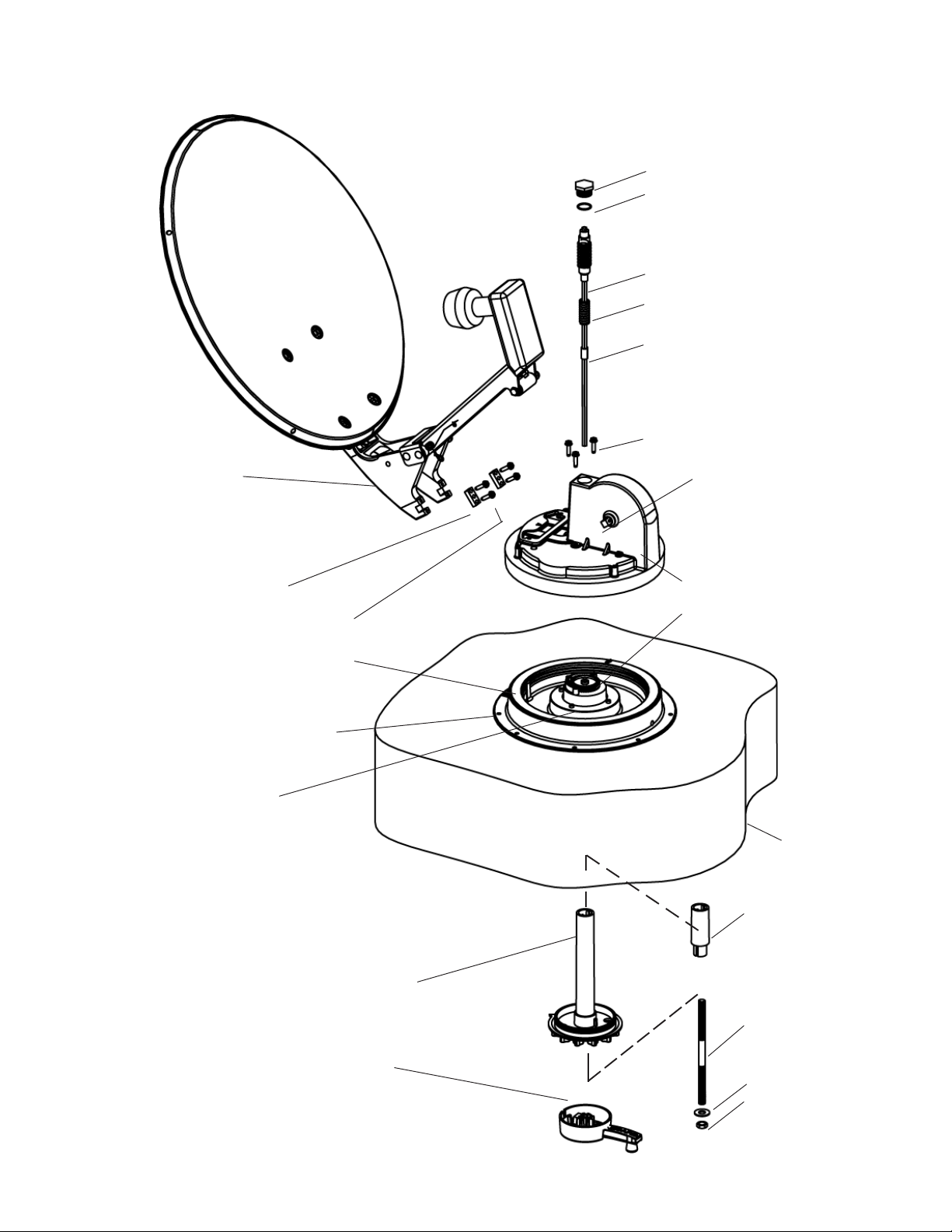
FIGURE 1
PLASTIC PLUG
O-RING
WORM SHAFT
SPRING
SPACER
SCREWS (TURRET)
BACKUP FRAME
ASSEMBLY
CLAMP
SCREWS (CLAMP)
OUTER BEARING
TURRET BASE
HUB
SHAFT PIN
(Referred to in #11.)
TURRET ASSEMBLY
ELEVATE SHAFT GEAR
ROOF
EXTENSION,
DIRECTIONAL
HANDLE
DIRECTIONAL HANDLE
CRANK ASSEMBLY
THREADED
ROD
FLAT WASHER
HEX NUT
2
Page 3

Instructions for Cutting Directional Handle Length
1. Place nut on threaded rod.
2. Measure and cut threaded rod with hack
saw. Use the chart, Figure 2, to determine the length.
3. Remove the nut over cut end of threaded
rod. This cleans the threads after cutting.
4. Thread cut end of rod into hub.
5. Install the ceiling plate. The rotate/lock
lever must point toward rear of vehicle.
Be sure rotate/lock lever is pointing toward
back of vehicle and hole in ceiling aligns
with hole in ceiling plate.
NOTE: Make sure large and small keyways
line up in the hub and directional handle!
6. Measure and cut the directional handle,
Figure 3 and chart, Figure 2. NOTE: A
tube cutter is recommended for cutting
the directional handle. This gives a
square cut; a hacksaw does not. If using
an extension, allow for extra thickness
(see #7).
Figure 4 shows what points to measure
between, with and without a roof wedge.
7. The directional handle
and threaded rod will fit
roofs up to 5-1/4” thick. If
you are using wedges to
compensate for roof/ceiling slope, be sure to
allow for this extra thick-
WITH ROOF WEDGE
ness. You may add an
extension to the
directional handle for
Measure from top of
ROOF WEDGE to ceiling.
thicker roofs. Each
extension will increase
the length of the directional handle by 2-1/4”.
FIGURE 2
Roof Directional Threaded Worm Gear
Thickness Handle Length Rod Length Shaft Length
(Figure 3) (Figure 4)
1-1/2” .......... 2-7/8”............ 2-3/4” ...........2-7/8”
1-3/4” .......... 3-1/4” ............ 3” .................3-1/8”
2” ................ 3-1/” .............. 3-1/4” ........... 3-1/2”
2-1/4” .......... 3-7/8” ............ 3-1/2” ........... 3-7/8”
2-1/2” .......... 4-1/8” ............ 3-3/4” ........... 4-1/8”
2-3/4” .......... 4-1/2” ............ 4” .................4-1/2”
3” ................ 4-3/44”.......... 4-1/4” ........... 4-3/4”
3-1/4” .......... 5” .................. 4-5/8” ...........4-7/8”
4” ................ 5-3/4”............ 5-1/2” ........... 5-3/4”
4-1/4” .......... 6-1/8” ............ 6” .................6-3/8”
4-3/4” .......... 6-5/8” ............ 6-1/8” ........... 6-3/8”
5” ................ 6-7/8”............ 6-3/8” ........... 6-5/8”
5-1/4” .......... 7-1/8” ............ 6-5/8” ........... 7”
5-1/2” .......... 7-3/8” ............ 6-7/8” ........... 7-1/4”
FIGURE 3
HANDLE
LENGTH
CEILING
PLATE
DIRECTIONAL
HANDLE
WITHOUT ROOF WEDGE
Measure from top of
ROOF to ceiling.
TOP OF ROOF
FIGURE 4
TOP OF ROOF WEDGE
CEILING
CEILING
3
Page 4

Refer to drawing to identify parts.
STEP 1. Release spring at base of feed arm.
(This allows you to remove elevating shaft and
spring without the dish popping up.) Next,
lower antenna to travel position.
STEP 2. Loosen set screw on elevating crank
handle. Remove crank, #1, directional handle,
#2 and extention, #3 (if used).
STEP 3. On roof of vehicle, unscrew plug, #4,
from top of gear housing. Use 1/4” hex head
nut driver and turn elevating shaft counterclockwise to remove. Carefully pull out
elevating shaft and spring assembly.
STEP 4. To replace elevating shaft, slide
spacer #5A, spring, #6, onto elevating shaft,
#5. Keep shaft in vertical position and slide
into gear housing. You must match the hex
shape of the elevating shaft with the hexshaped hole in the gear inside the gear
housing. Do not force. There will be some resistance as you slide the elevating shaft into
the housing. Carefully push in until the top of
the shaft is down in the top of the housing. Using 1” combination wrench, replace plug, #4,
into top of housing.
STEP 5. Raise dish and reattach spring at
base of feed arm.
STEP 6. If necessary, adjust elevating shaft
length before replacing directional handle, extensions (if used) and elevating crank handle.
See owner’s manual for instructions.
STEP 7. Replace directional handle, extensions (if used) and crank handle.
4
 Loading...