

Page 1
Stationary Electronics Replacement Kit
Model RP80RTS
For help, email help@winegard.com or call 1-800-788-4417.
For receivers and programming, call 1-866-609-9374.
For up-to-date information on receiver compatibility and
programming, visit www.winegard.com/receivers.
2452280
Page 2
Parts of the Antenna Installing the Replacement
Removing the Existing
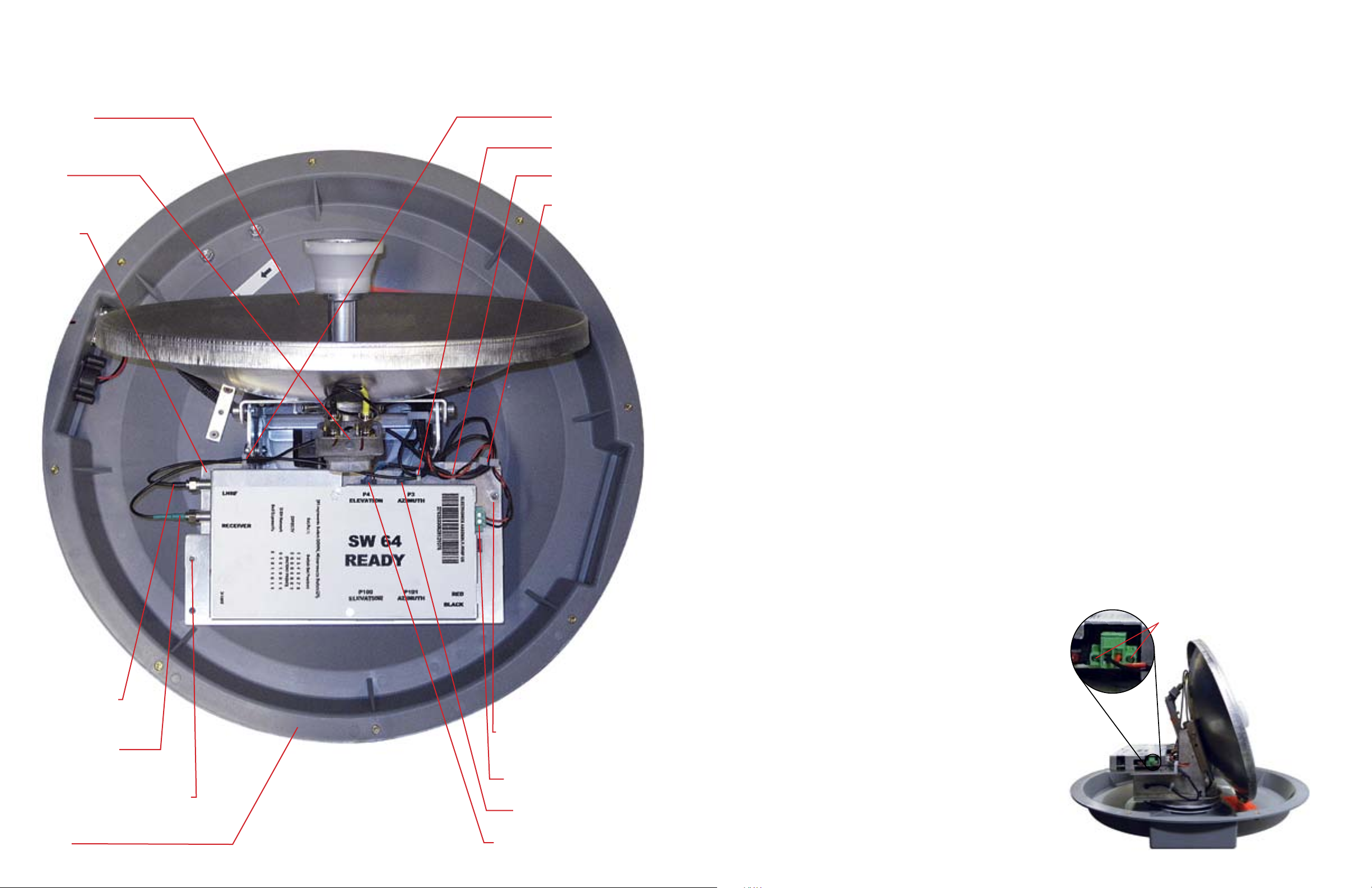
Overhead View (Dome Removed)
Reflector
LNB
Frame
Cable harness 1
Cable harness 2
Cable harness 3
Cable harness 4
Stationary Electronics Box
1.
Before starting, turn off the power to the unit,
and unplug the unit from the receiver.
Using a #2 Phillips screwdriver, remove the
2.
screws holding the dome to the base.
If applicable, remove the screws connecting
the handle to the unit, and remove the
handle. Set these screws aside; you will need
them later.
Remove the dome.
3.
4.
With both hands on either side of the
reflector, carefully tilt the reflector forward.
5.
With a small flat screwdriver, loosen the
two screws on the side of the power supply
connector, and remove the power supply.
Do not loosen the two screws on the top of
the power supply. Refer to the image on the
bottom of this page.
6.
Loosen and remove the two coaxial cables
underneath “LNBF” and “RECEIVER” with a
7
/16” wrench.
Remove all cables from the cable harnesses
7.
marked in the image to the left.
Remove the two screws holding the
8.
electronics box to the frame with a
wrench. Gently slide the electronics box
away from the frame.
1
/4” Allen
Stationary Electronics Box
1.
Insert the second (larger) motor connection
into the port underneath “P4 ELEVATION” on
the replacement stationary electronics box.
Insert the first (smaller) motor connection
2.
into the port underneath “P3 AZIMUTH” on
the replacement stationary electronics box.
Align the two holes in the electronics box
3.
and the frame. Insert a screw through each
hole, and tighten with a 1/4” Allen wrench.
4.
Connect the coaxial cable running from the
left side of the LNB to the port underneath
“LNBF.” Make sure the cable still runs behind
the LNB. Tighten until fingertight, and then
tighten a quarter turn with a 7/16” wrench. Do
not overtighten!
Connect the other coaxial cable to the
5.
port underneath “RECEIVER.” Tighten until
fingertight, and then tighten a quarter turn
with a 7/16” wrench. Do not overtighten!
6.
Plug in the power supply connector, and tighten
the two screws on the side of the connector
with a small flat screwdriver.
7.
See “Routing the Cables in Cable Harnesses”
on the next page to finish installing the
electronics box.
Coaxial cable
underneath “LNBF”
Coaxial cable
underneath “RECEIVER”
Screw holding electronics
box to the frame
Base
Screw holding electronics
box to the frame
Power supply connector
First motor connection
Second motor connection
The electronics box is still
WARNING
pull on the electronics box.
9.
Push down the lock on the first motor
connection. Remove the first motor connection
from the port below “P3 AZIMUTH.”
10.
Push down the lock on the second motor
connection. Remove the second motor
connection from the port below “P4 ELEVATION.”
Remove the electronics box.
11.
12.
Continue with “Installing the Replacement
Stationary Electronics Box” on this page.
tethered to the unit. Do not
Two screws to remove from power supply
Page 3

Routing Cables through
Re-Installing the Dome
the Four Cable Harnesses
1.
Route the two coaxial cables underneath
“LNBF” and “RECEIVER” through cable
harness 1.
Route the cable running from “RECEIVER”
2.
and the cable running from the right side of
the LNB through cable harness 2.
3.
Route the first and second motor connection
cables through cable harness 3. Also, route
the power cable through this cable harness.
Route the first and second motor connection
4.
cables and the power cable through cable
harness 4.
Changing Switch Settings
1.
Replace the dome.
Align the holes in the base with the holes in
2.
the dome. If installing a handle, align the holes
in the handle with the holes in the base. To
protect the cable connections from accidental
damage, install the handle using the two holes
closest to the cable connections.
If replacing the dome on a roof-mounted
3.
unit, make sure that the decals on the
dome face perpendicular to the main and
secondary ports. If replacing the dome on a
portable unit, make sure that the decal faces
opposite the main and secondary ports.
Thread a screw through each hole, and
4.
tighten with a #2 Phillips screwdriver.
Do not overtighten!
You must change the numbered switches found
on the electronics box under the dome before
replacing the dome.
Change the switch settings to the settings for
your programming provider. Hybrid mode is
for use in areas where the 129° satellite is not
available and standard DISH® settings fail to
provide HD programming.
Once the switch settings are
appropriately set for your
programming provider, the
dome can be replaced.
DIRECTV
1 2 3 4 5 6 7 8
®
1 2 3 4 5 6 7 8
Key
0 = Up
1 = Down
DISH
Winegard Company • 3000 Kirkwood Street • Burlington, IA
52601 1-800-288-8094 • Fax 319-754-0787 • www.winegard.com
Printed in U.S.A. ©2012 Winegard Company 7/12 2452280
Bell TV™
1 2 3 4 5 6 7 8
DISH Hybrid
1 2 3 4 5 6 7 8
Winegard is a registered trademark of Winegard Company.
DISH is a registered trademark of DISH Network L.L.C.
DIRECTV is a registered trademark of DIRECTV, Inc., a unit of Hughes Electronics Corp.
Bell TV is a registered trademark of Bell Canada, Inc.
Disclaimer: Although every effort has been made to ensure that the information
in this manual is correct and complete, no company shall be held liable for any
errors or omissions in this document. Information provided in this document was
accurate at time of printing.
 Loading...