

Page 1
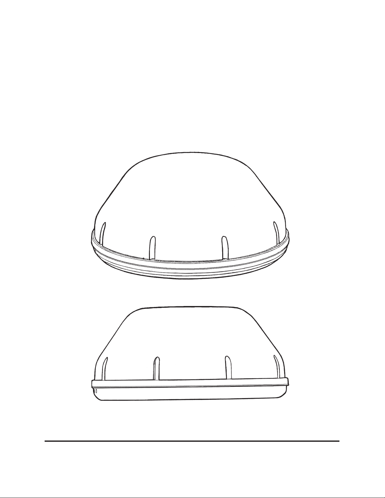
®
WINEGARD
TM
Movin’ View
Digital Satellite Mobile Antenna for Two Receivers
for Use While Stationary or In-Motion
Model MV-4002
Made in the U.S.A. U.S. Patent Nos. 6,023,247; 6,188,300
Winegard Company • 3000 Kirkwood St. • Burlington, IA 52601-2000
319/754-0600 • FAX 319/754-0787 • www.winegard.com
Printed in U.S.A. © Winegard Company 2005 2452062 Rev. 5/05
1
Page 2
Introduction/How Does Digital Satellite TV Work?
About this manual —We hope this manual will provide clear instructions to install and
operate MV-4002. Two symbols have been used —
Indicates caution should be taken!
!
Introduction
Congratulations! You have purchased one of
Winegard’s latest developments in the mobile satellite
reception product line —the Movin’ ViewTM. This system, used with your digital satellite receiver, will
deliver the best reception possible using GPS (Global
Positioning System) and precision gyroscopes.
How Does Digital Satellite
TV Work?
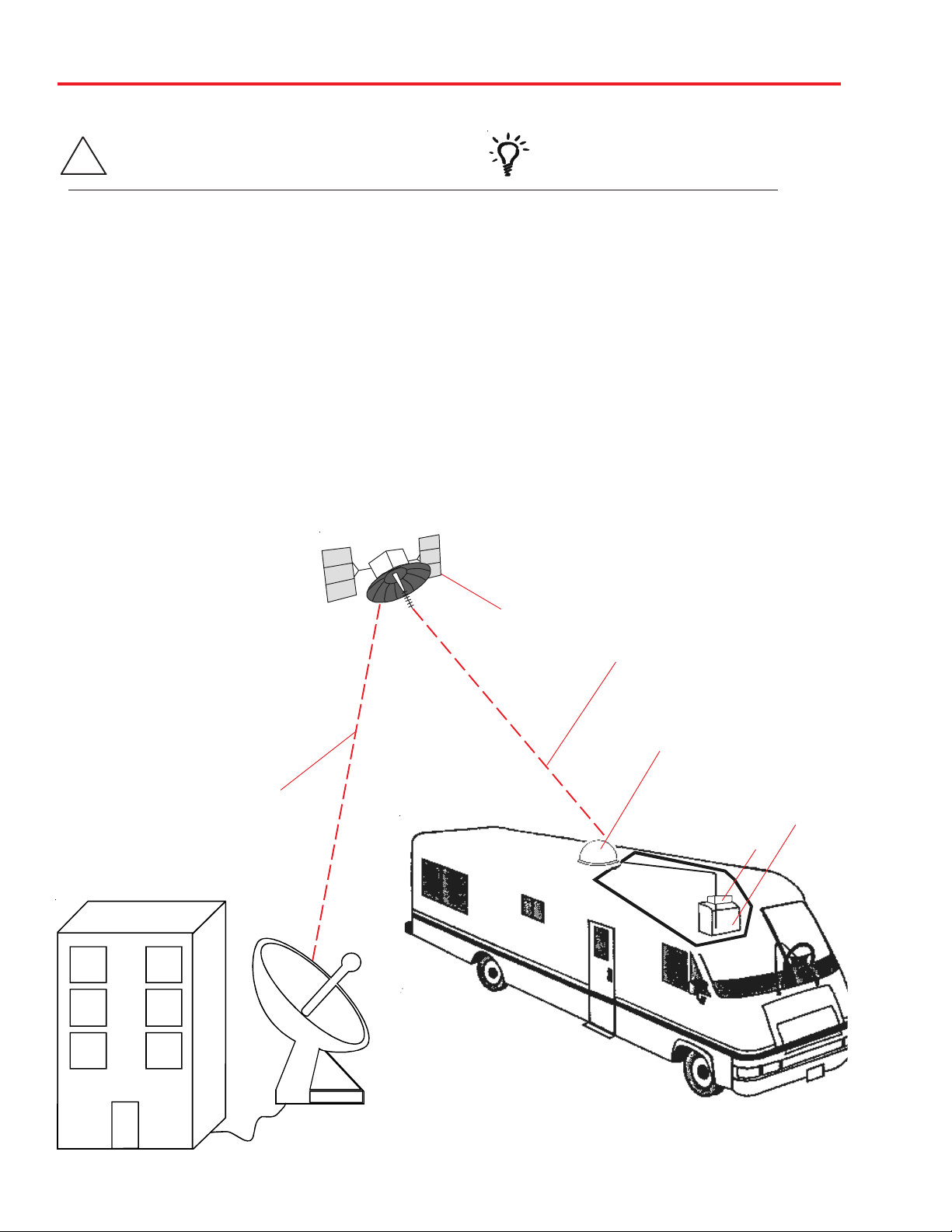
Satellite programming originates from an “uplink” facility on Earth — the facility receives many signals from
different sources, combines the signals digitally and
transmits to the satellites. The satellites (22,300
miles above Earth) receive the uplink signal, amplify it
and then transmit it back to earth in
the Ku frequency band. This signal
is concentrated and reflected to the
LNBF* located at the “focal point” of
the dish. The LNBF amplifies and
converts the signal to the 950 to 1450
MHz range. The signal is then passed
through a coaxial cable to the receiver
where individual channel selection and processing take place.
For Programming information call:
DISH NETWORK® - 1-800-333-DISH (1-800-333-3474)
DIRECTV® - 1-800-DIRECTV (1-800-347-3288)
EXPRESSVU® - 1-888-SKYDISH (1-888-759-3474)
Your new Winegard RV Digital Satellite System is an
easy-to-use satellite TV reception system. Because it
mounts on the top of your recreational vehicle, it goes
where you go and provides quality reception of digital satellite signals. Check with your program provider for exact
coverage area.
MV-4002 features:
Indicates suggestions to make
processes easier for you.
• GPS technology
• Easy “one-button” operation
• Compatible with most digital satellite receivers
• Ability to toggle between satellites using remote
control, if subscribing to multisatellite programming
• Winegard warranty
DIGITAL BROADCAST SYSTEM
SATELLITE(S)
HIGH POWER KU-BAND
DOWNLINK SIGNAL
* Low Noise Block Converter Feed
UPLINK SIGNAL
PROGRAMMING UPLINK
CONTROL CENTERS
DIRECTV® is an official trademark of DIRECTV, a unit of GM Hughes Electronics Corporation.
DISH NetworkTM is an official trademark of EchoStar Communications Corporaton.
WINEGARD DIGITAL SATELLITE
SYSTEM ANTENNA
TELEVISION
SET
RECEIVER
2
Page 3
Quick Reference Guide
NOTICE!
This model is PRESET for DIRECTV® receivers.
If you have a DISH Network
®
or ExpressVu
®
(Canada) receiver,
you must change the numbered switches inside the dome.
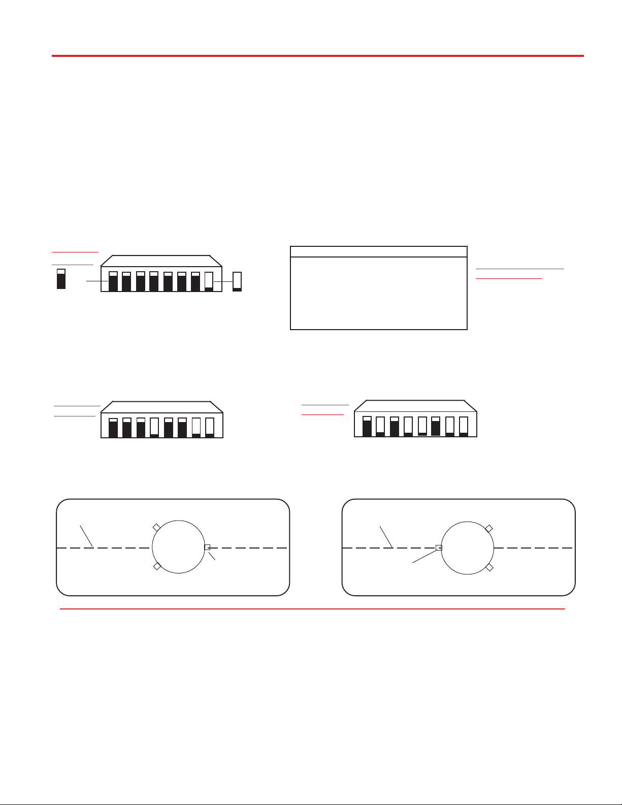
TO CHANGE SWITCHES INSIDE DOME —
1. Remove screws holding dome to base and remove dome. Place dome in safe spot to avoid damage.
Switches will be set at 101° for DIRECTV®. You will be changing these switches.
MOUNTING
OPTION A
0 = UP
1 2 3 4 5 6 7 8
0 0 0 0 0 0 0 1
1 = DOWN
(#1 represents Switch DOWN; #0 represents Switch up)
Sat. Rcvr. Mt. Option Switch Set Position
...................................
DIRECTV A 0 0 0 0 0 0 0 1
(FACTORY PRESET)
DIRECTV B 1 0 0 0 0 0 0 1
DISH NETWORK A 0 0 0 1 0 0 1 1
DISH NETWORK B 1 0 0 1 0 0 1 1
ExpressVu A 0 1 0 1 1 0 1 1
ExpressVu B 1 1 0 1 1 0 1 1
2. Determine which programming you will be using. This will determine how you set your switches.
For DISH Network set switches to 119°. For ExpressVu®, set switches to 091°.
MOUNTING
OPTION A
0= UP 1= DOWN
1 2 3 4 5 6 7 8
0 0 0 1 0 0 1 1
Models MV-4002, MV-4000, MV-4005
1 2 3 4 5 6 7 8
MOUNTING
OPTION A
0= UP
1 2 3 4 5 6 7 8
0 1 0 1 1 0 1 1
MOUNTING OPTIONS
SHOWN BELOW
1= DOWN
FIGURE 1A, OPTION A
FRONT OF VEHICLE
CENTER LINE OF VEHICLE
DIRECTV® receivers must be set to the two satellite, oval dish setting. Refer to your receiver manual.
DISH Network receivers must either have the check switch set for SW42 or unknown, no satellite found. See
page 5.
The satellite system has two modes of operation; Tracking Mode and Sleep Mode. When you first turn the
unit on it enters Tracking Mode. In this mode the unit will search and actively follow the satellite as the vehicle
travels. Tracking Mode ends when the unit has successfully finished its search and the vehicle has not moved
for six minutes.
Sleep Mode, this is the unit at rest mode. During Sleep mode the dish will toggle between primary and secondary satellites as you change channels with the remote. The unit enters Sleep mode about six minutes after
a successful search if stationary, or six minutes after the vehicle stops moving.
MV-3500
MV-4002
BASE FOOT
(MUST BE PARALLEL
TO CENTER LINE)
MOUNT OPTIONS A AND B
FIGURE 1B, OPTION B
FRONT OF VEHICLE
CENTER LINE OF VEHICLE
BASE FOOT
BACK OF VEHICLE
(MUST BE PARALLEL
TO CENTER LINE)
MV-4002
BACK OF VEHICLE
3
Page 4

Operation
1. Turn on receiver and television set. The MV-4002
must be connected to a receiver that is plugged
into 120 VAC.
2. Verify that you are getting the receiver’s menu
screens on the television. These screens are available with or without the dish finding the signal.
3. Turn the power switch on for the MV-4002.
The dish should start moving, making one or two
revolutions before it stops to acquire GPS. This can
take a few moments or up to 10 minutes. Normal
operation will be less than a minute.
4. Once the unit has acquired GPS, the dish will
begin its search.
a. The dish will pause on the signal long enough to
determine which satellite it has found.
b. If it moves off the signal , it is in an effort to verify
the signal and it should return to the signal shortly.
5. After the unit has verified that it has the correct
satellite, it will continue to fine tune for about 6 minutes (unless the vehicle is in-motion, see 7 below).
6. At the end of 6 minutes the unit will move to check
it’s alternate satellite then move back to the primary
and go to sleep. See page 3 for a description of
Sleep Mode.
7. While the vehicle is in motion, the unit will not enter sleep mode after a successful search. Instead it
will wait until the unit has stopped moving for 6 minutes before entering sleep mode.
8. If you do not have signal, see Troubleshooting,
p. 11.
Recovery from Signal Interruption—
While traveling, the signal will be interrupted
when the line of sight to the satellite is blocked.
Signal is acquired again after line of sight is restored.
If signal is interrupted for more than 15 seconds, the
system automatically enters the search routine. The
length of time for the TV picture to recover depends on the receiver model you are using.
The unit must travel in straight
line for 10 seconds when starting
to operate in motion.
4
Page 5
To toggle between satellites when subscribing to multi-satellite programming—
While in Sleep Mode, the MV-4002 will toggle between the primary and seconday satellites for either
DISH Network or DIRECTV. Both have programming on more than one satelite.When a channel is
selected on the remote control and is not on the
satellite currently selected, the unit will automatically move to the correct satellite.
DIRECTV programming
1. DIRECTV receivers must be set for oval dish 2
sat selection to enable toggling between primary
101°W satellite and alternate 119°W satellite only.
(Consult receiver manual for procedure.) After
receiver is set for the correct dish selection, when
you request a channel located on a different satellite, the unit will automatically move to that
satellite.
DISH Network programming (DISH 500)
DISH Network receivers must have the “SW42”
switch installed in order to toggle between the primary 119 satellite and the alternate 110 satellite.
(Consult your receiver manual for the procedure to
reach the “check switch” menu.)
If a switch other than SW42 appears, or you
have an X in one of the boxes below the satellites, repeat Check Switch Steps.
5. Your system is now set up to toggle between satellites. It will automatically move to the correct
satellite when a channel is selected with your remote
control.
NOTE: Once these steps are completed, you
won’t have to perform this test again, unless
Check Switch was performed on another satellite dish, such as a home dish.
Toggle: Your Winegard Automatic
!
satellite dish will move from the
primary to the alternate satellite in
order to receive multi-satellite
programming.
To install the “SW42” switch:
1. Before turning on your MV-4002 system, make
sure that your satellite receiver and television are
turned on and your receiver is on the “point dish”
menu. (Consult your owner’s manual to reach this
menu.)
2. While the vehicle is stationary, turn on the MV4002 system and wait for signal acquisition on
satellite 119.
3. After signal is acquired, the system will continuously track the signal for approximately 6 minutes.
At the end of 6 minutes, the unit will enter sleep
mode. You now have 6 minutes to complete
Check Switch test. Consult your receiver manual
for instructions on running this test. Be sure that
Superdish and Alternate are unchecked if applicable.
Onscreen options may vary by receiver.
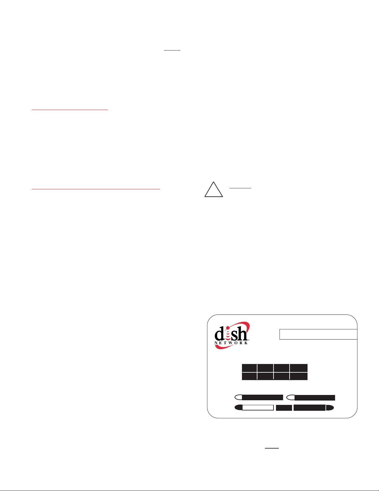
4. During the Check Switch Test, the receiver will
begin checking the switch by toggling between
satellites. When this is completed, SW42 will appear on the screen. It will be at the top of the
screen, satellite designations will be below, showing odd and even transponders. See illustration.
Install Summary
SW42
Input: 1 1 1 1
Satellite: 119 119 110 110
Polarity: Odd Even Odd Even
Status: Satellite reception verified
Superdish Alternate
Cancel Test Help
Check Switch screen display
NOTE: Be sure the “Superdish” and “Alternate” boxes ARE NOT checked.
5
Page 6
Parts Included • Tools Needed • How to Unpack
PARTS INCLUDED:
1 Radome
1 Power switch
1 Wall plate (white)
1 Surface mount box
1 Cable entry plate
TOOLS NEEDED FOR UNPACKING & INSTALLATION:
1 large yellow spade connector
2 small red spade connectors
All required screws and washers
1 base with electronics, dish, single LNBF
30’ power cable and 30’ coaxial cable
Level
Drill w/3/4” bit
1-1/4” hole saw (if mounting switch in wall)
3/8” Box/Open end wrench for dome screws
7/16” Open end wrench
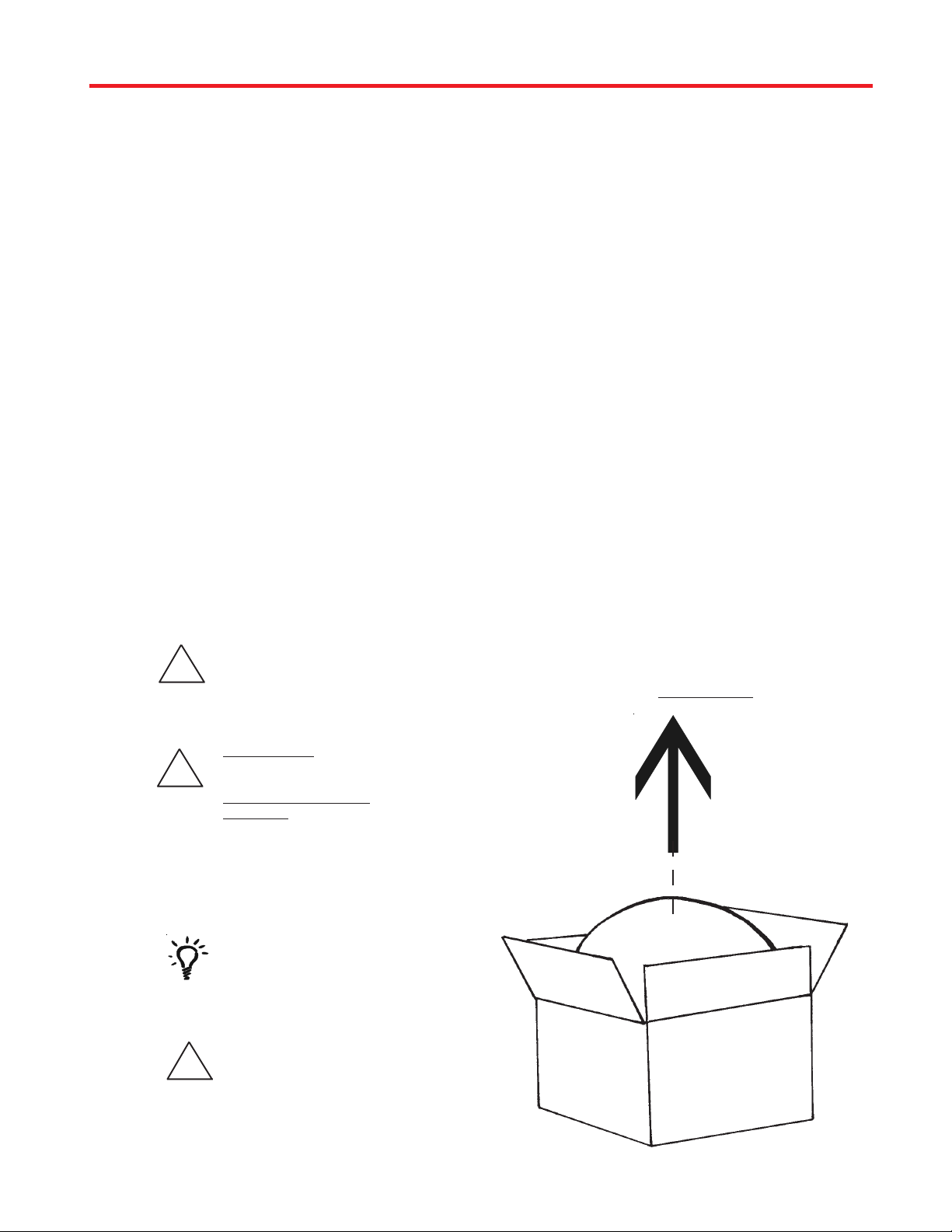
UNPACKING THE UNIT
1. Open box and remove packing material.
If using knife to open
!
!
carton, BE CAREFUL.
Do not cut the dome on
the unit.
BE CAREFUL when
removing unit. Dome is
attached to base by
ONLY THREE PEICES
OF TAPE!
Phillips screw driver #2
Sealant (consult RV manufacturer for proper type
for your roof material)
LIFT UNIT STRAIGHT UP
OUT OF CARTON!
2. Lift unit out of box vertically. Do not turn box and
“roll” out, or turn upside down to remove.
USE 2 PEOPLE
when removing the unit
from the carton.
Do not paint dome!
!
Painting dome will cause
signal degradation.
6
Page 7
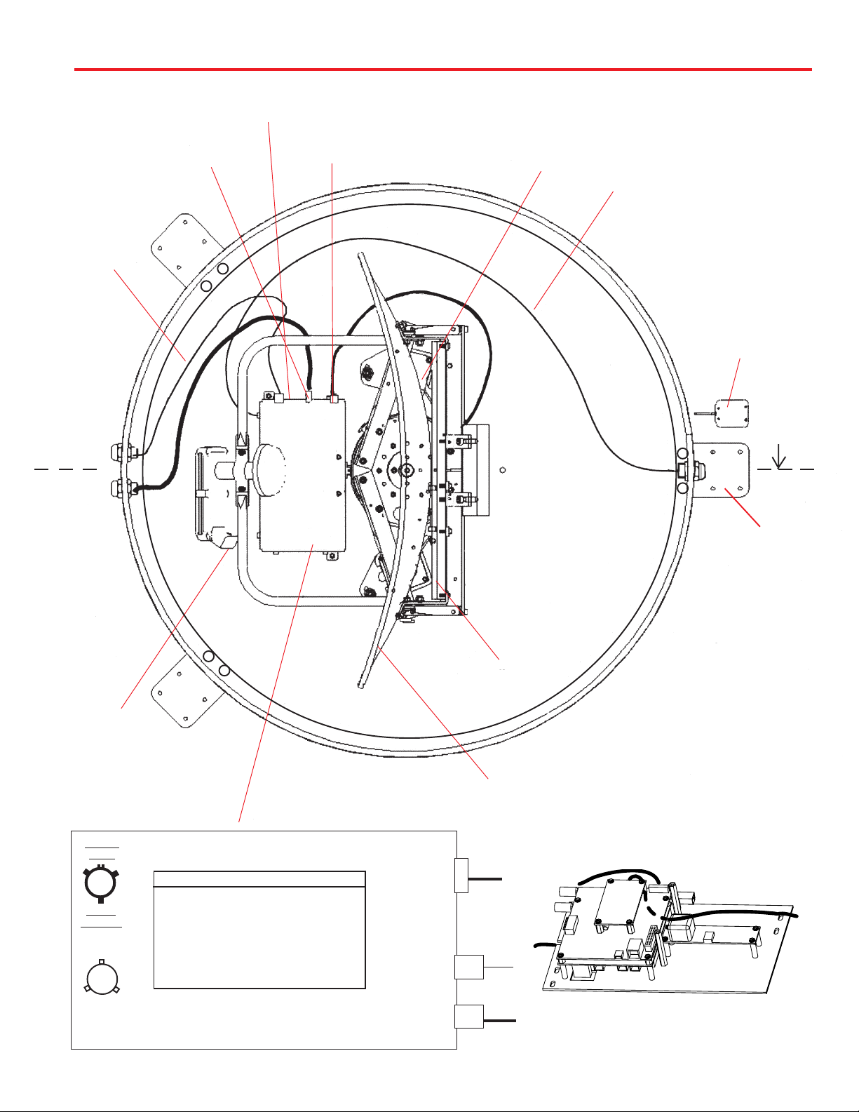
Base Diagram
FIGURE 2
+12VDC
POWER CABLE
SWITCH LOCATION
(SIDE OF BOX, SEE PAGE 3)
COAX CABLE AT
CONTROL BOX
CONTROL
BOX TO LNBF
CONTROL
BOX
(DETAIL
BELOW)
EL MOTOR
AZ MOTOR
GPS ANTENNA
CABLE
GPS
ANTENNA
CENTER
LINE OF THE
VEHICLE
FOOT
MUST BE
PARALLEL
TO THE
CENTER LINE
OF THE
VEHICLE
LNBF
VOLTAGE
CONTROL BOX DETAIL
Vehicle
Front
A
Mount
Option A
Vehicle
Front
B
Mount
Option B
(#1 represents Switch DOWN; #0 represents Switch up)
Sat. Rcvr. Mt. Option Switch Set Position
........................... 1 2 3 4 5 6 7 8
DIRECTV ...................... A ....... 0 .. 0 .. 0 .. 0 . 0 .. 0 .. 0 .. 1
(FACTORY PRESET)
DIRECTV ..................... B ....... 1 .. 0 .. 0 .. 0 . 0 .. 0 .. 0 .. 1
DISH NETWORK ................. A ....... 0 .. 0 .. 0 .. 1 . 0 .. 0 .. 1 .. 1
DISH NETWORK ................. B ......... 1 .. 0 .. 0 .. 1 . 0 .. 0 .. 1 .. 1
ExpressVu ................... A ....... 0 .. 1 .. 0 .. 1 . 1 .. 0 .. 1 .. 1
ExpressVu ................... B ....... 1 .. 1 .. 0 .. 1 . 1 .. 0 .. 1 .. 1
ELEVATIONP3AZIMUTH
P4
REFLECTOR
ELECTRONICS INTERIOR VIEW
RECEIVER
LNBF
7
Page 8
Installing unit on roof of vehicle —
Install in DRY conditions only!
IMPORTANT! Do not install this system
in the rain, or under any wet conditions. Mois-
ture may affect electronics and void your
warranty!
!
Installation
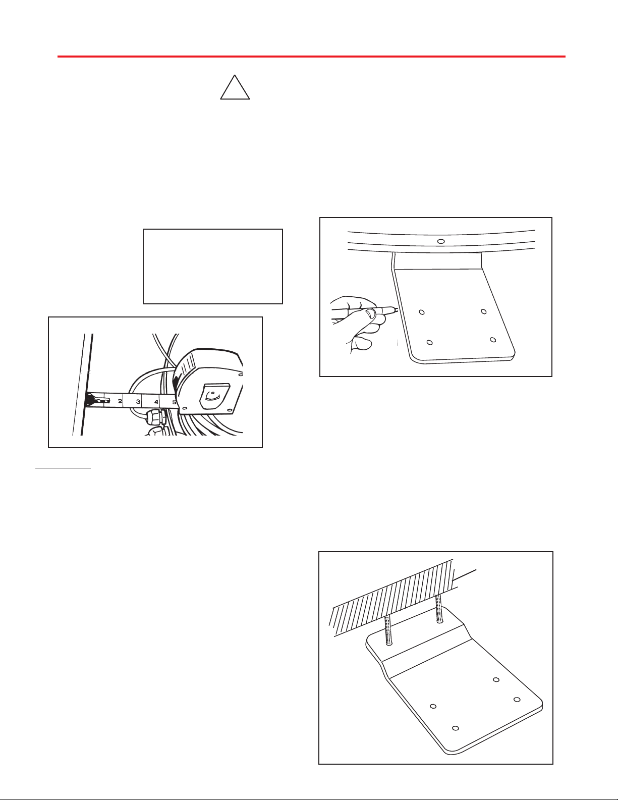
6. Place the unit on the roof in its permanent location and mark around the base bracket, Figure 4.
(Make sure the rear adjustable base foot is par-
allel with the center line of the vehicle. Refer
to page 3, Figure 1A ).
1. For best performance and to reduce signal acquisition time, park vehicle on a level surface; level
the RV.
2. Select a level spot on your roof for installation.
Using the chart,
determine the
minimum distances
to other equipment.
FIGURE 3
OBSTRUCTION
Obstruction Ht. Unit Clearance
8” .......................................... 4”
10” ................................... 11.5”
12” ...................................... 19”
15” ...................................... 32”
UNIT BASE
WARNING: Level the base front to back and
side to side. If base is not level the MV-4002 may
require more time to locate the correct satellite
or may not locate the correct satellite.
• Be sure no roof-mounted equipment is
blocking the satellite “line of sight”, Fig. 3
• You will need to decide where the wires will enter
the vehicle. A coax and a power wire (minimum 16
gauge) will need to be run into the vehicle.
WARNING: Many +12VDC sources can cause the unit
to fail. Select a filtered source, preferably a dedicated line to the battery.
7. Clean roof area where the base feet will be attached to the roof. Do not erase your marks!
FIGURE 4
8. Put approved sealant in the areas marked
for the base feet. Place base feet on top of the
sealant and screw down with the (4) #10
screws (provided) for each foot.
9. After all base feet are secured to roof, put
sealant around edge of feet and over screws.
Replace base on screws and reinstall nut.
FIGURE 5
BASE EXTERIOR
3. Remove dome. Place dome in safe spot to avoid
damage. Place base on vehicle roof in the location
selected.
4. Attach each mounting foot to base by securing
with two 7/16” nylocks. See page 7 for foot locations.
5. After selecting location for unit (see number 2),
put the unit on the centerline of the vehicle.
REAR MOUNTING FOOT MUST BE PARALLEL
WITH THE CENTER LINE OF VEHICLE. See pg. 7.
8
Page 9
Installation
GPS installation —
10. The GPS antenna is pre-wired and has a 1 meter
cable running through one of the connectors.
Determine location for GPS antenna. It is recommended you place the GPS antenna 3 feet from dome.
The recommended location for the GPS antenna is
based on having a level location and a clear view of the
sky for the best satellite signal acquisition. Do not secure GPS antenna to roof at this time.
IMPORTANT! The GPS must be located minimum of 3
feet away from obstructions on roof of vehicle. Antenna
must have a clear view of the sky for proper operation.
Cable entry installation —
1. Decide the best location for the cables to enter the
vehicle, and the location of the switch and receiver
(see “Installing the switch and receiver”on page 10). Drill
a 1/2” hole in the roof, push wires inside. Make proper
connections.
You must have filtered +12 VDC power source.
2. Place cable-entry plate over hole and cables. Screw
in place. Seal plate and screw holes with approved sealant (not included).
3. Depending on the length of the cable on the roof, you
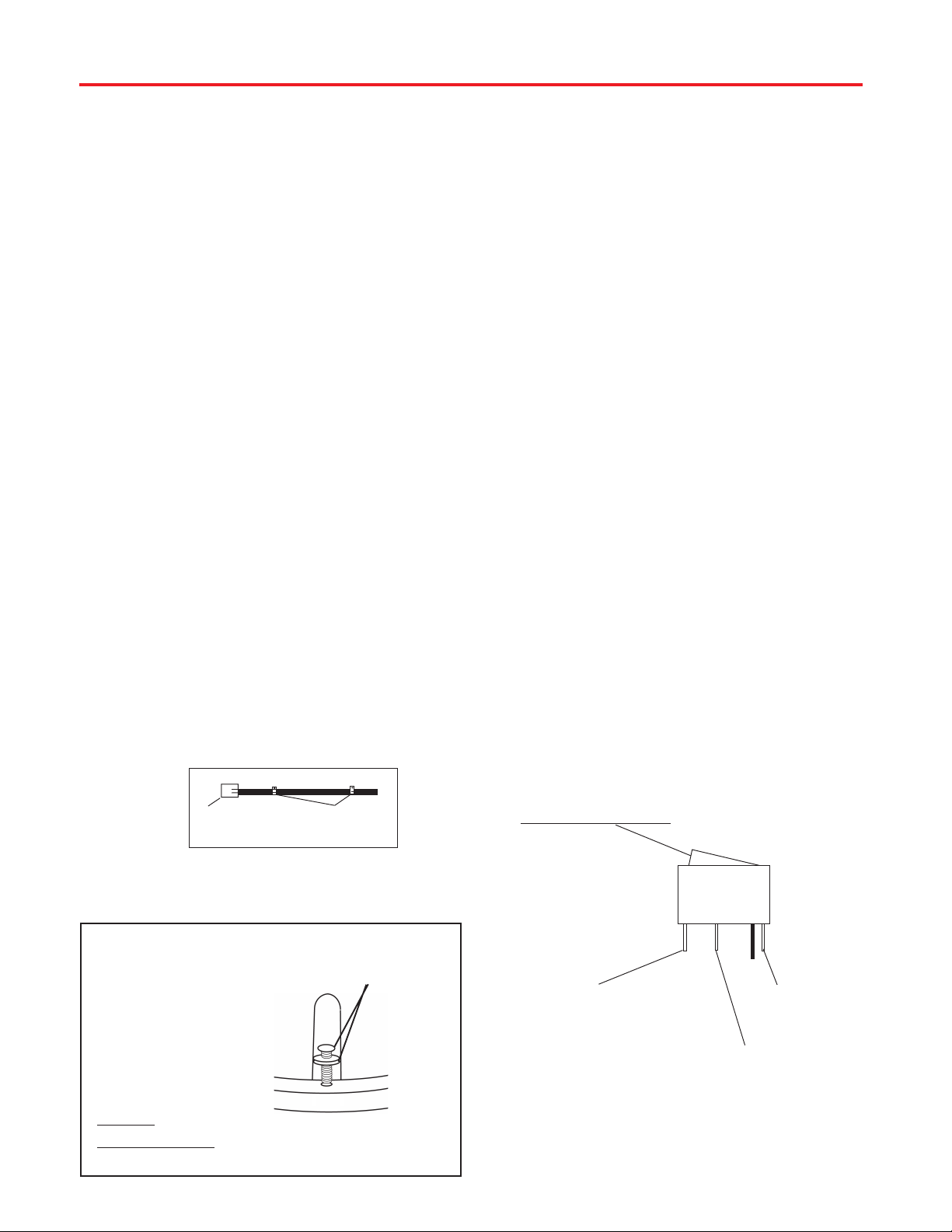
may need to use cable clamps or wire ties (not provided) between the unit and your cable-entry plate.
Clamping the cable every 12”-16” should eliminate any
unnecessary cable movement, Figure 6.
INSTALLING THE POWER SWITCH
1. Choose a location to install the MV-4002 power
ON/OFF switch. Remember when selecting a location
that you will need to run the +12VDC power cable from
the MV-4002 to the switch. Be sure the switch is in
the OFF position before continuing. See Figure 9
page 10.
Wall or panel mount: Drill 1-1/4” hole, pull wires
through wall or panel.
Surface mount: Determine location and direction of
box. Mount box and feed wire into one of the box open
ings. Select plate cover (brown or white provided) and
snap the rocker switch into the switch plate. Be sure
switch is off!
2. Connect the ground wire from the vehicle and the
BLACK ground wire from the MV-4002 together,
using large yellow spade connector.
3. Connect the YELLOW spade connector to
the silver spade on the switch.
4. Connect the RED wire from the MV unit to the
small RED spade connector.
5. Connect small RED spade connector to center
spade on switch.
6. Connect the +12 V power wire from the vehicle to
a small RED spade connector.
7. Connect small RED spade connect to isolated
spade on switch.
INSTALLING THE POWER SWITCH DIAGRAM
CABLE-
FIGURE 4
ENTRY
INSTALLING THE DOME
Insert screw in holes on dome
rim. Be sure bolt is vertical;
not tilted to side. Tighten to
20 in-lb., or approximately
until washer is visible
around screw head.
CAUTION:
DO NOT
OVERTIGHTEN!!
CABLE
CLAMPS
QUADREX
SCREW WITH
RUBBER
WASHER
(USE #2
PHILLIPS)
FIGURE 5
ON/OFF ROCKER SWITCH
WITH LIGHT
(Shown in OFF position.)
STEPS 2 & 3
TWO GROUND WIRES
1 FROM VEHICLE
1 BLACK WIRE FROM
SATELLITE DISH
STEPS 4 & 5
RED POWER
WIRE FROM
DISH
STEPS 6 &7
+12 V FROM VEHICLE
Terminals on switch have to be bent to fit in surface
mount box.
9
Page 10
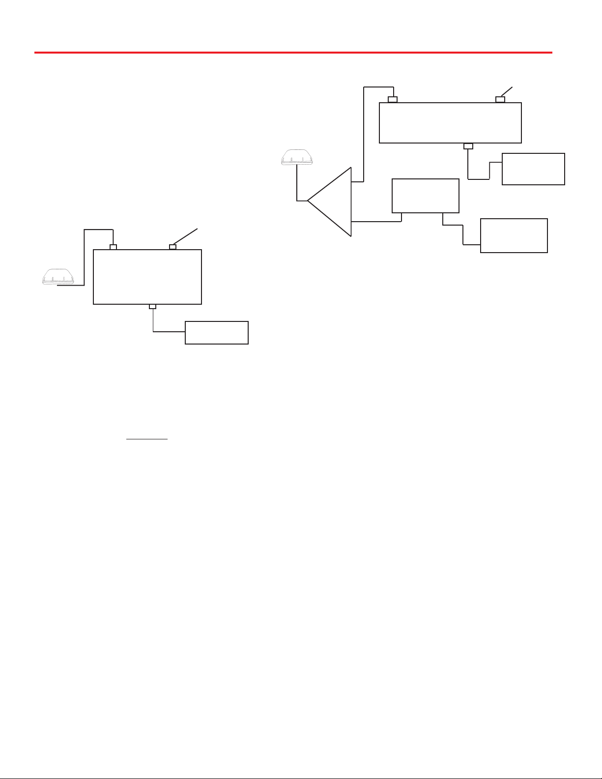
Connecting the receiver —
MV-4002 Tracking System
Connecting one receiver
1. Mount the DC Passive D575p demultiplexer in the
same cabinet as your receiver.
2. Connect the coax cable from the roof to the “input” on
the DC Passive D575p demultiplexer. Connect a coax
cable from the “sat receiver” on the DC Passive
demultiplexer. Connect other end of this cable to “satellite in” on receiver.
WIRING ONE RECEIVER
NOT USED
INPUT
D575p
DEMULTIPLEXER
DC PASSIVE
SAT RECEIVER
SATELLITE IN
Connecting two receivers—
Connecting first receiver:
1. Inside the vehicle, connect the coax cable from the
roof to the “IN” input on the splitter (SP-2052). Connect
a coax cable from one of the “OUT” ports or jack on the
splitter (SP-2052). Connect other end of this cable to
the “input” on the DC PASSIVE D575p demultiplexer.
2. The primary receiver is the one used most often.
This receiver will also control the satellite dish.
3. Connect a coax cable from the “satellite receiver”
output on the DC PASSIVE D575p demultiplexer. Connect the other end of this cable to “Satellite IN”
on the primary receiver.
Connecting the second receiver:
4. Connect a coax cable from the other “OUT” output
on the splitter (SP-2052). Connect the other end of this
cable to the “input” on the DC BLOCK demultiplexer.
5. Connect a coax cable from the “receiver” output on the
DC BLOCK demultiplexer. Connect the other end of this
cable to “Satellite IN” on the secondary receiver.
6. This receiver will only view the satellite that the main
receiver is on.It will never toggle on it’s on.
Installation • Wiring
WIRING TWO RECEIVERS
INPUT
D575p DEMULTIPLEXER
SAT RECEIVER
IN
OUT
SP-2052
OUT
DEMULTIPLEXER
DC BLOCK
INPUT
RECEIVER
SATELLITE
Initializing —
1. Be sure vehicle is in a location free of all obstructions and with a clear view of the southern sky.
2. DO NOT MOVE VEHICLE during the first
initialization. Power up unit, turn on receiver. FOR
THE FIRST TIME ONLY, the unit may take up to
10 minutes to initially find the satellite signal. The
GPS is also initializing at this time. After the GPS
initializes, the unit will begin searching for the
correct satellite. See page 4 for detail of operation.
3. If the GPS does not initialize at this time, turn
off the unit. You may need to move the GPS
antenna to a different location on your roof. After
you move the GPS, DO NOT SECURE TO ROOF.
4. TEST YOUR SYSTEM BEFORE SECURING
THE GPS ANTENNA. Make sure the
TV/receiver has found the correct satellite.
5. After the correct satellite has been found, secure
GPS antenna by removing adhesive backing
and securing to roof.
NOT USED
SATELLITE IN
PRIMARY RECEIVER
SECONDARY
10
Page 11
Troubleshooting
PROBLEM
The MV-4002 does not attempt to find a satellite or
it never moves.
The MV-4002 turns on and moves for a few seconds
then stops and never moves again.
The dish never stops on any of the signals that
it sees.
SOLUTION
1. Check your Power switch to verify that it is in the ON position.
2. Make sure that the receiver is plugged in and the satellite in jack is
connected to MV-4002.
3. Verify that the MV-4002 has had it’s three shipping straps removed. These straps are located inside the dome and keeps the
dish from moving until it is installed.
1. Wait 10 minutes. The unit can take up to 10 minutes to acquire
GPS. If it normally takes 10 minutes to acquire GPS, contact
Winegard.
2. If you feel comfortable doing so, look on the roof of the vehicle to
verify that the GPS antenna is at least 3 feet from the dome and
other objects on roof. Failure to have the GPS antenna at least 3
feet away can cause the dome to interfere with GPS aquisition. If
antenna is too close, move it.
3. Check the GPS antenna cable for damage. If there is a
pinched or damaged section, contact Winegard.
1. Make sure that your receiver is set up correctly.
For DISH Network, the check switch should read either “Un-
known” or “SW42”.
For DirecTV the receiver should be set for a Two Satellite Oval
Dish.
2. Make sure the receiver has power and the satellite dish is connected to the “Sat In”.
With DirecTV, the Dish will find the alternate
Satellite but it never finds the primary satellite.
The Dish stopped searching and is making little
circles in the same area but I don’t have a signal.
I am not getting all the Dish Network channels
I subscribed to.
The MV-4002 never sees any signals, it just keeps
searching.
Make sure that the Switches on the Electronics Control Box are
set for DirecTV. See page 3. These switches are found under
the dome, inside the Electronics Control Box.
1. Most likely the dish has locked on the satellite. Sometimes
the receiver refuses to show it until its ready. To help it get
ready, turn the receiver, not the dish, OFF. Wait a few minutes
and turn it back on.
2. For Dish Network users, the Dish might be set to find DirecTV.
See page 3 for instructions on setting it for Dish Network.
1. Go to the check switch menu in receiver. Make sure that it’s
set for SW42 and lists both even and odd transponders on satellites 110 and 119.
1. Rain, Snow or excessive Dew on the dome can interrupt the
signal. Snow and Dew can be brushed off the dome. If Heavy rain
or Snow fall is blocking the signal, it may be necessary to wait
until the weather clears.
2. Check to see if the Southern sky is clear. Trees, Buildings, Large
signs or an Overpass can block the signal. Find an area where you
can be sure that this is not the problem and try again.
3. Make sure the receiver has power and the satellite dish is
connected to the “Sat In”.
4. Verify electronics board inside dome is installed in proper location. Board should be placed so that magnets on unit’s gears
pass through electronics board slot without hitting interior boards.
The MV-4002 works when it is stationary but fails
when the vehicle is in motion.
Verify that the switches are set for the install option used for
your vehicle. Option A has the rear mounting foot facing off the
back of the vehicle. Option B has the rear mounting foot facing
off the front of vehicle. See page 3 for switch settings.
11
Page 12

Specifications & Warranty
Features and specifications
• One button operation.
• GPS satellite signal acquisition.
• Depending on receiver type, you can access
satellites 119°, 110°, 101° or 92°.
• No user input required.
• No data port required for DISH Network
TM
,
DIRECTV® or ExpressVu.
• Tracking greater than 30°/sec.
• 30’ power cable and 30’ coaxial cable included.
• Dome UV protected.
• Off-white color compatible with all vehicles.
• Compact size —
32” diameter, 15.75” height
Weight of unit - 32 lbs.
Shipping weight - 44 lbs.
• Operating temperature
-13°F to +140°F
• Elevation range 14.5° to 74.5°;
azimuth unlimited.
TWO YEAR LIMITED WARRANTY
Winegard Company warrants this Winegard product (excluding receiver) against any defects in materials or
workmanship within two (2) years from date of purchase. No warranty claim will be honored unless at the time the claim
is made, you present proof of purchase to an authorized Winegard dealer (if unknown, please contact Winegard
Company, 3000 Kirkwood Street, Burlington, Iowa 52601-2000, telephone 319-754-0600).
Winegard Company (at its option) will either repair or replace the defective product at no charge to you. This warranty
covers parts, but does not cover any costs incurred in removal, shipping or reinstallation of the product. This limited
warranty does not apply if the product is damaged, deteriorates, malfunctions or fails from: misuse, improper
installation, abuse, neglect, accident, tampering, modification of the product as originally manufactured by Winegard,
usage not in accordance with product instructions or acts of nature such as damage caused by wind, lightning, ice or
corrosive environments such as salt spray and acid rain.
The Two Year Warranty is provided on the condition that the equipment is properly delivered with all handling and
freight charges prepaid to your Winegard dealer for repair or return to our factory at the above address. Winegard
dealers will arrange for the replacement or repair and return to you, without charge, the product which failed due to
defective material or workmanship.
WINEGARD COMPANY WILL NOT ASSUME ANY LIABILITIES FOR ANY OTHER WARRANTIES, EXPRESS OR
IMPLIED, MADE BY ANY OTHER PERSON.
ALL OTHER WARRANTIES WHETHER EXPRESS, IMPLIED OR STATUTORY INCLUDING WARRANTIES OF
FITNESS FOR A PARTICULAR PURPOSE AND MERCHANTABILITY ARE LIMITED TO THE TWO YEAR PERIOD
OF THIS WRITTEN WARRANTY.
The foregoing shall be the sole and exclusive remedy of any person whether in contract, tort or otherwise, and
Winegard shall not be liable for incidental or consequential damage or commercial loss, or from any other loss or
damage except as set forth above.
Some states do not allow limitations on how long an implied warranty lasts, or the exclusion of limitation of incidental
or consequential damages, so the above limitations or exclusions may not apply to you.
This warranty gives you specific legal rights and you may also have other rights which vary from state to state.
Winegard Company • 3000 Kirkwood Street • Burlington, IA 52601 • 319/754-0600 Fax 319/754-0787 • www.winegard.com
Printed in U.S.A. © 2005 Winegard Company 2452062 Rev. 5/05
12
 Loading...