

Wine Country 1016.1 Operation Manual
tUODEL
1016.1
Manual
No.
Ch11016B
PROPHET-
10
SY
NTHES~~ER
OPERATION MANUAL
by
Tom
Darter
and
POLYPHONIC SEQUENCER
OPERATION MANUAL
by
Stanley Jungleib
W~ne
Country Productions.
Inc.
1572
Park
Ctesl
Coun.
Suite
#505
San
Jose.
Calllornla
95118
USA
Phone
(408)
265-2008
FAX
(4081
2666591
SEQUENTIAL
PflOducf
Spec,aIisls
Stnw
1987
PROPHET-I0 SYNTHESIZER
OPERATION MANUAL
by Tom Darter
Manual No.
CMIOIOA
and
POLYPHONIC SEQUENCER
OPERATION
MANIJAL
by Stanley Jungleib
Manual No. CM
101
50
Manual No. CM1016B
Issued: September, 198
I
~o~~ri~ht@l981 by
SEQUENTIAL CIRCUITS, INC.
All rights reserved. Printed in USA.
The contents of this manual are the property
of
SCI and are not to be copied or reproduced
without our prior written
permission.
-
NOTE. Write Prophet-lO/Polyphonic Sequencer serial number (on back panel) here:
Refer to this
number in all correspondence with the factory.
Please return your warranty card!
Table of Contents
SECTION I GETTING STARTED
1-0 INTRODUCTION
1-1 SET-UP
1-2
TURN-ON AND INITIAL TUNING
1-3
hlASTER OUTPUT CONTROLS
1-4
PRESET SELECTION
1-5 PITCH AND MOD WHEELS
1-6 TRANSPOSE SWITCHES
1-7 VOICE
ASSIGNhlENT
1-8 RETUNING
SECTION
2
BASIC PROCEDURE5
2-0
INTRODUCTION: THE FRONT PANEL 2-
1
2-1 MODES OF OPERATION
2-
1
2-2 RECORDING PROGRAMS
2-2
2-3 KEYBOARD MODES AND UPPER/LOWER PANEL SWITCHES 2-3
SECTION 3THE PATCH CONTROLS
3-0 INTRODUCTION
3 LOICE SIGNAL FLOU
3-2 OSCILLATOR A
3-3 OSCILLATOR B
3-4
hllXER
3-5 FILTER
3-6
4MPLIFIER
3-2 EQUALIZATION
3-8
hlODCILATION
3-9 hllSCELLANEOUS
SECTION 4ACCESSORIE.5 AND THE BACK PANEL
4-0 INTRODUCTION
4
CONTROL VOLTAGE IN--PEDALS I AND 2
4-2
FOOTSWITCHES
4-3 MONOPHONIC SEQUENCER INTERFACE
SECTION
5POLYPHONIC SEQUENCER OPERATION MANUAL
SUB- SECTION I BASIC OPERATION
1-0 INTRODUCTION
1-1
Play~ng the Dernonstrat~on Sequences
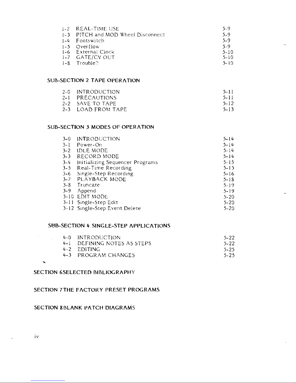
1-2 REAL-TIME USE
1-3
PITCH and MOD Wheel Disconnect
1-4
Footsw~tch
1-5 Overflow
1-6 External Clock
1-7
GATEICV OUT
1-8 Trouble?
SUB-SECTION
2
TAPE OPERATION
2-0 INTRODUCTION
2-1 PRECAUTIONS
2-2 SAVE TO
T.4PE
2-3 LOAD FROhl T.4PE
SUB-SECTION 3 MODES OF OPERATION
3-0 INTRODUCTION
3-1 Power-On
3-2 IDLE MODE
3-3 RECORD MODE
3-4
ln~t~allz~ng Sequencer Programs
3-5
Real-T~me Recording
3-6 Single-Step
Record~ng
3-7 PLAYB4CK MODE
3-8 Truncate
3-9 Append
3-10 EDIT
hlODE
3-1 1 Slngle-Step Ed~t
3-12 S~ngle-Srep Event Delete
SUB-SECTION
4
SINGLE-STEP APPLICATIONS
4-0 INTRODUCTION
4-1 DEFINING NOTES
.4S STEPS
4-2 EDITING
4-3 PROGRAM CHANGES
.
SECTION 6SELECTED BIBLIOGRAPHY
SECTION 7THE FACTORY PRESET PROGRAMS
SECTION
8BLANK PATCH DIAGRAMS
GETTING STARTED
14
INTRODUCTION
The Prophet-10 contains two completely programmable polyphonic synthesizer banks, each having five
complete and individual synthesizer "voices." Although each voice
is
keyed independently,
all
five
voices in each polyphonic bank function from the same patch setting, and are therefore homophonous.
However, each of the two 5-voice synthesizer banks can operate on
a
completely different program,
and can be articulated independently via the two keyboard manuals. In other words, two different
programs can be used
at
any one time. One
is
the UPPER program, with one 5-voice synthesizer usually
tied to the upper keyboard, and the other
is
the LOWER program, with the other 5-voice synthesizer
usually
tied to the lower keyboard.
Each synthesizer voice consists of two voltage-controlled oscillators
(VCOs), a white noise source,
a
resonant low-pass voltage-controlled filter (VCF), a voltage-controlled amplifier (VCA), two envelope
generators (one wired to the VCF and one wired to the VCA) and
a
3-band equalizer (EQ). In addition,
there are routings (via the POLY-MOD section) that allow for oscillator
B and the filter envelope
generator
lo lunction as modulation sources which can be applied to the frequency or pulse-width of
oscillator A, or the filter frequency. Finally, each 5-voice synthesizer bank has a single LFO which can be
applied to
all
of
its
voices for various effects. The two LFOs (UPPER and LOWER) can also be combined
(summed) and applied to both polyphonic synthesizers for other effects.
The Prophet also contains a microcomputer, which serves several purposes: it determines which voice
is
assigned to which key, it keeps the voices in tune, and (most importantly) it remembers preset voice
patches
which may be instantly recalled to program the voices. These preset programs are retained by
the microromputer's memory even when the Prophet
is
turned off, thanks to a small battery with
a
10-year life.
-
1-1
SET-UP
To set up the Prophet-10, simply plug the power cord into an AC outlet and connect the instrument to
an amplifier via the AUDIO OUT jacks on the back panel. Both balanced (XLR connector) and
unbalanced
('A"
phone jack) outputs are provided. The MONO jack provides the output of
all
ten
synthesizer voices. The UPPER and LOWER jacks can be used to separate the outputs of the two
polyphonic synthesizer banks for stereo effects.
The fixture for the removable power cord also contains the main AC fuse, facilities for selecting
between
100,120,220, and 240 volts AC line levels, and an AC line filter. Prophet-10s shipped in the USA
will be set
at
120, those shipped to Europe will be set
at
220, and those shipped to Japan will be set at 100.
The fuse used should match the AC setting: A 2-amp slo-blo fuse should be used for 110 and 120-volt
operation, and
a
1-amp slo-blo fuse should be used for 220- and 240-volt operation. (These
specifications are indicated on the power cord fixture.)
As with most electronic equipment, the Prophet comes with a three-prong power plug to insure safe
grounding with other pieces of equipment in use. The ground prong
is
connected to the chassis of the
instrument. It
is
up to you to check the ground connections of the Prophet and all other instruments
and equipment you use, to prevent potentially lethal shocks. As you probably know, many older
bulldings and clubs are not known ior their quality AC wiring, so we urge you to use one of the several
"ground-checking" devices available on the market to verify AC connections.
Because of the AC ground, a "ground loop" will often exist when a cable
is
plugged between the
i
Prophet and an amplifier; as a result, low-level hum will often occur. Defeating the
AC
ground with a
two-prong adapter will usually eliminate the
nolse, but
it
can also set up a shock hazard between the
-
pieces of equipment. The amount of hum
is
dependent on where the two units are connected to AC.
For minimal hum, use the same outlet for both the Prophet and
its
amplifier: with this set-up, the hum
will be low enough below the signal level to be acceptable. The further away from each other the plugs
are connected to AC, the more hum will occur. The quality of wiring in the wall and wall socket will also
affect the amount of hum,
Here
is
a
summary of recommended procedures to follow when setting up the Prophet-10:
1) Plug the Prophet into
a
three-prong cutlet. Don't dcfeat he AC-ground.
2)
Plug all other connected equipment (amplifiers, volume pedals, effects devices, and other
accessories) into the same outlet. (Warning: do not overload. When in doubt, consult an
electrician.)
3)
Verify all equipment grounding with a ground tester.
Sequential Circuits
is
nor responsible for any equipment failure due to incorrect ACconnections, and
is
not liable for any personal injury due to electrical shocks as a resulc of poor grounding.
1-2
TURN-ON AND INITIAL TUNING
The Prophet
is
turned on via the POWER switch on the rear panel. After the instrument
is
turned
on, the front panel will be dark
-
except for the TUNE switch - for approximately 15 seconds
while the computer tunes the oscillators. When tuning
is
complete the front panel will light up
and the BANK-PROGRAM indicator (the digital display) in the PROGRAMMER section of the front
panel will display
"1-1"
for both the UPPER and LOWER programming sections. This indicates that
the Prophet-10
is
ready to play and that
its
voices are programmed according to the settings stored
in those locations in the computer's memory. In addition, the UPPER panel switch in the programming section will be lit, indicating that the UPPER program
is
displayed on (and connected
to) the front panel patch controls. (Although separate UPPER and LOWER programs can be used
at
any tme, there
is
only one set of front panel controls. Hence, only one of the two programs can
be connected to the front panel controls at
a
time.)
1-3
MASTER OUTPUT CONTROLS
The MASTER VOLUME knob
is
used to adjust the overall volume of the Prophet-lo's output.
The BALANCE knob
is
used to adjust the relative volume of the upper and lower synthesizer banks
The A40 switch activates
3
built-in, crystal-referenced A-440 oscillator which
is
accurate to .1 Hz
in any environment. This reference oscillator
is
enabled by hitting the switch - the LED indicator
in the switch will light. To turn the tone off, hit the switch again. (The
A-440 signal
is
routed
independently to both the upper and lower synthesizer banks. In order to be heard, the programmable VOLUME, MASTER VOLUME, and BALANCE knobs must all be set correctly
-
as
well
as any AMP footpedals.)
The MASTER TUNE knob
is
used to adjust the overall tunlng of the Prophet-lo's output. Tune by
holding down
a
key (e.g. middle A) and match~ng either the A40 reference or an outside pitch
source.
14
PRESET SELECTION
When turned on, the Prophet automatically enters PRESET mode, meaning that
it
is
ready to set
up the synthesizer's voices according to preset patches stored in the memory of the Prophet's
computer. Both the UPPER and LOWER presets are arranged in four banks of eight programs each
(UPPER
=
32 programs, and LOWER
=
32
programs, for a total of
64
programs). These programs
may be selected via the switches in the programmer section on the front panel. The switches
marked BANK SELECT will step through the banks in order, and the two sets of eight switches
marked PROGRAM SELECT (numbered
1
through
8)
allow immediate selection of a particular
program within
a
bank. To choose a program for either the UPPER or LOWER polyphonic
synthesizer bank, step through the banks
unt~l you reach the bank you want, then hit the
PROGRAM SELECT switch for the
exact program you wish. The selected bank will be indicated by
the digital display in the programmer section, and the selected program will be indicated both by
the digital display and by
the LEDs embedded in the PROGRAM SELECT switches. You will be able
to see which program
is
selected for both the UPPER and the LOWER synthesizer bank. The
PANEL select switches will allow you to choose which of these two programs you wish to have
displayed on (and connected to) the front panel patch controls.
Since the Prophet
is
shipped with a full complement of
64
factory programs
it
will be ready to
play
as
soon
as
it
has been turned on and the initial tuning procedure has ended. For information
on these factory-loaded patches, see SECTION
7,
THE FACTORY PRESET PROGRAMS. For
information on MANUAL operation, see SECTION 3, THE PATCH CONTROLS.
1-5
PITCH AND MOD WHEELS
The pitch wheel (PITCH) and modulation wheel (MOD) are located to the left of the upper
keyboard. Normally, both wheels affect
all
voices simultaneously. The PITCH wheel has a center
detent position, from which the pitch may be varied up or down
by
about a 5th. Both wheels can
be "disconnected" from the LOWER program by holding the LOWER TRANSPOSE DOWN switch
and hitting
the LOWER TRANSPOSE UP switch. Repeating this procedure will re-connect the
wheels. This
is
useful when using the poly-sequencer.
The MOD wheel determines, for the most part, the amount of modulation to be routed via the
MON~MOD
settings of a particular program. The total amount of modulation to be routed
is
determined by the sum of the settings of:
1)
the programmable LFO AMOUNT knob in the
MOW-MOD section on the front panel; 2)
the MOD wheel; and 3) the voltage supplied from
PEDAL
1
(if
it
is
programmed to affect the MONO-MOD section). Note that the MOD wheel may
have different results on the upper and lower programs, since the MONO-MOD sections may be
programmed differently. For information on the effects that may be engaged via the MOD wheel
relative to the various factory-programmed patches, see the notes accompanying each patch
diagram in SECTION
7.
1-6
TRANSPOSE SWITCHES
These switches allow instant octave transposition of either UPPER or LOWER programs, within an
overall four-octave range. Each touch of the switch will raise or lower the program
by
an octave.
The relationship between this overall range and the TRANSPOSE switches
is
determined by the
settings of the FREQUENCY knobs in the oscillator sections of the front panel. These knobs also
have
a
four-octave range; and
if,
for instance, both oscillators were set
at
the top of their
frequency range in
a
particular program, the TRANSPOSE UP switch would have no effect (the
TRANSPOSE DOWN switch would in this case have
a
four-octave range). In addition, the
TRANSPOSE switches always operate to the limit of
the~r range.
If
you begin with a program that
has the
osc~llators tuned an octave apart, and continue to hit the TRANSPOSE UP switch, both
oscillators will end up in unison
at
the top of their range.
The computer remembers the number ol times you strike a particular TRANSPOSE switch, even if
it
has ceased to have an effect on the oscillators. Here
is
an example of what this means in actual
use: You begin with both oscillators set two octaves up (with their respective FREQUENCY knobs);
then you hit the TRANSPOSE UP switch five times. The
last
three strokes will no longer transpose
the oscillators, but the computer
is
still
counting, so in order to transpose down again, you will
have to hit the TRANSPOSE DOWN switch three times before anything happens. On the fourth
stroke the oscillators will transpose down an octave.
If the KEYBOARD switch on OSCILLATOR B
is
off, the TRANSPOSE will have no effect on that
oscillator. OSCILLATOR A will always be affected.
If the KEYBOARD switch in the FILTER section of the patch panel
is
lit, the TRANSPOSE switches
will also connect to the CUTOFF FREQUENCY of the
filtet. Since this c>aran,eter has a much
greater range than that of the oscillators
(10
octaves), successive strokes of the TRANSPOSE
switches may continue to alter the CUTOFF setting after the oscillators have reached the limit of
their range.
None
ol the transpose operations performed with the TRANPOSE switches can be recorded
as
part
of
a
program. In order to change octaves permanently, you must adjust the FREQUENCY controls
on the oscillators (and perhaps the CUTOFF control on
the filter).
To return quickly to the original programmed octave after transpositions via the TRANPOSE
switches, simply hit the PROGRAM switch for the program you are playing or change to
a
new
program. (Adjusting either FREQUENCY knobs will also cancel the effects of the TRANSPOSE
switches.)
1-7
VOICE
ASSIGNMENT
The assignment of voices to keys played on the keyboard
is
done by the Prophet's computer. If the same
key
is
struck repeatedly, the computer will continue to assign the same voice. If more than five keys are
held down
at
the same rime on either keyboard in NORMAL keyboard mode, the computer will
reassign the earliest used voices first; for example, playing C,
D,
E,
F,
G,
and A in succession and holding
all
six
keys down will cause
D,
E, F,
G,
and A to be sustained -the C will disappear when theA
is
played.
In other words, the Prophet normally operates on
a
"last-note priority" system: each new note played
is
assigned to the earliest-used voice. In DOUBLE keyboard mode, reassignment will begin
if
more than
five
kys
are held down (total) on both keyboards. In SINGLE and ALTERNATE keyboard modes
reassignment will occur if more than ten keys are held down on both keyboards.
There are two exceptions to this system. First,
if
the UNISON switch
is
on, all five voices are assigned
to'a single key. UNISON assigns priority to the highest key held. This
is
particularly useful in DOUBLE
keyboard mode. (In UNISON mode. the keyboard operates in single trigger fashion: there will not
be
a
new trigger unless there is a space between key depressions.)
The second exception to normal voice assignment is provided for the occasion when
a
voice may
become"unplayable" due to component failure. In such cases, a VOICE DEFEAT allows you to eliminate
the bad voice from the assignment system. The Prophet can then be played normally, with the
remaining voices. The
VOlCE ASSIGNMENT lights allow you to see which voice
is
failing.
To defeat a voice, hold the key currently assigned to
it
with one hand while holding UPPER PROGRAM
SELECT
1
and pressing UPPER PROGRAM SELECT 8 with the other hand. The voice will be defeated,
the corresponding light will go out, and the voice will remain defeated until the Prophet's power
is
switched off.
Defeating a voice in one synthesizer bank will also defeat the corresponding voice in the other bank.
For instance, defeating voice
4
in the UPPER synthesizer will also defeat voice 9 in the LOWER
synthesizer.
If
power is turned olf, then on again - the voice will have to be defeated again
(if
it
is
still
bad).
1-8
RETUNING
Although the computer tunes the oscillators when the Prophet
is
first turned on,
it
may become
necessary
to retune, particularly during the first few minutes of operation since the oscillators need time
to stabilize. After
20
minutes or so the instrument should not have to be retuned very often, unless there
is a radical temperature change in the room.
Hitting the TUNE switch will tell the computer to retune the oscillators. When this
is
done the front
panel will go dark
-
except for the TUNE switch - for approximately
15
seconds, and then will return
to the previous front panel status.
SECTION
2
BASIC PROCEDURES
2-0
INTRODUCTION: THE FRONT PANEL
The Prophet-lo's front panel controls are color-coded to clarify the modes of operation and the funnion
of the computer's memory. All black knobs and switches are programmable; that
is,
their settings can be
recorded into memory and recalled in PRESET mode.
The silver knobs (MASTER VOLUME, BALANCE, and MASTER TUNE) and grey switches (PRESET, A-440,
TUNE, and TRANSPOSE switches, and the entire PROGRAMMER section) are not programmable. The
PITCH and MOD wheels are also not programmable. The RECORD switch
is
orange, so that
it
can easily
be distinguished.
All of the switches except BANK SELECT and TRANSPOSE have LED indicators embedded in them. And,
except for the two sets of
8
PROGRAM SELECTS, PANEL, KEYBOARD MODE, and TUNE,
all
LED
switches are alternate action: one push turns them on, the next push turns them off. For example, the
PRESET switch LED when lit indicates PRESET mode. The LED goes off when the Prophet
is
switched to
MANUAL mode, by pushing the (lit) PRESET
switch.
2-1
MODES OF OPERATION
In PRESET (PRESET switch LED
lit)
the Prophet-lo's synthesizers will be patched according to the
programs stored in the locations indicated on the digital display. In this mode, entire patches can be
changed instantaneously using the BANK SELECT and PROGRAM SELECT switches in the programmer
section.
In addition to PRESET, the Prophet has MANUAL and RECORD modes of operation. In MANUAL mode
a parch can be formed entirely "from scratch." RECORD
is
a
momentary mode for storing or relocating
programs. A "patch" becomes a "program" when recorded. Custom programs can therefore by created
h
two ways:
1)
by recording manually-formed patches or
2)
recording edited programs. (Edited
programs can be recorded into the original location
if
the original program
is
not desired, or into a
new location.)
In MANUAL mode the control panel always indicates the status of the patch under construction. You
can see exactly what signal paths are closed by (lit) switches. The knob settings reflect their actual values.
As you select different programs in PRESET the switch
LEDs
still
indicate how the switches are
programmed. Note that the knobs cannot move with program changes, but stay where they were
last
set. So, in PRESET the knobs do not normally indicate their "current" setting. However
as
soon as you
move a knob to
EDlT a program, that knob converts to MANUAL operation. So only the knobs you
move will actually indicate their current setting: the parameters controlled by unmoved knobs do not
change.
This
EDlT feature of PRESET mode
is
a
powerful tool that allows you to experiment with changes in
programs,
uslng the patch controls. The original program remains unchanged and can be restored
at
any time by s~mply hitting
its
PROGRAM SELECT again.
For example, suppose you like program
3-3
but want to change OSC A pitch and prefer a brighter tone.
In PRESET mode, select BANK
3
-
PROGRAM
3,
adjust OSC A FREQUENCY to the desired pitch and
increase the FILTER CUTOFF to the desired brightness. You can cancel any changes and return to the
original program by hitting PROGRAM SELECT
3.
If you want to permanently change program
3-3
to
your edited version, record
it
in
3-3.
Or,
if
both the original and edited versions are wanted, record the
edited program in
a
new location. Remember that even though two programs (UPPER and LOWER) can
be selected
at
a
time, only the program indicated by the PANEL select switches can be altered via the
front panel patch controls. However, edited changes are remembered when the UPPER and LOWER
PANEL switches are hit. Hence, one can select UPPER and edit the UPPER program, and select LOWER
and edit the LOWER program independently
as
desired. Both programs will play in their edited form,
even if you switch back and forth
a
number of times.
NOTE
-
If a particular patch
is
programmed with the RELEASE switch off bur with a pr,grammed
amplifier envelope RELEASE setting that will have an audible effect, this release can be engazed (while
in PRESET mode) by switching the RELEASE switch on, or using the footswitch. Further modifications
(non-permanent changes) to the preset programs can be brought about through the use of other
accessories which connect to the Prophet via jacks in the back panel. For information on these
possibilities, see SECTION 4 ACCESSORIES. Remember that the RELEASE switch and knob settings may
be different on the upper and lower programs. Hence, the footswitch may have an effect on one
program and not the other depending on the different settings.
2-2
RECORDING PROGRAMS
In general, to record a manually-formed patch or edited program, the RECORD switch
is
pressed on,
then the desired destination BANK and PROGRAM are selected. NOTE
-
To protect existing programs,
RECORD mode can only be entered
if
the back panel RECORD ENABLE/DISABLE switch
is
up
(ENABLE). It
is
suggested that the switch be left in the DISABLE position until the modes of operation
and control tunctions are understood. This will prevent the accidental erasure of the factory preset
programs (Remember also that an accidental erasure
is
not a disaster, since by referring to the diagrams
in SECTION
7
you can always patch a factory program manually, and re-record
it).
The &act RECORD procedure
is
as
follows:
1)
Set
the back panel RECORD ENABLE/DISABLE switch to the ENABLE (up) position
2)
Switch on the orange RECORD switch in the PROGRAMMER SECTION.
9j
Select the desired general location (UPPER or LOWER) by using the PANEL select switches
4) Select the desired bank using the BANK SELECT. (Ignore this step
if
current BANK
is
desired)
5)
At this point you can abort RECORD mode by switching the RECORD switch off. The memory will
not be affected.
6)
Otherwise, pressing any PROGRAM SELECT will cause the patch or edited program to be recorded
at
the corresponding location in the selected bank. NOTE - Make sure to hit the correct PROGRAM
SELECT switch or you may erase a program you wanted to keep.
7)
When a PROGRAM SELECT switch has been hit, the RECORD switch LED will automatically go off
and the Prophet will return to the mode it was in before recording.
8)
After recording a patch
it
is always a good idea to return to PRESET mode and check that the program
-
is
correctly recorded in the desired location.
To move a program from one location to another (edited or not), the procedure
is
as
follows:
1) Select the program to be moved (set PANEL, BANK. PROGRAM)
2)
Edit the program (if desired)
3)
Hit RECORD switch (latches up current program).
4)
Change PANEL
if
necessary (lor moving from UPPER to LOWER or vice-versa)
5)
Select destination BANK
(if
necessary)
6)
Hit desi ed PROGRAhl SEL ICT
7)
This new location now has the old program stored in
it.
In order to play the program,
it
is
necessary
to hit the PROGRAM SELECT
a
second time to "load" the program.
2-3
KEYBOARD MODES AND THE UPPER/LOWER PANEL SWITCHES
The four programmable KEYBOARD MODE switches are an important part of the basic operation of
the
Prophet-10, since they determine the relationship between the two 5-voice polyphonic synthesizers
and the two keyboard manuals. They offer a great range of possibilitiesfor playing the programsstored
in the Prophet's UPPER and LOWER program sections.
NORMAL Mode: The UPPER five voices (connected to the UPPER program) play on the upper
keyboard, while the LOWER five voices (connected to the LOWER program) play on the lower
keyboard.
SINGLE Mode: All ten voices will be assigned and will play their own UPPER or LOWER program.
Usually the UPPER and LOWER programs are set up to be the
same. The notes can be played on either
keyboard in any combination.
DOUBLE Mode: Hitting
a
key (on either keyboard) will engage one voice with the UPPER program and
one voice with the
LOWER program. Only five keys can be played
at
one time (since each key
is
connected to bofh of the 5-voice synthesizer banks).
ALTERNATE Mode: Every new key hit will alternate between the UPPER and LOWER programs.
As can be seen, NORMAL
is
the only mode in which
it
makes a difference which keyboard
is
physically
p?ayed. In the other three modes the keyboards can be used interchangably - together or separated.
So, these switches determine how the Prophet-10 will be played. There
is
also another factor in setting
up the playing
modeof the instrument: thechoiceof program being displayed on the front panel patch
controls. Since the KEYBOARD mode switches are programmable, their status
is
recorded along with
each patch. At any given time, there will be two selected programs (UPPER and LOWER), but the
KEYBOARD mode operation will be determined only by the program that
is
displayed on the front
panel patch controls. Therefore, the
UPPER/LOWER PANEL switches also play a role in determining the
playing configuration on the Prophet. For example, look at programs
U-1-1 and L-1-1 - both are
patches
with a brass sound.
If
U-1-1
is
displayed, the Prophet will operate in NORMAL keyboard mode,
but
if
L-1-1
is
displayed, the Prophet will operate in DOUBLE keyboard mode.
These interrelations can be used to enhance the flexibility of the Prophet-10
as
a live performance
instrument.
SECTION
3
THE PATCH CONTROLS
3-0
INTRODUCTION: THE FRONT PANEL
This section explains the functions of the
~atch controls comprising the "modules" (e.g. VCO, LFO,
VCF, and VCA) outlined on the front panel. The alternatives of each switch and ranges of each knob are
described relative to the overall signal flow of the voices and to the modulation circuitry.
In SECTION
1
and SECTION
2,
we described the basic operation of the Prophet using the factory
programs accessible
through the UPPER and LOWER PROGRAMMER.
It
is
true that the Prophet can
be used exclusively in PRESET mode, in which case the voice and modulation patch controls would
not be used very often. However
it
is
also true that using the instrument in this way would defeat
a
large part of
its
overall purpose, which is to allow synthesists to create and record their own programs
for immediate use. The creation of satisfying custom programs depends entirely on your familiarity with
the controls.
By the way, in describing the controls this section will not attempt to be
a
manual of synthesis
technique. However by referring to the parch diagrams in SECTION
7
while playing through the factory
programs, you will soon grasp some of the sonic possibilities the Prophet makes available. As explained
in SECTION
7,
we particularly encourage you to EDIT the factory programs (see paragraph
2-1,
MODES
Qf
OPERATION). This
is
the best way to gain familiarity with the patch controls.
For more information on synthesis technique, refer
ro the books and magazines listed in SECTION
6.
3-1
VOICE SIGNAL FLOW
The Prophet's audio output results from several stages of signal generation, combination, and
modification. The front panel
is
divided into VOICE and MODULATION sections. (MODULATION
controls are covered in paragraph
3-01. It should be kept in mind that although only one voice
is
depicted on the panel, the voice controls simultaneously patch five voices in parallel. The figure
diagrams signal flow in
a
single voice. Basically, the MIXER sets OSCILLATOR (VCO) A, B and NOISE
levels sent to the FILTER (VCF) and AMPLIFIER (VCA) where, roughly
speaking,the timbre and dynamics
are shaped. The EQUALIZER section further modifies the frequency spectrum. Then the voices of each
5-voice synthesizer bank are combined and their overall level and tuning are set by the VOLUME and
TUNE controls. Finally the two synthesizer banks are combined, and the instrument's overall level and
tuning are set by the MASTER VOLUME, BALANCE, and MASTER TUNE controls.
3-2
OSCILLATOR A
FREQUENCY knob: Controls pitch (oscillator tuning). Stepped (quantized) in semitones over
a
four-octave range. (Exact pitch
is
set with the MASTER TdNE knob.)
NOTE:
-0SC A pitch
is
always under keyboard control.
SAWTOOTH WAVESHAPE
switch:
When on, a sawtooth wave (containing
all
the harmonics)
is
supplied
as
OSC A's output.
PULSE WAVESHAPE
switch:
When on, a pulse wave
is
supplied
as
OSC A's output. Harmoniccontent
is
dependent on the setting of the PULSE WIDTH knob.
NOTES:
-When both the sawtooth and pulse switches are on, sawtooth and pulse waves are mixed at full level
(
-
and supplied
as
OSC A's output.
-When neither waveshape switch
is
on, no signal
is
supplied as OSC A's output.
PULSEWIDTH knob: Sets OSC A pulse width from approximately 1% to
99%.
(Varies harmonic content
of pulse output.)
NOTES:
-The extreme settings of this knob (0 and 10) may cause the OSC A signal to degenerate to DC,
resulting in no output signal (of course, this knob will only have this effect if the pulse waveshape
.
IS
selected).
-An exact square wave (having only odd harmonics) may be obtained by setting this knob to
approximately
5
and adjusting by ear for the drop out of the 2nd harmonic (the octave).
SYNC
switch:
when on, OSC A becomes"hard" synchronized to OSC B, and will therefore tune only
to harmonic frequencies of OSC B.
Intermediate frequency settings will produce unusual waveforms
(and therefore unusual timbres) at the next lower harmonicof OSC
B. To gain an understanding of the
effect of
SYNCing, check the following factory preset programs: 1-4,1-7,3-2, and U-4-3.
NOTES:
-When
a
pulse shape with a wide pulse width
is
selected for OSC A in sync with OSC B, and
if
OSC B's
frequency
is
set much higher than that of OSC A, the signal from OSC A may degenerate into
DC since the pulse
is
not given a chance to discharge before being re-synced.

3-3
OSCILLATOR
B
FREQUENCY knob: Controls pitch (oscillator tuning). Stepped (quantized) in semitones over a four
octave range.
(Exaa
pitch
is
set with the MASTER TUNE knob.)
NOTE:
-If the KEYBOARD switch
is
off, the FREQUENCY knob will have a range of nine octaves.
FlNE knob: Continuously varies pitch over a semitone range (up from the basic pitch setting of the
FREQUENCY knob). This knob is useful for detuning of OSC B relative to OSC A. When no detuning
is
desired, the FlNE knob should be set
at
0.
SAWTOOTH WAVESHAPE switch: When on, a sawtooth wave (containing all harmonics)
is
supplied
as
OSC B's output.
TRIANGLE WAVESHAPE switch: When on,
a
triangle wave (containing only odd harmonics)
is
supplied
as OSC B's output.
PULSE WAVESHAPE switch: When on,
a
pulse wave is supplied
as
OSC B's output (harmonic content
is
dependent on the setting of the PULSE WIDTH knob).
NOTES:
-
Wkn two or three of the waveshape switches are on, the selected waveshapes are mixed
at
full level
and supplied
as
OSC 0's output.
-
When no waveshape switch
is
on, no signal is supplied
as
OSC B's output. However, the overall pitch
range of
a
particular patch may
still
be determined by the FREQUENCY knob retting of OSC 0,
if
OSC
A
is
in SYNC with
it.
POLSE WIDTH knob: Sets OSC B pulse width from approximately 1% to
99%.
(Varies harmonic content
of pulse output.)
NOTES:
-The extreme settings of this knob
(0
and 10) may cause the OSC B signal to degenerate to DC,
resulting in no output signal (of course, this knob will only have this effect if the pulse waveshape
is selected).
-An exact square wave (having only odd harmonics) may be obtained by setting this knob to
approximately
5
and adjusting by ear for the drop out of the 2nd harmonic (the octave).
LO FREQUENCY switch: When on (with the KEYBOARD switch off), OSC B will function as a low
frequency oscillator (LFO), ranging from approximately
.4
Hz (or 2.5 seconds-per-cycle) into low audio
frequencies. This function
is
usually used in conjunction with the POLY-MOD section (see
paragraph
3-8).
KEYBOARD
switch:
When on, the frequency of OSC B
is
controlled by the keyboard. When off, the
frequency of
OSC
B
will not be controlled
by
the
keyboard.
NOTES:
-
If the KEYBOARD switch
is
off and the LO FREQ switch
is
off, OSC B will act
as
a drone in the audio
range. Set the pitch of this drone with the FREQUENCY knob after the KEYBOARD switch
is
turned
off (otherwise you may have to retune).
-The use of OSC
I3
as a modulation source for the POLY-MOD will be discussed in paragraphj-8.
Normally, when OSC B
is
being used
as
an audio signal source, the LO FREQ switch will be off and the
KEYBOARD switch will be
on.tfo4*Eep-eawkalmm-&iag~ams-
/e~a~~ec4oaded-kban!c?)-
3-4
MIXER
OSC
A
knob:
Determines the amount of OSC A's output sent to the filter
OSC B
knob:
Determines the amount of OSC B's output sent to the f~lter.
NOISE
knob:
Determines the amount of white noise (combination of all frequencies) sent to the filter.
.
NOTES:
-These mixer amount knobs are also used to program overall volume of the patch so that when
switching
from one program to another in PRESET mode one program won't be wildly different in
volume than the others.
CUTOFF knob:
The Prophet's filters are 4-pole, 24 dB-per-octave low-pass filters and therefore the
cutoff knob sets the frequency below which all elements of the signal are let through. The higher
frequency components of the signal
(i.e. the frequencies above the cutoff frequency) are suppressed.
The higher the knob
is
set, the more frequencies are allowed through the filter. In general terms, the
CUTOFF knob may be thought of as a tone control.
RESONANCE knob:
As the setting of this knob
is
increased from 0 to approximately
7,
the amount of
resonance ("emphasis", "regeneration", or
"Q")
applied to those signal frequencies at the cutoff
frequency will increase
(as
the resonance increases, the frequencies far below the cutoff frequency will
be less audible relative to
the frequencies being resonated). If the setting
is
increased beyond
7,
the filter
will break into oscillation and will act
as
a
sine wave audio source whose pitch
is
determined by the
cutoff frequency.
ENVELOPE AMOUNT knob:
The filter cutoff frequency may be contoured (shaped) electronically in
a
pattern determined by the settings of the AnACK, DECAY, SUSTAIN. and RELEASE knobs (these are the
controls for the ADSR envelope generator that
is
connected to the filter). The envelope amount knob
determines the amount (but not the shape) of this contouring that
is
applied to the filter's cutoff
frequ&cy.
NOTES on the ENVELOPE GENERATORS:
-The ADSR envelope generators whose controls appear
as
the AnACK, DECAY, SUSTAIN, and
RELEASE knobs in the filter and amplifier
senions generate voltage patterns
that
can be used to
.contour timbre (via the filter's cutoff frequency) and loudness (via the VCA, see paragraph
3-6)
respectively. The voltage patterns generated have four stages (one for each knob)
as
illustrated. The
entire contour pattern
is
initiated when a key
is
depressed and proceeds through the attack and
decay stages
at
rates determined by the settings of those knobs. The sustain level
is
determined by
the setting of the SUSTAIN knob, and
is
maintained
as
long
as
the key
is
held down. When the key
is
released the release stage
is
activated and proceeds at a rate determined by that knob.
-In the FILTER section, the ENVELOPE AMOUNT knob functions as an attenuator on the voltage
patterns from the filter's envelope generator. There
is
no comparable attenuator connected to the
VCA's envelope generator.
ENVELOPE
AMOUNT
(FILTER
ONLY1
TIME
.
.I
:-8
ATTACK TIME
:
DECAY TIME
:
RELEA~E
TlME
-I
LENGTH OF TlME THAT KEY IS HELD DOWN
AlTACK
knob: Determines the length of time
it
takes the envelope generator's contour to go from
0
level
(at
initial key depression) to maximum level.
DECAY
knob: Determines the length of time
it
takes the envelope generator's contour to go from
maximum level to sustain level.
If SUSTAIN
is
set at maximum then the DECAY knob setting
is
irrelevant.
SUSTAIN
knob: Determines the sustain level of the envelope generator's contour. Remember, this
is
a level setting, not a time setting; the sustain time
is
determined by the key being held down.
RELEASE
knob: Determines the length of time
it
takes the envelope generator's contour to drop from
the sustain level to
0
level after the key
is
released. If the key
is
released before the attack and decay
stages of the envelope are complete. the RELEASE knob setting will determine the length of time for the
\
-
contour to drop from its level
at
the time of key release to 0 level. If the sustain
is
set
at
0
and the attack
and decay stages are complete (while the key
is
still
depressed) then the release setting
is
irrelevant.
NOTES:
-The time range on the ATTACK, DECAY, and RELEASE knobs
is
approximately 1 millisecond to
30
seconds. Since the response to the knob
is
exponential, the durations
as
set on these knobs will not
be linear; for example, setting
5
on these knobs gives a period of approximately
'h
second.
-Remember that, for the FILTER only (not the VCA), the overall level of the envelope generator's
contour
is
determined by the ENVELOPE AMOUNT knob.
If
the envelope amount
is
set at 9 then the
.
envelope will have no effect on the filter's cutoff frequency.
KEYBOARD
switch: When on, the control voltage from the keyboard will be applied to the filter's
cutoff frequency (just
as
it
is
normally applied to the frequency of the oscillators). This patch maintains
the cutoff frequency at a constant level relative to the notes played on the keyboard, and therefore
creates
a
consistency of tone color over the entire range of the keyboard. When this switch
is
off, notes
played higher on the keyboard will have more of their overtones suppressed than notes played lower
on the keyboard; as a result, notes played in the higher register of the keyboard will be less bright
in tone color than those notes played in the lower register of the keyboard.
NOTES:
-If the filter RESONANCE
is
set so that the filter
is
in oscillation (i.e, generating a sine wave), then
switching the KEYBOARD switch on will allow the frequency of this sine wave to be controlled from
the keyboard. Unless
a
complex effect
is
desired when playing the filter's sine wave in this way, the
envelope generator setting will normally be set
at
0;
the ENVELOPE AMOUNT knob should also
be set
at
zero in this case (in order to maintain a steady response from voice to voice).
3-6
AMPLIFIER
The
AlTACK, DECAY, SUSTAIN, and RELEASE controls in the amplifier section determine the settings
for the
ampliiier's ADSR envelope generator. For details on the function of these knobs, see the
"NOTES on the ENVELOPE
GENERATOR" and the notes on the AnACK, DECAY, SUSTAIN, and
RELEASE knobs in paragraph
3-5.
3-7
EQUALIZATION
EOUaL12aTION
LOW HID
"10"
.
LOW
knob:
provides cut/boost facil~ties for lower frequency signals.
MID
knob:
provides cul/boost facilities for mid-,ange frequency signals
HIGH
knob:
provides cut/boost facilities for high frequency signals.
3-8
MODULATION
The Prophet provides two distinct modulation systems, MONOphonic-MOD and POLYphonic MOD.
Modulation involves a source and
a
destination; the destination
is
modulated (changed) in a pattern
determined by the source. The MONO-MOD system, diagrammed above, uses a low-frequency
oscillator (LFO) with sawtooth, triangle, and square waves
as
source material. Note that the UPPER
synthesizer bank provides
a
descending sawtooth wave
as
a modulation source, while the LOWER
synthesizer bank has an ascending sawtooth wave. These modulation sources can be routed to the
frequency and pulse-width of OSC
A
(FREQ
A,
PW
A),
the frequency and pulse-width of OSC B (FREQ
6,
PW
B),
the filter's cutoff frequency (FILTER), or any combination thereof.
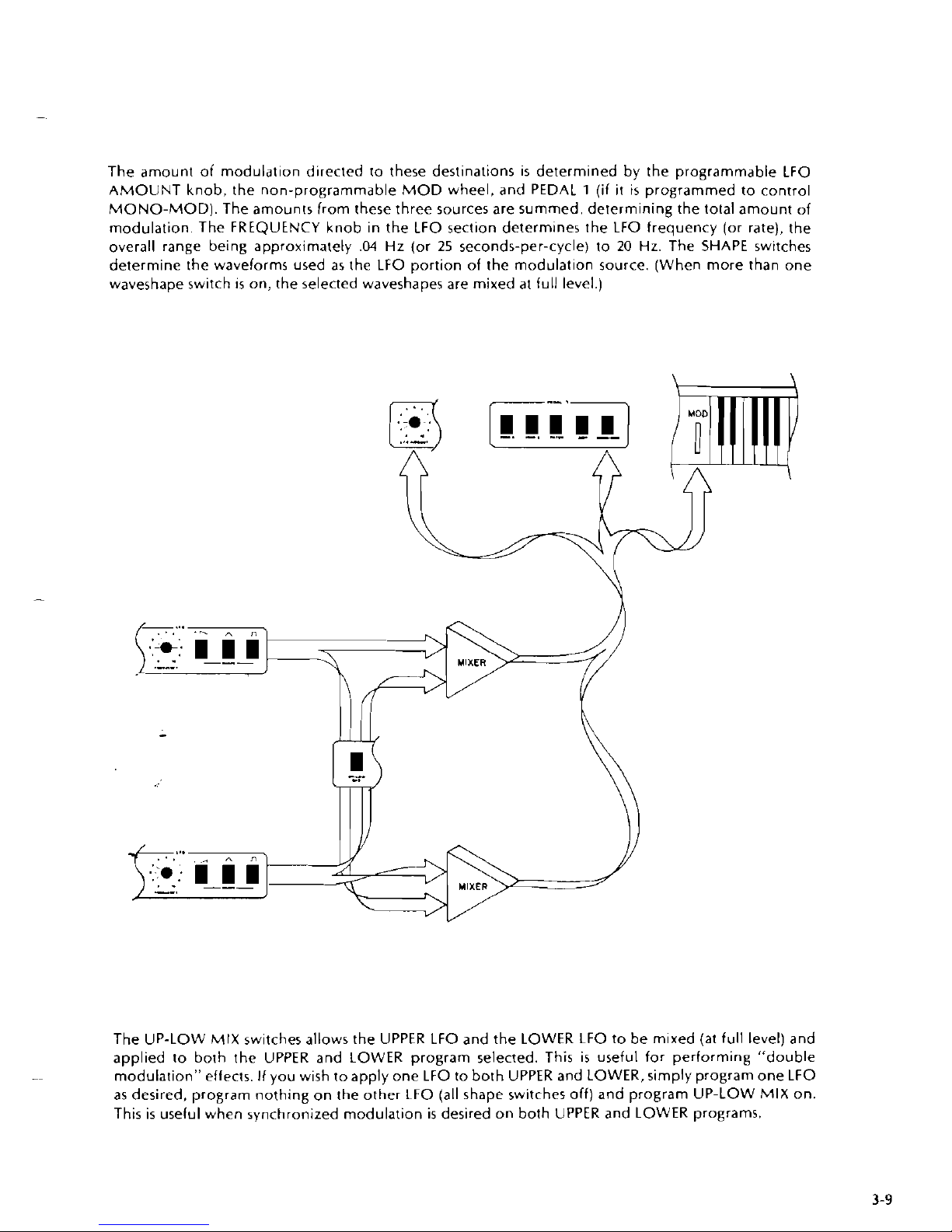
The amount of modulation directed to these destinations
is
determined by the programmable LFO
AMOUNT knob, the non-programmable MOD wheel, and PEDAL
1
(if
it
is
programmed to control
MONO-MOD). The amounts from these three sources are summed, determining the total amount of
modulation. The FREQUENCY knob in the LFO section determines the LFO frequency (or rate), the
overall range being approximately
.04
Hz (or
25
seconds-per-cycle) to
20
Hz. The SHAPE switches
determine the waveforms used as the LFO portion of the modulation source. (When more than one
waveshape switch
1s
on, the selected waveshapes are mixed at full level.)
The UP-LOW MIX switches allows the UPPER LFO and the LOWER LFO to be
m~xed
(at
full level) and
applied to both the UPPER and LOWER program selected. This
is
useful for performing "double
modulation" effects.
If
you wish to apply one LFO to both UPPER and LOWER, simply program one LFO
as desired, program nothing on the other
LFO (all shape switches off) and program UP-LOW MIX on.
This
is
useful when synchronized modulation
is
desired on both UPPER and LOWER programs.
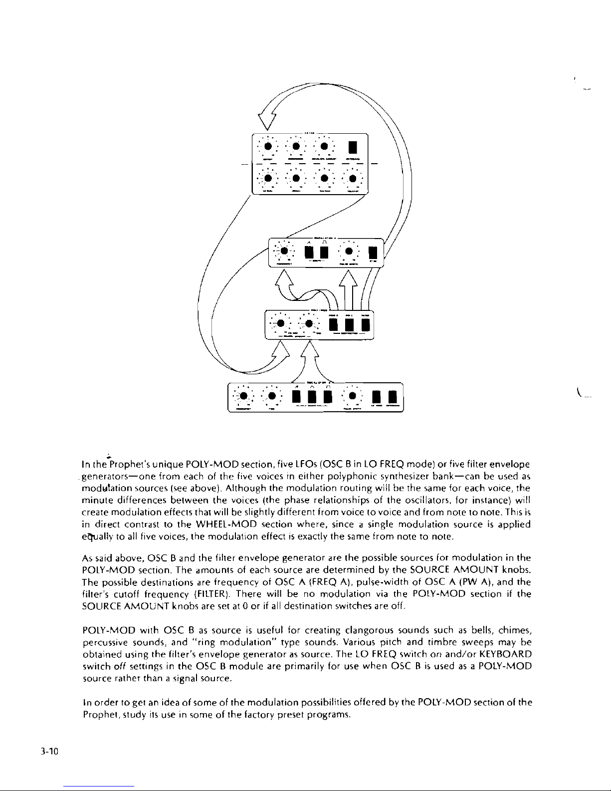
In the-prophet's unique POLY-MOD section, five LFOs (OSC Bin LO FREQ mode) or five filter envelope
generators-one from each of the five voices in either polyphonic synthesizer bank-can be used
as
modulation sources (see above). Although the modulation routing will be the same for each voice, the
minute differences between the voices (the phase relationships of the oscillators, for instance) will
create modulation effects that will be slightly different from voice to voice and from note to note. This
is
in direct contrast to the WHEEL-MOD section where, since a single modulation source
is
applied
e7pally to all five voices, the modulation effect
is
exactly the same from note to note.
As said above, OSC B and
the filter envelope generator are the possible sources for modulation in the
POLY-MOD section. The amounts of each source are determined by the SOURCE AMOUNT knobs.
The possible destinations are frequency of OSC A (FREQ A), pulse-width of OSC A (PW A), and the
filter's cutoff frequency (FILTER). There will be no modulation via the POLY-MOD section if the
SOURCE AMOUNT knobs are set
at
0
or
if
all destination switches are off.
POLY-MOD with OSC B
as
source
is
useful for creating clangorous sounds such
as
bells, chimes,
percussive sounds, and "ring modulation" type sounds. Various pitch and timbre sweeps may be
obtained using the filter's envelope generator
as
source. The LO FREQ switch on and/or KEYBOARD
switch
off settings in the OSC B module are primarily for use when OSC B
is
used
as
a POLY-MOD
source rather than
a
signal source.
In order to get an idea of some of the modulation possibilities offered by the POLY-MOD section of the
Prophet, study
its
use in some of the factory preset programs.
3-9
MISCELLANEOUS
RELEASE switch: When off, the amplifier and filter release times are approximately
0
(instant release).
(Actually, the release time
is
set at about 2 when the RELEASE switch
is
off, so there won't be an audible
"whack" when the key
is
released - which would be caused
by
the instantaneous closing down
of the VCA).
NOTES:
-This switch must be off to allow for the operation of the RELEASE footswitch (see SECTION
4
ACCESSORIES).
-Remember that this switch
is
separately programmable for UPPER and LOWER programs, €fen
though only one setting
is
visible. This
is
important relative to the use of the RELEASE footswitch.
DRONE switch: When on, the amplifiers on
all
voices (within the programmed synthesizer bank) will
stay
on for continuous sound once they are engaged via the keyboard.
If
the SUSTAIN in the AMPLIFIER
section
is
set to zero, you will not get a drone effect.
UNISON switch: When on, the Prophet will assign
all
five voices (within the programmed synthesizer
bank) to the highest played note. In other words, in UNISON mode the Prophet becomes
a
very
"fat"
monophonic synthesizer.
GLIDE knob: Effective only in UNISON mode, this knob
determines
the rate of gl~de (portamento)
between notes played on the keyboard.
NOTES:
-Remember that these controls are programmed separately for the UPPER and LOWER synthesizer
banks. Only one program status will be visible, but both will be operative.
-
In UNISON mode the svnthesizer bank will function on a hiah-note prioritv svstem. This
is
useful for
DOUBLE mode
lead-li~e-plus-chord effects. (UPPER
in
UNISON:
LOWER
program not in
UNTSON).
TUNEknob: For detuning one synthesizer bank relative to the other; will vary pitch continuously over
a
semitone range (up from the basic pitch setting of the oscillators].
If
no detl~ning
is
desired, the TUNE
knob should always be set
at
0.
VBLUME knob: For setting the overall level of programs relative to one another within one synthesizer
bank. This will allow for equal volume levels from program to program within
a
given series
of programs.
NOTES:
-If the MIXER, EQUALIZATION, and VOLUME knobs are all set
at
full level, the synthesizer may
distort. There are many levels of volume control on the Prophet-10, and they should be used
judiciously.
PEDAL
1
&
PEDAL
2:
These programmable switches allow for the routing of two external control
volrages to various destinations, (The Prophet-10
is
shipped with two pedals for this purpose, but other
voltage sources may be used
as
well; see SECTION
4,
ACCESSORIES.) PEDAL 1 may be routed to the
FREQUENCY of OSC A (FREQ A), the FREQUENCY of OSC
B
(FREQ
B),
the CUTOFF frequency of the
filter (FILTER), the VCAs (AMP). the MONO-MOD section, or any combination of the above. PEDAL
2
may be routed to the CUTOFF frequency of the filter (FILTER, the VCAs (AMP), or both. The amount of
voltage applied to these sources will be determined by the position of the pedal (or by the
outpur of any
other control-voltage device used).
NOTES:
-Remember once again that the routings for these pedals can be different for the UPPER program and
the LOWER
prlgram: the sar,ie pedal could have an entirely different function, depending on which
keyboard man
~al
you play (and on which keyboard mode you are on). Only one routing will be
displayed, but both the UPPER and LOWER routing will be functional.
-
If you do not plan to connect the pedals to the Prophet-10, it
is
best to program
all
of these switches
off.
If rhe AMP switch
is
engaged for either pedal and no pedal
is
plugged in, the VCAs for (hat
rynthesizer bank will remain closed and no sound will come from (he insrrument.
SECTION
4
ACCESSORIES
AND THE BACK PANEL
44
INTRODUCTION
The Prophet-10
is
shipped from the factory with two foot pedals and two foot switches,
all
of which can
be connected to the instrument via the back panel to provide many different kinds of nuance control
over the output of the synthesizer
bank5 Other interface capabilities are also provided, which may be
used
if
desired to create even more external control.
4-1
CONTROL VOLTAGE IN - PEDALS 1 AND
2
The two voltage pedals shipped with the Prophet are connected to
ir
via the two
'A"
jacks labeled CV IN.
The routings of these two pedals are determined by the programmable switches on the front panel
labeled PEDAL 1 and PEDAL
2
(see SECTION 3, paragraph 3-9). These voltage pedals are the most
common devices for use in this context, but various other devices (such as
a
ribbon controller, and
x/y
joystick controller, or a sample-and-hold module) will also provide for control of various interesting
effects. All voices within
a
given synthesizer bank will be affected equally by the input voltages. Note
that these inputs are
nor calibrated
at
1 v/octave.
The
'2
jack labeled RELEASE allows for footswitch control of the release portion of the filter and
amplifier envelope generators.
It
functions in much the same manner
as
the RELEASE switch on the
front panel. and is only operative when the RELEASE switch
is
off. It then takes the place of the RELEASE
switch: when pushed, the programmed amplifier release time
is
engaged; when not pushed, the
programmed amplifier release time
is
not engaged. In that respect,
ir
is
similar to a piano sustain pedal.
The footswitch for use in this context comes standard with every Prophet-10.
.
The
'A"
jack labeled PROGRAM INCREMENT can be used to step through the programs in a particular
program bank (both UPPER dnd LOWER) while both hands are engaged in other performance activities.
Each time the footswitch
is
depressed, both the UPPER and LOWER programs will increment one
position. This will most often be used to increment from one set of conceptually-linked programs to
another
(e.g., U-1-1 and L-1-1 would increment to U-1-2 and L-1-2), but the increment switch will work
on both program banks regardless of their relative position
(e.g., U-1-3 and L-2-4 would increment to
U-1-4 and L-2-5).
If
the currently selected program
is
an
8,
the increment footswitch will cycle back to 1
(U-1-8 would increment to U-1-1). The increment footswitch will never change banks;
it
will only cycle
through
the eight programs of the selected bank (for both UPPER and LOWER programs). The
footswitch for use in this context comes standard with every Prophet-10.
The
?4"jack labeled SEQUENCER
is
for use in connection with the optional POLYPHONIC SEQUENCER.
It serves the same function
as
the STOP/CONTINUE switch on the sequencer's front panel. Its function
will be described in SECTION
5
POLYPHONIC SEQUENCER.
4-3
MONOPHONIC SEQUENCER INTERFACE
i
The four1/." jacks in the SEQUENCER section of
the
back panel (VOLTAGE IN. GATE IN, VOLTAGE OUT,
-
GATE OUT) are provided to allow for the interfacing of a Sequential Circuits Model 800 digital
sequencer to the Prophet-10. The Prophet, when connected to
a
Model 800, devotes voice 5 of the
UPPER synthesizer bank to the sequencer; the other four voices of the UPPER synthesizer can be played
"live" while the sequencer is controlling voice
5.
NOTE: When a Model 800
IS
connected ro
a
Prophet-10 and
is
therelore controlling voice
5,
the corresponding voice on the LOWCR synthesizer,
voice
10,
will bedisabled Even
if
the keyboard
is
in DOUBLE mode, the sequencer will only play voice
5
-voice 10 will be disabled whenever the Model 800
is
connected to the Prophet-10.
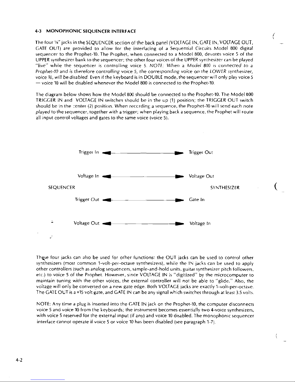
The diagram below shows how the Model 800 should be connected to the Prophet-10. The Model 800
TRIGGER IN and VOLTAGE IN switches should be in the up (1) position; the TRIGGER OUT switch
should be in the
renter
(2)
positi(8n. When reccrdint; a sequence, the Prophet-10 will send each note
played to the sequencer, together with
a
trigger; when playing back a sequence, the Prophet will route
all
input control voltages and gates to the same voice (voice
5).
Trigger In Trigger Out
Voltage
In
1
Voltage Out
SEQUENCER SYNTHESIZER
Trigger Out
4--
--
Gate In
-
Voltage Out
4
C
Voltage In
Thqe four jacks can also be used for other functions: the OUT jacks can be used to control other
synthesizers (most common 1-volt-per-octave synthesizers), while the IN jacks can be used to apply
other controllers (such
as
analog sequencers, sample-and-hold units, guitar synthesizer pitch followers.
etc.) to voice
5
of the Prophet. However, slnce VOLTAGE IN
is
"digitized"
by
the microcomputer to
maintain tuning with the other voices, the external controller will not be able to "glide." Also, the
voltage will only be converted on
a
new gate edge. Both VOLTAGE jacks are exactly 1-volt-per-octave.
The GATE OUT
is
a
+15 volt gate, and GATE IN can be any signal which switches through
at
least
3.5
volts.
NOTE: Any time
a
plug
is
inserted into the GATE IN jack on the Prophet-10, the computer disconnects
voice
5
and voice 10 from the keyboards; the instrument becomes essentially two 4-voice synthesizers,
with voice
5
reserved for the external input (if any) and voice 10 disabled. The monophonic sequencer
interface cannot operate
if
voice 5 or voice 10 has been disabled (see paragraph 7-71.
POLYPHONIC SEQUENCER OPERATION MANUAL
SUBSECTlON 1
BASIC OPERATION
1-0 INTRODUCTION
The Model
1015 Polyphonic Sequencer within the Prophet-10 uses the storage capabili-
ties of
a
second microcomputer system to allow you to directly record and edit your
own instrumentals. It allows ten-voice polyphony, a 2600-note capacity, wide range of
playback speed and of transposition, "multi-track" editing, operation in either RealTime or Single-Step modes, recordable
synthesiz-r program selections, and permanent
storage of sequences and synthesizer programs on digital cassettes.
You probably already know that when you play the Prophet-10, you are actually
providing "data" to a microcomputer which in turn controls the synthesizer voices. The
basic idea of
real-t~me sequencing is fairly simple. Basically, the Sequencer contains
a
clock, microprocessor, and memory. The clock generates 50 to 500 pulses per second
(Hz) as adjusted by the SPEED knob. To record, every time
a
clock pulse occurs the
microprocessor obtains from the Prophet-10 data signifying what keys are being held on
the Lower keyboard. By comparing each keyboard "sample," the microprocessor
discovers what keys are going on and off. It records in memory the number of the clock
pulse (or, step) at which each event
(a
note going on, or
off,
or a program change)
occurs. For playback, the microprocessor counts elapsed clock pulses and brings each
1
event out of memory as the clock count matches the sequence step numbers. The
microprocessor converts each event from memory into the same type
of
keyboard
sample data which it received and sends it to back to the Prophet. The Prophet's
computer interprets this data just as
if
it were the original "live" data from its own
Lower keyboard.
The Polyphonic Sequencer, then, substitutes for the lower keyboard which is in turn
programmed by the Prophet-10's KEYBOARD MODE controls. If keyboard mode is
NORMAL, the Sequencer
will drive only the Lower five voices programmed by the
current Lower program. The Upper manual can then be used "live." If the mode is
SINGLE (and the Upper and Lower programs are identical), the Sequencer will be able
to play up to ten notes at once.
If
in DOUBLE mode, the Sequencer will simultaneously
drive both the Upper and Lower voices to the five-voice limit. In ALTERNATE mode,
the Sequencer
will alternately assign up to ten notes at once to the Upper and Lower
voices.
Unlike the Prophet, the Sequencer memory does not save its contents when power is
turned off. The digital cassette deck is used for permanently saving the data in the
Sequencer memory and for loading the memory with sequences when power
is
turned on.
It takes less than
a
minute to load a sequence cassette, during which time the Prophet
can be played normally.
This section contains instructions for basic operation. You can play the demonstration
sequences by following para.
I-I. The remainder of the section explains basic Real-
T~me recording, playback, and editing. Read also Sub-section 2, which discusses use
of
the digital cassette deck.
 Loading...