

Page 1
USER GUIDE
WINE ARM 15
DEFYING
CONVENTION
Page 2

CONTENTS
1. CABINET LAYOUT 5
1.1. Evacuation 5
1.2. Cabinet insulation 5
1.2.1. Walls, ceiling and floor insulation 6
1.2.2. Doors 6
2. INSTALLATION OF THE WINEMASTER® CONDITIONING UNIT 7
2.1. Cutting the ceiling 7
2.2. Installation of the conditioning unit 8
2.2.1. Insertion of the appliance from the inside of the cabinet 8
2.2.2. Insertion of the appliance from above 8
2.2.3. Installation of the water drain-off 9
2.2.4. Duct ventilation 9
2.2.5. Installation of the thermostat 10
2.2.6. Installation of the hood 10
3. SWITCHING ON THE WINEMASTER® CONDITIONING UNIT 11
3.1. Connecting the conditioning unit 11
3.2. Switching on 11
3.2.1. Setting the temperature 11
3.2.2. Standby mode 12
3.2.3. Automatic defrost 12
4. SERVICING & MAINTAINING THE WINEMASTER® CONDITIONING UNIT 13
4.1. Maintaining the dust filter 13
4.2. Condensate evacuation pipe 13
5. WARRANTY 14
5.1. Statutory warranty 14
5.2. 2-year contractual warranty 14
5.3. Warranty application conditions 14
5.4. Warranty exclusions and limitations 14
WINEARM 15 USER GUIDE
2
Page 3
INTRODUCTION
You have just purchased a WINEMASTER® conditioning unit. Thank you for the confidence you have
placed in us.
From design to marketing, we have done everything to offer you an exclusive and very high-quality
product. Mindful of this philosophy and produced from the work of a whole team increasingly
motivated by customer satisfaction, we hope that your WINEMASTER
with the optimal conservation and ageing conditions for your wines and incomparable pleasure.
Because the customer is central to all our work, we want to assist you in the initial stages to help you
optimise the daily use of your conditioning unit. In this User Guide, you will find technical information
and practical advice ensuring you progress simply through the essential installation and usage phases.
®
conditioning unit provides you
To ensure your tastings are privileged moments to share, WINEMASTER
®
guarantees you our sincere
commitment, dedicated know-how and an after-sales service available to you any time!
WINEMASTER
WINEARM 15 USER GUIDE
3
Page 4
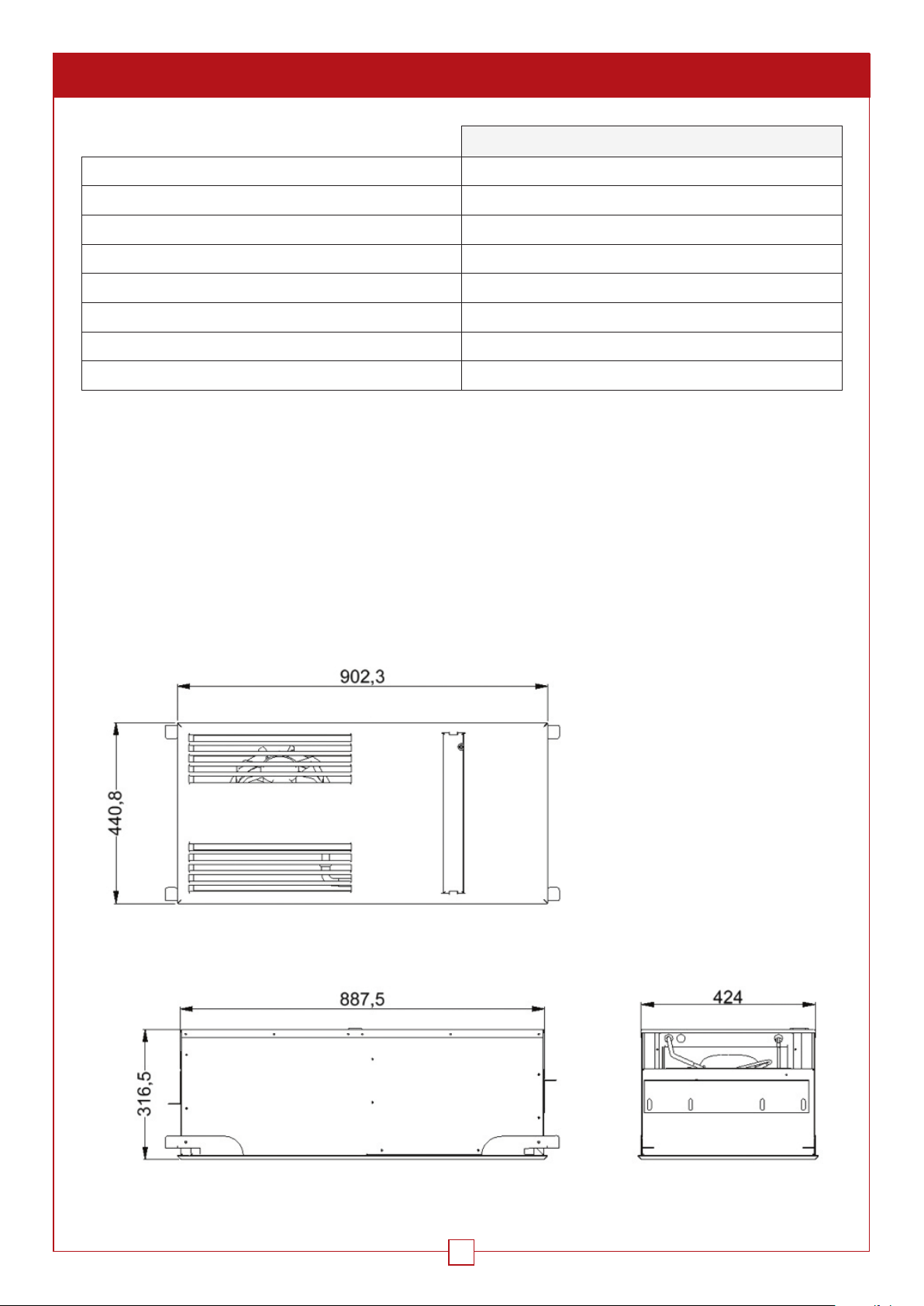
CHARACTERISTICS
WINEARM15
Weight of appliance 31 kg
Dimensions of appliance L908xD439xH316
Cut-out dimensions 890 x 428
Temperature setting preset to 12°C, adjustable between 4 and 15°C *
Max. outside temperature 35°C **
Cooling power 500 W at 15°C **
Electrical power supply 235V-50 Hz + 3 metre cable
Absorbed electrical power 400 W
The circuit breaker must be ≥ 16 Amps
* With insulation appropriate to the temperature and volume of the cellar.
** Since the power diminishes as a function of the outside temperature, the appliance might lose its capacity to
maintain 12°C if the outside temperature nears 35°C.
If the thermal safety function is triggered too frequently, this may damage the compressor prematurely. In all cases,
you should ensure the temperature of the evacuation room is not 35°C on a permanent basis. This high temperature
should furthermore be limited to summer seasons only.
TECHNICAL & DIMENSIONAL DRAWING
WINEARM 15 USER GUIDE
4
Page 5
1. CABINET LAYOUT
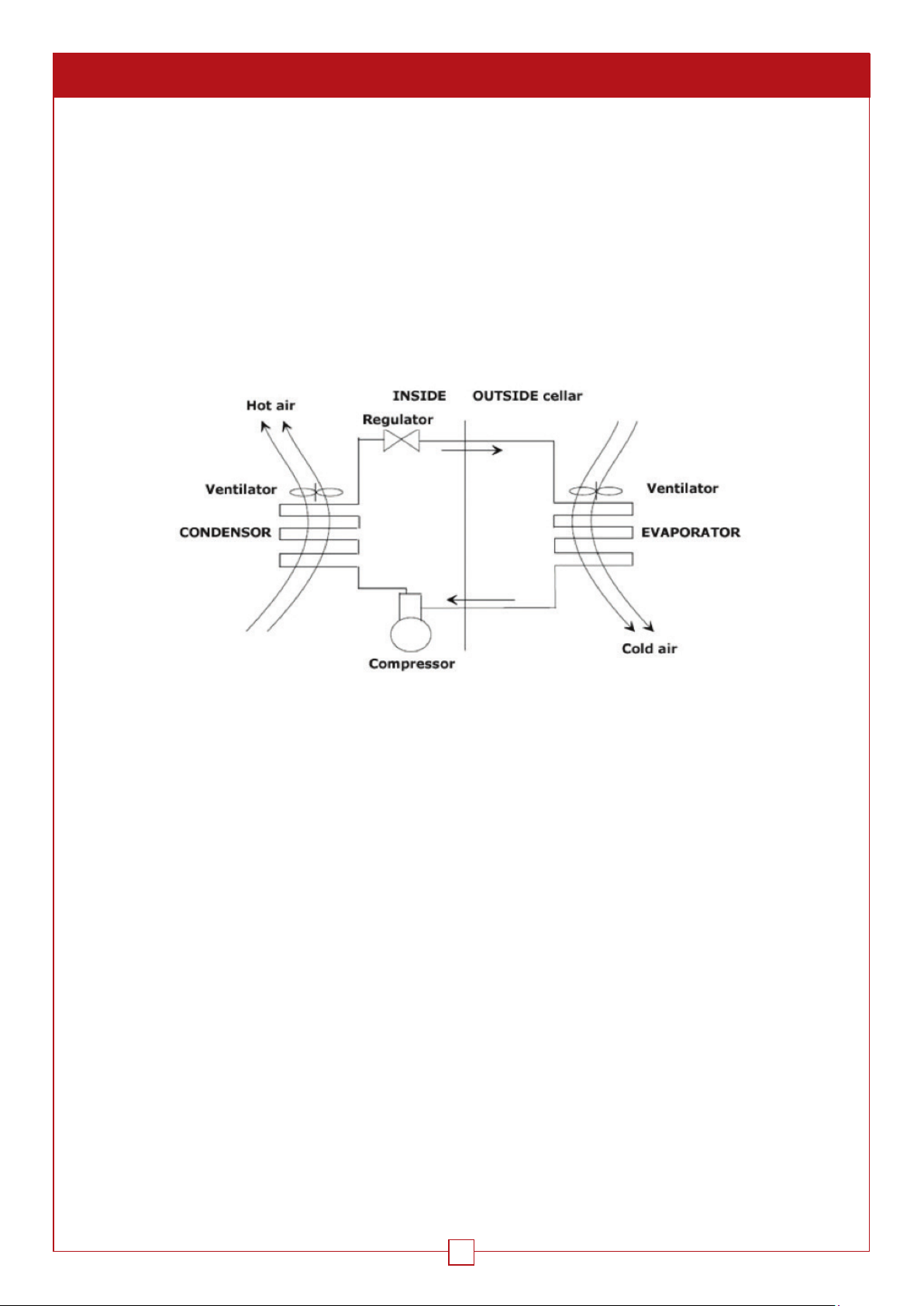
The conditioning unit is installed in the ceiling of the wine cabinet. To work correctly, the appliance evacuates the air
outside at approximately 20°C above the inlet temperature.
1.1. EVACUATION
The hot air produced by the conditioning unit must be correctly evacuated so that it is not reused for the cooling
function.
Maximum and non-permanent inlet temperature ≤ 35°C
Optimal inlet temperature ≈ 20°C
VENTILATED COOLING OR “NO FROST”
The benefits of ventilated cooling:
• No frost formation other than on the evaporator.
• Automatic defrost producing maximum refrigeration efficiency.
• Cold circulation improved by continuous air movement, no air stratification.
• Air circulation allows for rapid return to the preset temperature.
1.2. CABINET INSULATION
This is vital to ensure the efficient operation of the WINEMASTER
temperature and humidity stability. The table below (Choice of insulation) assists with determining the type and
thickness of the necessary insulation as a function of the outside volume of the cellar and the WINEMASTER
and based on an interior temperature of 12°C.
INSULATION CONTINUITY
The insulation elements should preferably be assembled:
• By “tongue and groove” panels, or
• By bonding the panels together
OBJECTIVE: To prevent the unwanted entry of heat and moisture which would damage their tightness.
To prevent moisture migration in the cellar, a vapour barrier should be fitted at the cabinet installation site.
®
. Adequate insulation will help to ensure a better
®
model,
WINEARM 15 USER GUIDE
5
Page 6
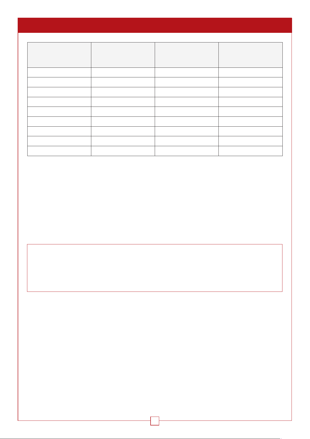
1. CABINET LAYOUT Cont.
Polystyrene foam
Cabinet volume (m³)
= 0.044 W/m°C
(mm)
2 25 20 20
3 30 25 20
4 40 30 25
5 45 30 25
6 50 35 30
8 60 45 40
10 80 55 45
12 90 65 55
15 110 80 70
1.2.1 WALLS, CEILING AND FLOOR INSULATION
Choice of insulation panels
The manufacturers recommend ≠ insulation panels:
• Single insulation panels,
Extruded polystyrene
= 0.030 W/m°C
(mm)
Polyurethane foam
= 0.025 W/m°C
(mm)
• “Complex” insulation: insulation is covered with a cladding material (plaster, mineral, etc.),
• Sandwich: insulation is covered on each side with a wooden panel or plaster board.
Important: the covering protects the insulation from impact and guarantees its longevity. Avoid using mineral-
fibre insulation panels (glass wool, rock wool, etc.) as they can absorb moisture and lose their insulation power.
Furthermore, thin-layer insulation is not as effective for cold applications.
DID YOU KNOW?
Some insulating materials are damaged by rodents (mice, rats, etc.). You should therefore check that the cellar
walls have no orifices through which rodents can reach the insulation. If necessary, cover the insulation on the
inside of the cellar with a protective liner.
Polyurethane as an insulating material, due to its chemical composition, will not be damaged by rodents.
Floor insulation
The cellar floor must be able to support the racks and the wine stored. Insulation must therefore be chosen with a
sufficient compressive resistance.
Puncture resistance (particularly the rack legs) ensured by:
• “Complex” insulation panels, covering their top side with a sufficiently resistant panel.
• Covering the insulation with a chipboard panel (thickness around 15 mm), or any other appropriate covering (e.g.
screed and slab).
1.2.2 DOORS
These form part of the insulation continuity. There are two possible solutions:
• Glazed doors: double-glazing or even triple-glazing must be used with a good UG coefficient (max. 1.2 W/…….)
• If solid doors are used, they should be insulated in the same way as the other walls.
WINEARM 15 USER GUIDE
6
Page 7
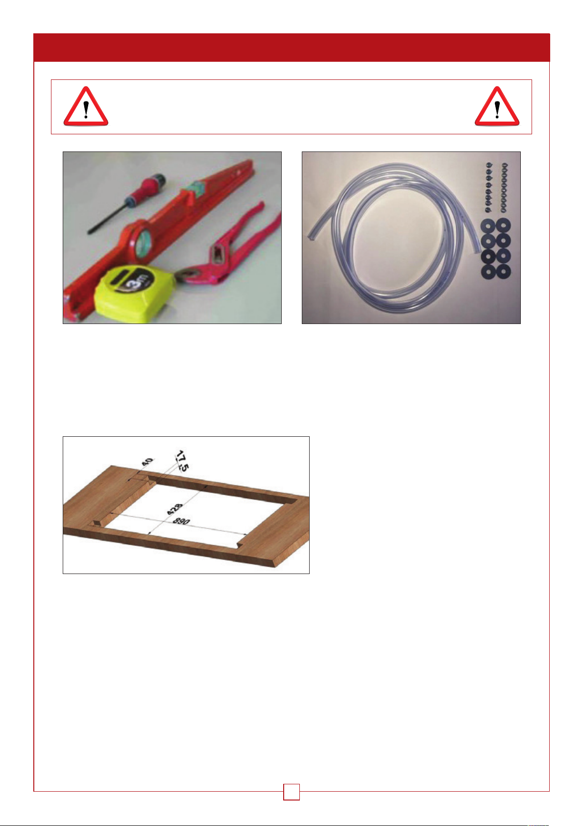
2. INSTALLATION OF THE WINEMASTER® CONDITIONING UNIT
THE APPLIANCE MUST INSTALLED IN COMPLIANCE
WITH NATIONAL ELECTRICAL INSTALLATION RULES
Tools required (not supplied)
2.1 CUTTING THE CEILING
Cut a space in the ceiling to house the conditioning unit.
1.
Cut the ceiling and adjust the slots for the legs if these are used
Items included in box
WINEARM 15 USER GUIDE
7
Page 8
2. INSTALLATION OF THE WINEMASTER® CONDITIONING UNIT Cont.
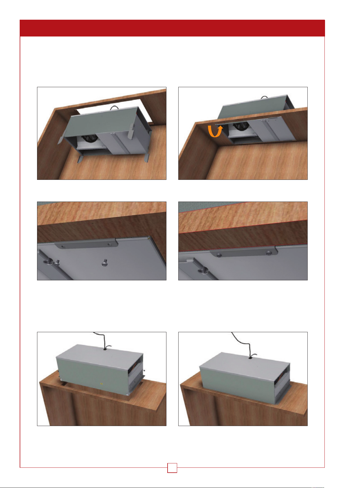
2.2 INSTALLATION OF THE CONDITIONING UNIT
2.2.1 INSERTION OF THE APPLIANCE FROM THE INSIDE OF THE CABINET
The conditioning unit can be positioned in the ceiling from the inside of the cabinet and fastened in place with
the 4 swivel legs integral with the conditioning unit
2.
Engage the conditioning unit in the cut-out space
4.
3.
Turn the 4 legs
5.
Screw in place using the 4 x 6 screws supplied
2.2.2 INSERTION OF THE APPLIANCE FROM ABOVE
If installing from above, you can dismantle the 4 swivel legs designed to hold the conditioning unit in place and
use the brackets supplied.
2.
Insert the unit into the cut-out space from above
3.
Fix the brackets with the screws supplied
WINEARM 15 USER GUIDE
8
Page 9
2. INSTALLATION OF THE WINEMASTER® CONDITIONING UNIT Cont.
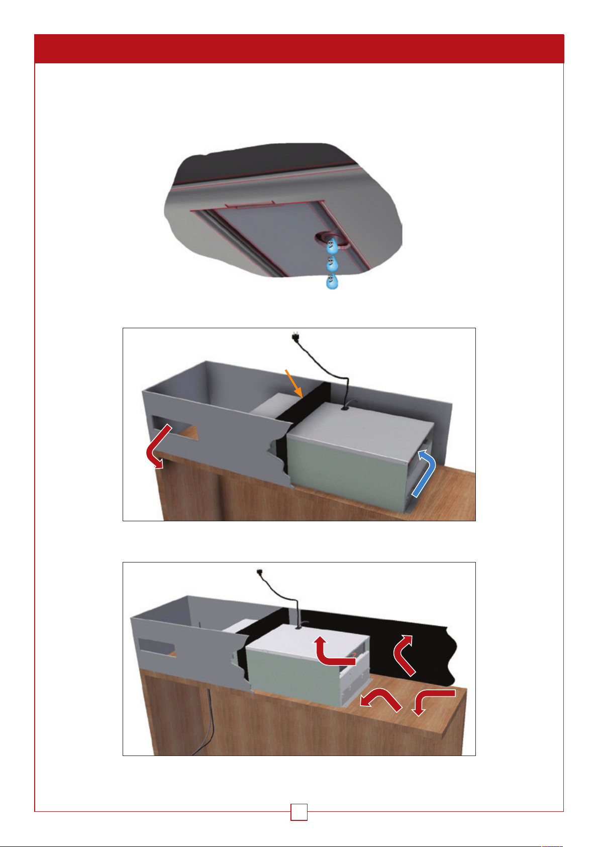
2.2.3 INSTALLATION OF THE WATER DRAIN-OFF
The conditioning unit has a condensate evaporation system. However, there is an overflow to evacuate excess water
caused by the inadequate sealing of the cabinet or the doors remaining open for too long. You can drain off the water
using a PVC pipe channelled to a receptacle.
2.2.4 DUCT VENTILATION
A
Separate the air flows. The free passage area of each grille is 200 cm². Separation A is not
supplied. Ensure the separation is adequately sealed.
WINEARM 15 USER GUIDE
Additional sound insulation can be installed. This is particularly useful for the
suction on all walls.
9
Page 10
2. INSTALLATION OF THE WINEMASTER® CONDITIONING UNIT Cont.
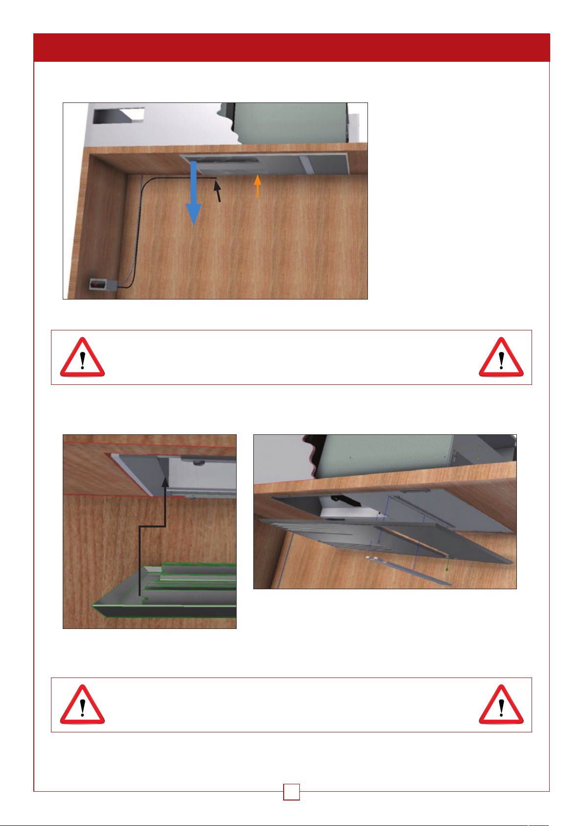
2.2.5 INSTALLATION OF THE THERMOSTAT
The thermostat can be installed
in the cabinet, on the side of the
cabinet or outside the cabinet. Its
sensor (S) should be positioned
towards the return air zone (R). We
recommend that the end of the
sensor does not touch the partition
and is situated in the air flow.
IF THE POWER CABLE IS DAMAGED, IT MUST BE REPLACED BY THE
MANUFACTURER, ITS AFTER-SALES SERVICE OR PERSONS WITH A
SIMILAR QUALIFICATION TO AVOID ANY RISKS.
2.2.6 INSTALLATION OF THE HOOD
S
R
WINEARM 15 USER GUIDE
The hood is inserted on the left at the point of the slots and
then screwed in. The cover is magnetic.
IMPORTANT: AFTER TRANSPORT OR HANDLING, WAIT 24 HOURS
BEFORE CONNECTING THE CONDITIONING UNIT.
10
Page 11
3. SWITCHING ON THE WINEMASTER® CONDITIONING UNIT
IMPORTANT: AFTER TRANSPORT OR HANDLING, WAIT 24 HOURS
BEFORE CONNECTING THE CONDITIONING UNIT.
The thermostat displays the air temperature inside the air-conditioned room, within a range of 2°C. The thermostat
is factory-set to the setpoint temperature of 12°C. When the conditioning unit is switched on, you should check and
modify this temperature if necessary, following the relevant procedure (§4.2.1).
3.1. CONNECTING THE CONDITIONING UNIT
When you switch on the conditioning unit, the temperature of the room is displayed:
- If the temperature is higher than the thermostat setpoint: the conditioning unit will start after a 2-minute time
interval.
- If the temperature is less than the thermostat setpoint: the compressor will not start, the interior unit fan will
simply begin to turn.
3.2. SWITCHING ON
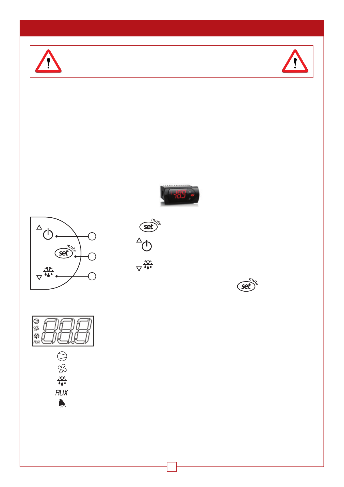
3.2.1. Setting the temperature
The setpoint temperature is set on the thermostat:
• Press the button for one second until the setpoint temperature flashes.
1
• Use the button to increase the setpoint temperature.
2
• Use the button to reduce the setpoint temperature.
3
• When the temperature setting is correct, press the button to confirm
Meanings of the main symbols on the digital display:
Red light illuminated on display = cold mode engaged (compressor)
Red light illuminated on display = quick ventilation in cold mode
Red light illuminated and displayed “dF” = automatic defrost in progress
Red light illuminated on display = heat mode engaged (resistance)
Red light illuminated on display = alarm (a flashing message specifies the nature)
“IA” display = external alarm or door open (depending on version)
“dEF” display = Manual defrost in progress (see 1.2.4)
WINEARM 15 USER GUIDE
11
Page 12
3. SWITCHING ON THE WINEMASTER® CONDITIONING UNIT Cont.
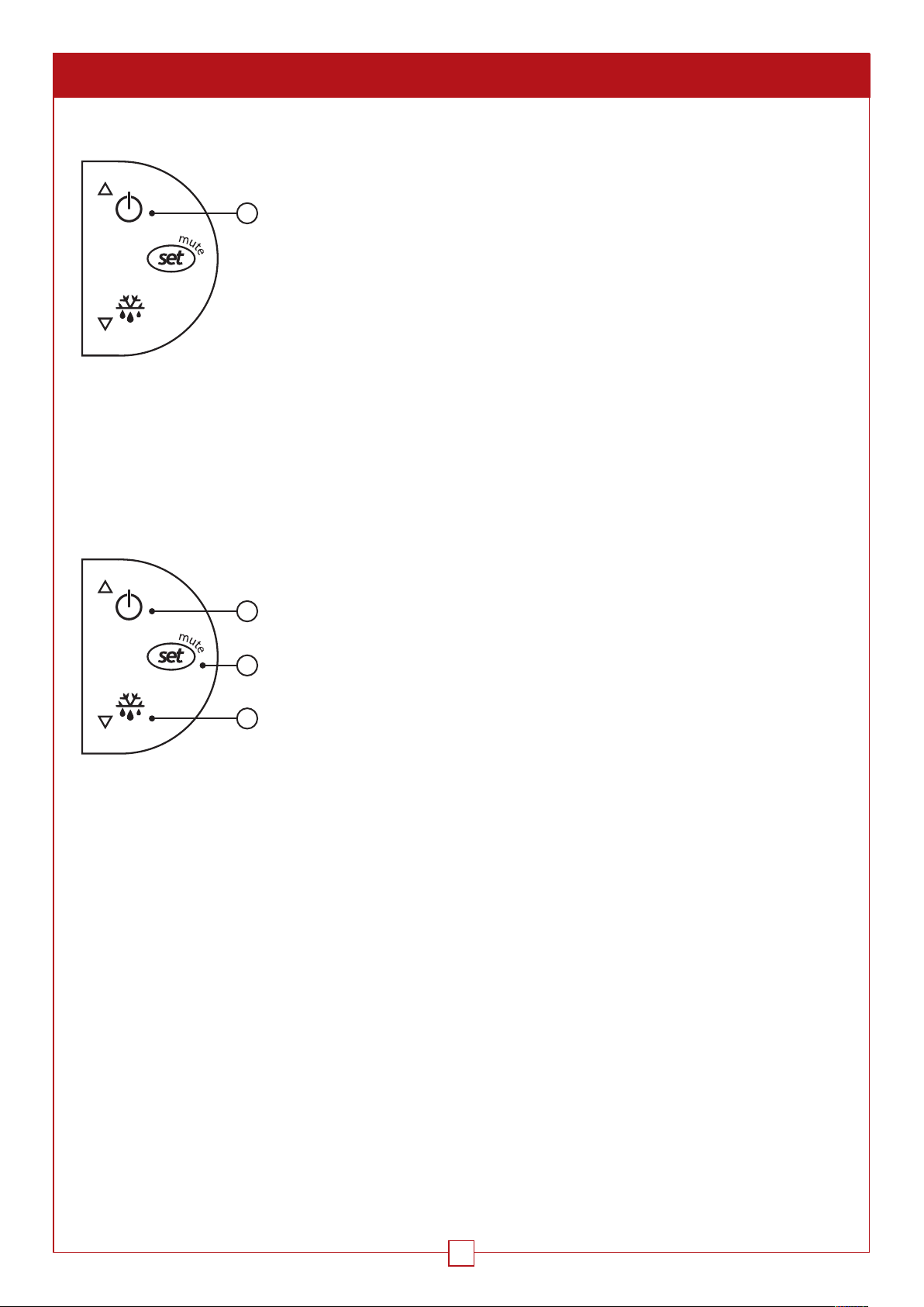
3.2.2. Standby Mode
• Placing the conditioning unit in standby mode: keep button 1 pressed for 3
seconds. The compressor stops and the fan turns at low speed.
1
• The thermostat display alternates between “OFF” and the cellar temperature.
• To exit standby mode, press button 1 again for 3 seconds.
• The thermostat displays “ON” for 1 second.
3.2.3. Automatic Defrost
The thermostat is programmed to run an automatic defrost at regular intervals. This involves the shutdown of the
compressor, while the interior unit fan will continue to turn at low-speed. Any condensates produced by the defrost
will be evacuated to the evaporation pan placed underneath the compressor inside the Winemaster
overflow is evacuated by the orifice situated next to the dust filter access hatch.
®
. If necessary, the
3.2.4. Manual Defrost
1
• Manual defrost is not necessary, but can however be activated by pressing button
3 for 3 seconds. The compressor shuts down.
• The thermostat display alternates between “dEF” and the cellar temperature.
2
• To exit manual defrost mode, press button 3 again for 3 seconds.
• The thermostat displays “ON” for 1 second.
3
WINEARM 15 USER GUIDE
12
Page 13
4. SERVICING & MAINTAINING
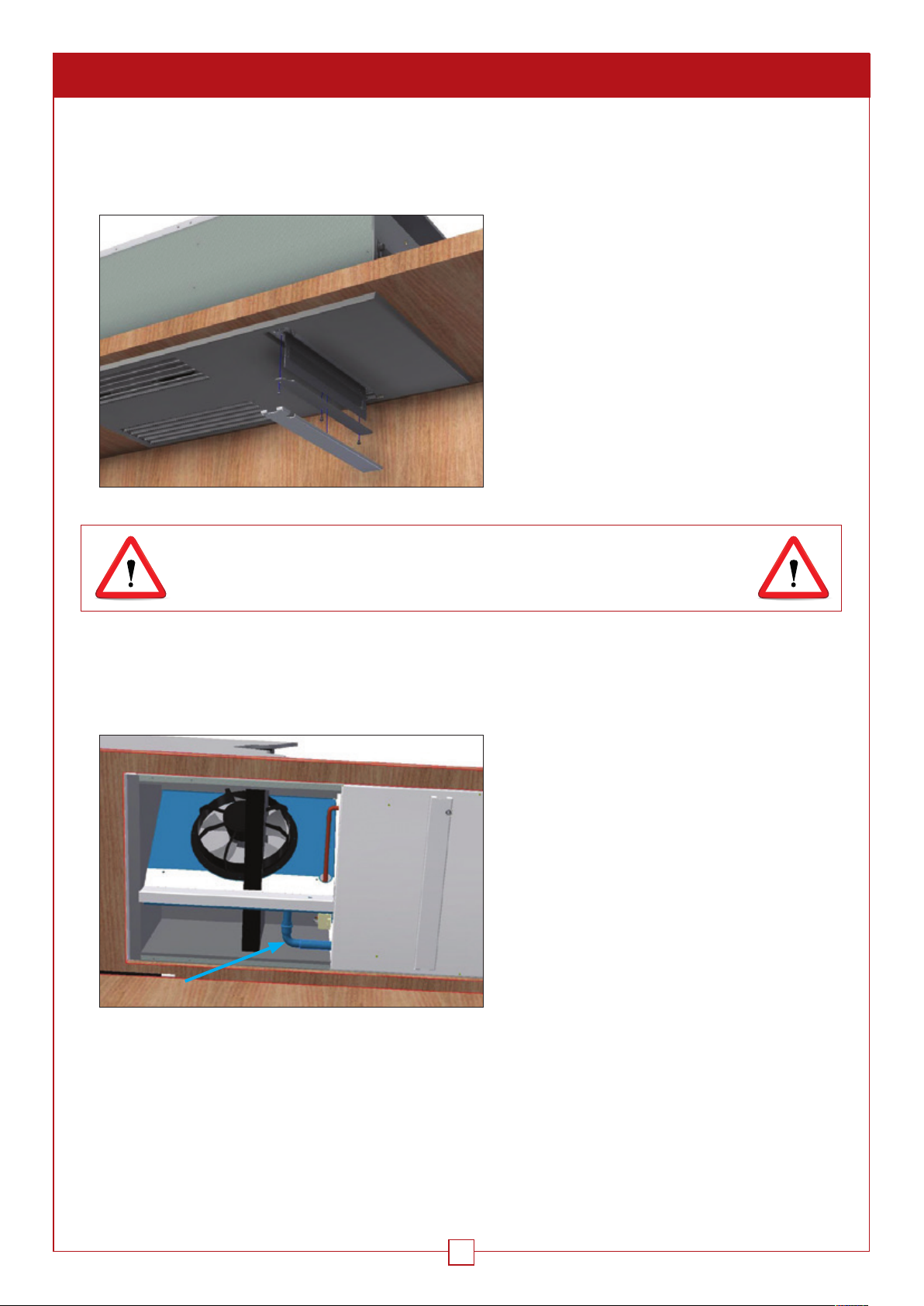
4.1. MAINTAINING THE DUST FILTER
The unit is equipped with a dust filter, which protects the conditioning unit from clogging. The dust filter should be
checked regularly and replaced at least once a year. The filter is accessed from the bottom of the conditioning unit.
• Remove the magnetic cover
• Remove the 2 screws securing the shutter
• Remove the filter
• Replace with the new filter
CLOGGED FILTER = DAMAGED CONDITIONING UNIT
MAKE SURE YOU USE WINEMASTER
4.2. CONDENSATE EVACUATION PIPE
Check this is not obstructed and clean it at least once a year.
®
FILTERS ONLY
• Remove outer hood (see § 2.2.6)
• The stainless steel elbow can be removed
• Remove the deposits in the pipe
• Reassemble the elbow and then replace the hood
WINEARM 15 USER GUIDE
13
Page 14
5. WARRANTY
5.1. STATUTORY WARRANTY
The statutory warranty for hidden faults and defects applies pursuant to the conditions of articles 1641 et seq. of the
French Civil Code. The statutory warranty for compliance is applied in accordance with the conditions of article L2111 et seq. of the French Consumer Code.
5.2. 2-YEAR CONTRACTUAL WARRANTY
The conditioning unit has a 2-year warranty against all manufacturing defects.
During the contractual warranty period, FONDIS will replace any part recognised as faulty. Depending on the case,
the FONDIS after-sales service may request the return of the faulty part. The part replacements or their repair will not
serve to extend the warranty period.
Payment of the transport costs falls to the user.
Interventions and returns should take place only after the written agreement of the FONDIS after-sales service.
5.3. WARRANTY APPLICATION CONDITIONS
The contractual warranty applies to all appliances installed and used in accordance with the “Installation and User
Guide”. Its application is dependent upon the presentation of the purchase invoice or, otherwise, a copy of the latter.
5.4. WARRANTY EXCLUSIONS AND LIMITATIONS
The warranty is excluded in the following cases:
• The insulation of the climate-controlled room and the installation fail to comply with the instructions of this Guide.
• The faults are due to negligence, poor repair, incorrect or improper use of the WINEMASTER® conditioning unit
(particularly the clogging of the filters).
• The appliance has been modified
FONDIS will under no circumstance be liable for the direct or indirect consequences of the non-operation of the
conditioning unit. The warranty is limited exclusively to the product supplied by FONDIS.
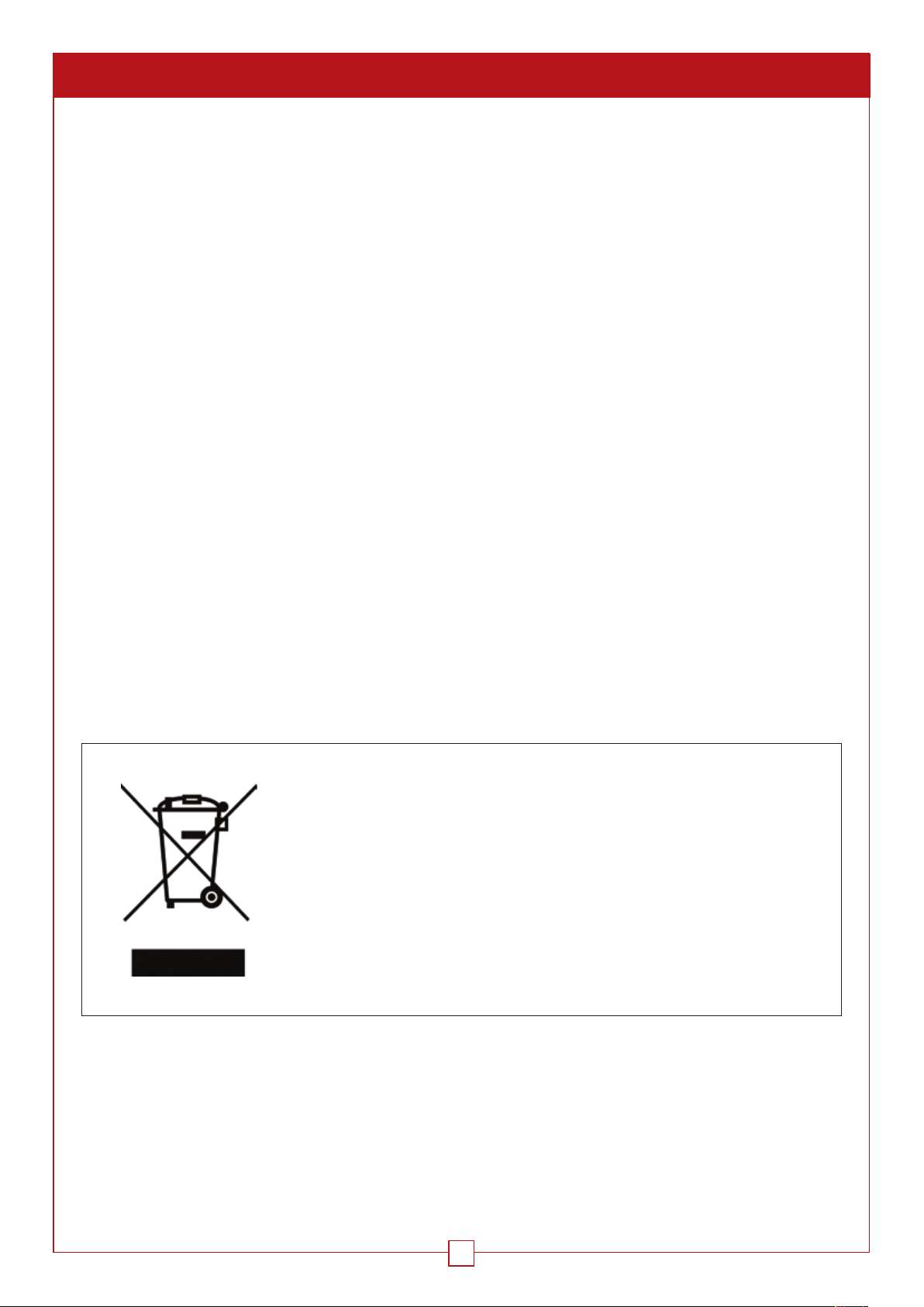
The European Community, placing great importance on the environment and the
treatment of waste, implemented Directive 2002/96/EC relating to Electrical and
Electronic Waste (WEEE).
In accordance with this Directive, the presence of the logo on the left is
compulsory.
This logo means that the product must never be disposed of in household waste.
It must be taken to a suitable collection point for the processing, recovery and
recycling of electrical and electronic waste.
By doing so, you are acting for the environment and contributing to the
protection of natural resources and human health.
WINEARM 15 USER GUIDE
14
Page 15

WINEARM 15 USER GUIDE
15
Page 16

Wine Corner Limited, Unit 4 Brunel Close,
Harworth, Doncaster, South Yorkshire, DN11 8QA
Tel: 00 44 (0) 1302 744916
or 03333 702589
E-mail: [email protected]
WineCornerUK
@winecorner1
linkedin.com/company/wine-corner-ltd
© Wine Corner Limited 2017. We reserve the right to change product specifications and
prices without prior notice. Wine Corner Limited does not accept any responsibility for any
loss, which may arise as a consequence of reliance on information contained in this brochure.
DEFYING
CONVENTION
 Loading...