

Windsor Trident Compact TC17BJ, Trident Compact TC17PK, Trident Compact TC20BJ, Trident Compact TC20X, Trident Compact TC20PK Operator's Manual
...Page 1
TRIDENT COMPACT 17"
24VDC (S/N
5000001 & BELOW) - 98096
I
QMST
.
.
.for
Continuous
Improwmant.
Windsor's
Puolity
Monopwmt
System
is
CduJ
IS0
9001.
Battery Powered
Floor Scrubber
with Removable
MODELS
TC17,
TC20,
TC17BJ, TCmBJ,
Battery System
TC2OX,
TC17PK, TC20PK
dm
WINDSOR
I
N
DUSTR
I
ES
,
INC.,
iasi
W
.
S~MM
AVO,
engkwood
co
miio
wc~~xa-iw~mx
sos-~i7
inims
b
Page 2
2
TRIDENT COMPACT
17
"
24VDC (S/N
5000001 & BELOW)
Operator Safety Instructions
WARNING:
Read the instruction
manual before operating machine.
Operate
thls
machine only from the rear
of
machine.
CAUTION: For
Indoor Use Only.
To
prevent possible damage to the floor whe using the
Brush use water or other approved cleaning solution
while operating.
When using the pad option, always keep the machine
moving when
in
contact with
the
floor.
Use caution when operating the machine on a ramp
or incline.
Do
not
turn
or leave
thls
machine unattended
on a ramp or incline.
Make sure all Warning and Caution labels are legible
and properly attached
to
the machine.
Store machine Inside. Keep
the
electrical components
of
the machine dry.
Lead acid batteries generate gasses which can cause
an explosion. Keep sparks and flames away from the
batteries, Charge
the
batteries only
in
a
well ventl-
lated
area.
Wear
eye protection when working near batteries.
Do
not
put
any
type
of
metal objects across the battery
terminals or on top of the batteries.
Maintenance and repairs
must
be
done by qualified
personnel only. Maintain adjustments on machlne
as per specifications noted
In
the service manual.
Machine
can
cause an explosion when operated near
flammable vapors and materials.
Page 3
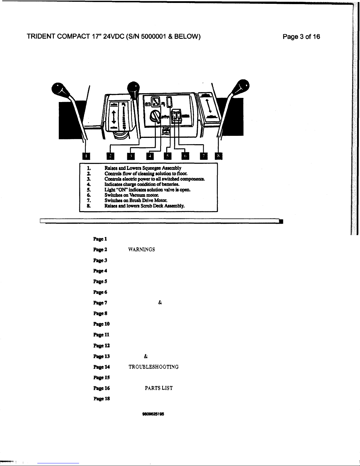
CONTROLS
CONTENTS
INTRODUCTION
WARNINGS
CONTROLS
MACHINE PREPERATION
OPERATING MACHINE
-
CHARGING
SERVICING
TANKS, VAC
k
FRAME
SCRUB
DECK
ELECTRICAL CONTROLS
MECHANICAL CONTROLS
SQUEEGEE
PUMP 6 STANDARD MODEL
TROUBLESH00"ING
WIRING DIAGRAM
SPARE
PARTS
UST
WARRANTY
3
Page 4
TRIDENT COMPACT 17" 24VDC (S/N
5000001
&
BELOW)
MACHINE PREPARATION
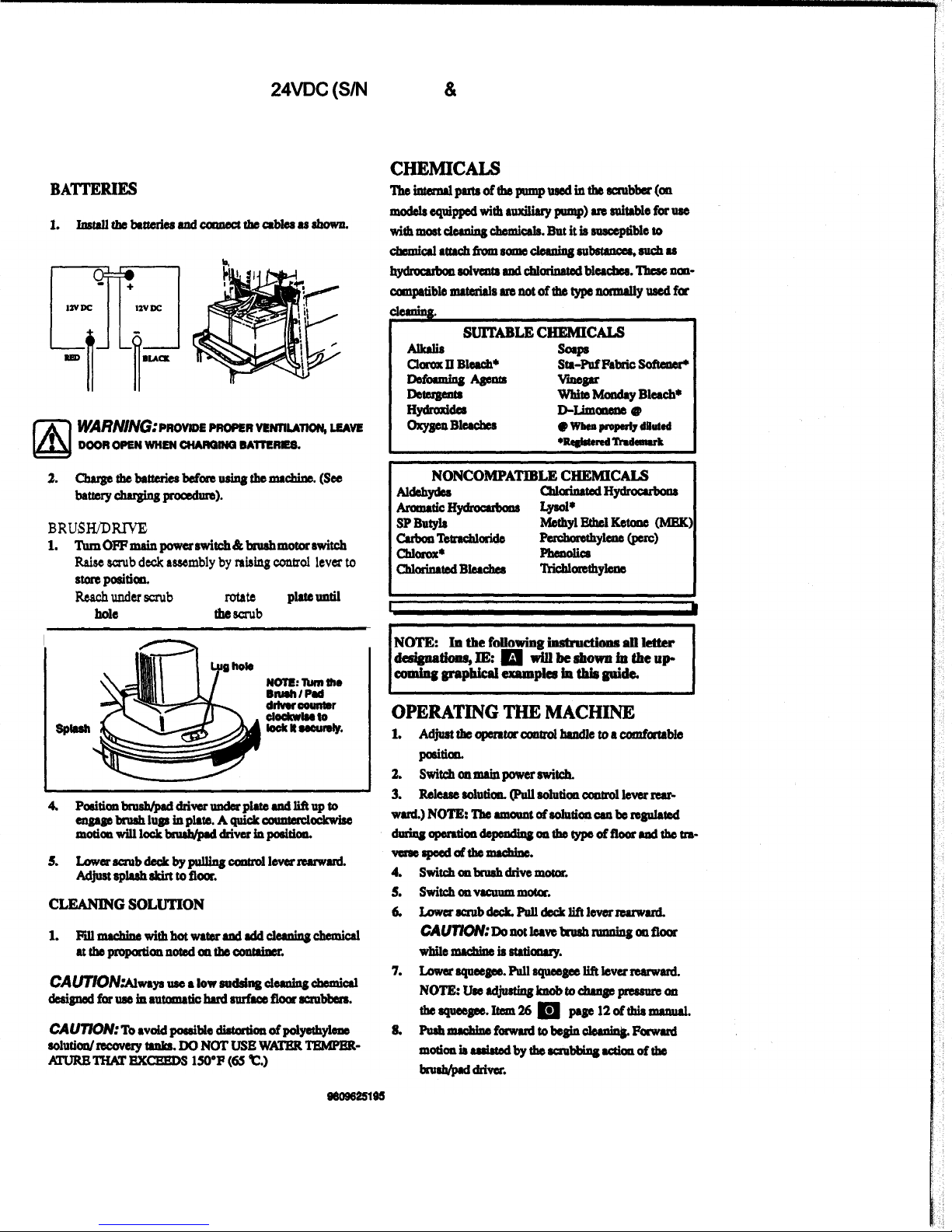
BA'ITERIES
BRUSWDRWE
PAD ASSEMBLY
2.
Raisewubdcclcaswmblybynhingoantral
leverto
3.
1.
TUm
omdv
dtch
&
bN&
mOtar
Ewitch
EtOaPdti~
Reachunder
shlb
deck
and
rotato
drive
plate
until
a
lug
hole
is
visible
through
the
wub
deck
sight
hole.
I
1
Sp-
4
9809825195
Page 5
TRIDENT COMPACT
17
"
24VDC
(S/N
5000001
&
BELOW)
OPERATING
MACHINE WITH
ACCESSORY
TOOLS
The
m
floa
tool
for
wet
pick-up
can
be
wed
011
mo&la
equipped
with
the
arurilLuy
pump
kit
option.
(NOTE:
Fao-
tayinstallcd
option
ally.)
1.
Remove
vac
hose
&om
aqucegca
and
camcctto
rcctaaoly
v.c
hose,
nsiq
metrl
hoac
caupler.
2.
~aolutionboscfranIcas~toolto
solution
outlet
nipple
located
at
lawer
right
hand
~ofrwprmet.
make
aule
dome
is
in
place.
3.
checlrsolutiontrnlcfordeaniugaolu~oarad
4.
switchmrminpawer$wi~
5.
Switchmauxiliuypumpradvacuumswitchea.
WNW":
Do
not
mriteh
on
bN8h
motor
when
opemtlng
mchine
with
t
€&I
acceuory
took.
REGULARMAINTENANCE
BEFORE STARTING
WORK
PERIOD
1.
Discoamcct
battuy
chtnget.
NOTE:
Dhamect
the
mllovitlg
the
"Dc'
Qlger
plug
fram
the
macbim.
"AC"
power
cord
fiom
ths
wall
xeceptacle
befm
2.
Check
water
level
in
battaies.
Add
&tilled
water
a$
needed.
3.
AItrchbmhordrivepadtodrivaplrte.
4.
CheckVrr:hOse~
'on
at
aqucegw
ahoc.
5.
Qleck
squeepc
blades
for
war.
6.
mumacbincwithhotwatermdidddcllningcbamicrl
at
the
proportiomnoted
OII
the
contabr.
NOTE:
Use
a
low
audaing
clernsr
dd@
for
we
in
automatic
hardsurfaccflooraaubbaa.
BEFORESTORWGMACHINEAT
THE
END
OF
WORK PERIOD:
1.
2.
Dninboth
mlutimand
mcoMly
tanks
radrinsccl~.
Aftarerch
use,
rinw
tmlwithfruh
Wlter.
paiodicrlly
inrpsct
thCrccOvSytdUUidCCOa~~if~,,l
wum
wta
rhould
be
dirporod
ofpropdy.
Removs
dams.
lift
at
nwt
Maembly
to
allow
~ClytUlktorirdIy.
upside aownahrng
on
wall.
Horpitrl
onds
Viludd8
Q
11-10
bkreh
toe
rolutioll.
3.
4.
hUOW
bnuh
OrdrlVC
p&
from
ddVC
md
5.
Wipcdown8xtsriaofmachincwithdampcloth.
6.
Raiaesquesgscasssmbryto'ktae"positioe
7.
BATTERIES - CHARGING
AND
MAINTENANCE
BATIERY CHARGING PROCEDURE
WARN/NG.Lemd
add
bplteriw
generate
guseb
which
can
cause
an
explosion.
m
Keep
sp.rk
and
flames
away
from
Mterles.
NO
SMOKING.
Alwaya
wear
eye
nwbatterisr.
Qroe
the
bnttdal
only
in
a
well
vcntilrtsd
(hrgc
battdcd.
(Sec
Battery
chruglno
proadms)
when working
area.
BATTERIES - CHARGING
AND
BATTERY CHARGING PROCEDURE
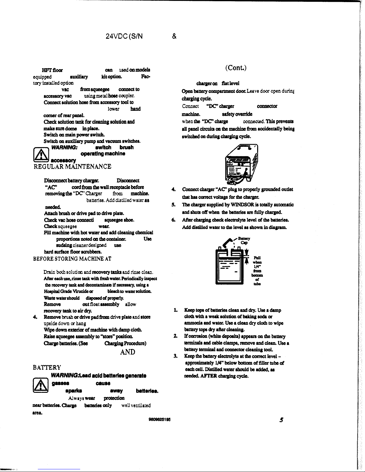
1.
2.
opsnba~comp~tdggp.
Lervedoaropcn~
MAINTENANCE (Conk)
Set
the
dqpr
011
a
flat
level
dace.
chargingcycle.
coanact
the
"Wchuger
plug
to
the
camctor
on
the
machine.
NOTE:
A
safety
ovaride
switch
is
activated
whml
th
"Dc.chrge
plug
is
comnscted.
Tbisprevcnta
allplnelcircpitsonthcrmchino
fmmrcCi&dybdqs
swiw
011duriIlgcht.gingcycla.
3.
BATTERY MAINTENANCE
5
Page 6

TRIDENT COMPACT 17" 24VDC (S/N
5000001
81
BELOW)
SERVICING
THE
POWERTEC
SCRUBBER
CAU77ON;
Before making
and adjustments
or
repairs
to
the
machi
ne...
1.
Onlyqulifieedrnrintsnuvxpsrsool3alrrato
w-reprita.
2.
Makembattarychuga3;1discormeotad
Make
sum
111
switchw
am
"
OFF'.
d
RCmOWboUMarepuireda-
main
battWyldS~barraitfJwhen~nprirs
toelcarical~tcm..
5.
Raferto~dia~whenreplrcinselectricll
e1ectricalpartsarepilingelactricrlsyStam.
3.
SQUEEGEE ASSEMBLY
lb
remove
squeegee
assembly.
..
ADJUSTMENT
OF
SQUEEGEE
VACUUM
MOTOR
1.
Di~tbiatteryI~andrCm~h~ea
fromcoanpsI.rmcnt.
2. Remove
(6)
acmws
holding
motor/
plate
3.
DiscoPlnsct
vacmotorlud
lpfromcamctar
4.
==lblY~rscoverYtmL.
a
and
lift
out
VIC
motor/
plate
rsscmbly.
Check
motor
brushes.
When
WOPIL
to
3/8"
npb
bothbnlshe4J.
Lp
-
_.
..
PUMP
ASSEMBLY
(On
mod&
equipped with
auxiliary
pump)
1.
2.
Removb
batteries
and
qmgce
u#mbly.
Lay
the
mrchinsanside.
Discamsctpump
motaluds.
Remove
(4)
acmws
holdingpllmptochrssis.~
EOlUtiOIl
boscsfmmDpumphsrd~
udliffautpump
dnwiogfornpl~~
Oa
SOLUTION
STRAINER
1.
Aninlinasolutianstninarhlocateduadcr~
behind
left
WW.
Remow
sadimsntbowl
ruad
(LQasn
paiodicdly
Md
rinse
clean
withhot
water.
Be
anful
not
to
misplrcs
the
Oaskct.
SCRUB DECK / BRUSH
MOTOR
Page 7

TRIDENT COMPACT
17”
24VDC (S/N 5000001
&
BELOW)
8
48-
47
I
-
.
-
..
KEY
1
2
3
4
5
6
7
8
9
10
11
12
13
14
15
16
17
18
19
20
21
22
23
24
2s
26
27
28
29
30
31
32
33
34
35
PART
#
70251
75152
50363
51138
27416
87090
571
05
75153
70393
50485
28049
57026
87147
62433
3S141
14844
73704
35088
571
04
70088
28048
35060
70114
78294
34258
36150
20046
271
88
68061
4001
9
20002
39037
27282
3-
27079
DESCRIPTION
Sol
Scrow,
114-20 x 3.5
HHMS
lank,
Solution
Label,
soMionwamiq
Lid,
Solution
tank
cord,
Sdutkn
IM
Washer,
114
Irt
Nut,
1/4-90
hox wlwu
Tank,
Recovrry
Set
Screw,
1/4-20 x 1.25L
Label.
WINDSOR
logo
Float
Asm,
Vac
shut-ol1
NU.
8/32
Ny-kok
Washer,
#12
sod
Plate,
Float
Qasket,Rnk
Screen,
Fbat
Q~ket,
Float
shut-Oll
Nut,
10-32wlatarwa8her
su.
10-32 x 3/4
Dome,
Mod.
Pt17
Gasket,
Dome
SU,
#lo x w4
pdyfast
Tube,
V.c
motor
Filter,
virc
Intala
Oukot,
Vac
motor
Clamp, 2.25
how
Cord,
Drain
tmm
plw
Plug,
Dnin
hoes
Horrbarb,
1.5 do&e
Clamp,
r
Nylon
Hore,
1
.5 x 24’
drain
CM, 1.5
dlp
x
1.5
ho6e
HO6Okm.W
CM,l.SwMIlom
w
KEY
31
37
38
39A
39B
40
41
42
43
44
45
46
47
48
49A
498
so
51
52
53
54
56
56
57
5a
58
60
61
62
63
64
85
60
67
I
jo
-
60
Note
#67
goe8
tbru
Us
PART#
70085
87025
35122
53756
53198
62279
78004
76015
73491
62350
20605
87016
14696
701 14
50518
-19
34108
70010
61286
70020
23174
57116
70327
27268
om10
89068
73437
27408
70119
03058
57119
70266
88894
amia
DEBGRIPTION
Sw,
1/4-20 x 1/2
PHMS
Washer,
114
star
Gasket
vao
fan
soal
v.C
Mtr,
wl
COM.
24VDC 5.7
v.C
Mtr.,
24V 5.7 3
8tg.
Acwtrk
Plate,
vpc
dMdrr
Comctor,
2-pin
M-mdex
Temhl,
Female
pin
molex
Spwr,
Vac
motor
Plate,
he
OaVIc
aunR
5/16
nvkn
Wuk,
#lo
rtu
BtuBhmt,vacmotor
Sa,
110 x 9/4
Polyfrwt
W,
TC17
Wl,lGacomm~
Fnmr,
Main
Panel,
Rear
&r,
1/4-20 x 112
HHMS
We
mm,
TC
ban.
~c171po4~ca~x
Nut
W32
wMu
wash
TCI~IPO*TCBDX
Sa,
1/4-2oX3/8THMs
mCIClrdwp-k
whoel,
(WMl
ltelllll)
Spacer.
Wheel
axlo
Collar.
Me
8.1
Set,
1/4-20
x
3l6
KCP
Arb,
whd
N~t,3&16kck
Screw,
3/18-16 x 1
HHCS
Win
hm.
TC17
vao
motor
8cr,
114-20 x 1 .5
HHCS
?&?xi
8008825185
7
Page 8

TRIDENT
COMPACT
17”
24VDC (S/N
5000001
&
BELOW)
SCRUB
DECK
8
9808825195
Page 9

TRIDENT COMPACT
17
"
24VDC (S/N
5000001
&
BELOW)
REAR
COMPARTMENT
1
i
Page 10

TRIDENT COMPACT
17”
24VDC
(S/N
5000001
&
BELOW)
ELECTRICAL
CONTROLS
Page 11

TRIDENT COMPACT
17”
24VDC (S/N
5000001
&
BELOW)
MECHANICAL
CONTROLS
Page 12

TRIDENT COMPACT
17
"
24VDC
(S/N
5000001
81
BELOW)
SQUEEGEE
81
SQUEEGEE
LIFT MECHANISM
9809825196
22
Page 13

TRIDENT COMPACT 17"
24VDC
(S/N
5000001 & BELOW)
OARTS
LIST:
KEY
1
2
3
4
5
6
7
8
9
10
11
12
13
14
15
18
17
18
19
20
21
22
23
24
25
26
27
-3a
)b
J
30
31
32
PART
NO.
27507
8701 8
57104
70409
20042
40013
40022
39380
7821 2
ir3983
41
184
59021
73405
27372
70066
14454
70081
38136
84112
14617
40027
99981
5601 2
8701
5
4001 4
9881 1
40034
65104
65105
56038
40040
99297
20(305
DESCRIPTION
Cable,
Solutlon
Washer,
#lo
9116
OD
Nut, 10-32 w/SW
Wher
Scr,
+lox
1R
PH HI-Lo
Clamp,
9/8
Hose
HoMbub,
9/8
MPT
X
1R
Hembarb,
1/2 MPTx
1R
Hose,
1R
x
5"
Cleor
Toe,
9/8
FPT
stralnerm,
solutlon
Houslng,
Strainer
O-RlW,
FIIW
Sd
Scmn,80M.sh
Cap,
Strainer
SU,
10-32
x
514
PHMS
me
valve
W,
10-24 X 1R
FHMS
Handh,
Vdva
LWW
Vdva,WFPT
Brkt
SduHon
Valve
Mtg.
Hosebarb,
W0
MPTx 1R
QOdeg
Hose,
1R
ID
Cleu
x
22'
Nlpple.
114
FPTQD
Waohor,
9116
IDx 1.06
Flat
Hosebarb,
114
MPT
x
W8
HOW,
14
"
Rubb@f
Hosebarb,
3B
MPTx
9/8
9wsg
Pump
Asm,
WKOM.
24V
sopd
Pump
Asm,
wlo
Corn.
24V
SOpd
Nlpple,
We
Close
Hoeebarb,
9/8
FPT
x 1R
Hose
How,
16.
Clw
cllvnp,
5/16"
dk
pkstlc
MODE!
STANDARD MODEL
I
I.
98080111~
13
Page 14

TRIDENT COMPACT
17
"
24VDC (S/N
5000001
&
BELOW)
TROUBLE4HOOTZNG GUZDE
PROBLEM PROBABLE
CAUSE
No
Power
Battery
cabla
cormded
at
b#ery
terminrlr.
Faulty
mein
switch.
Faulty
hty
owride
switch
Vacuum
motor
Circuit
Bxeaker
@ipped.
does
not
run.
Locwccanmactl
'oa
Faulty
vlc
Switch.
Faulty
Vac
My
Faulty
Vac
Cidt
BlUllk&
Motorbnrsheswan
Faulty
Bmh
Switch.
Faulty
Br~h
Reby.
Faulty
Brush
Circuit.
Be
Matortm18heswarn.
Solution
Light
Loose
carraectioas
does
not
mrk.
Faulty
solnti00LigtIt
CORRECTIVE ACTION
Reset
vac
motor
circuit
kslksr
(25
amp).
checlrmotaludcollnectionsatterminrls.
RemawlSrdsrad~switchfa~ty.Reph
aSn#dd
Withrminmitchu0N"mdvrcswit&*'0N"checLvoltrylertpoiats
B
&
I.
Voltage
ahouIdbe22RdVDC.
WNI
main
switch
"ON"
and
vllc
switch
"ON"
check
voltage
at
pointa
B
&
J.
Wtage
rhonldbe
22/26
VDC.
checkmotakuahss.Rephw~womto3/8".wlthbatterits
filly
charged
and
motor
smu8d,
apply
battssy
voltage
dirrcrly
to
motot.
The
amp
draw
of
motor
&odd
be
between
18-24
amp.
Qeckfaloase~
'QU
at
solution
lisbt.
solution
switch
and
at
vac
faarelay
grrmnd.
Rtmove
rishr
d
apply
dirad
voltage
CMVDC)
to
light.
~eplrce
light
as
ncadad
Adjust
solution
light
switch.
14
Page 15

I
I
I
TRIDENT COMPACT
17”
24VDC (S/N
5000001
&
BELOW)
WIRING DIAGRAM
a;!%
i
r@
mm
im
I
I
I
i
I-
I
iw
I
I
I
I
I1
I
II
I
PUMP
PUMP
ASSEMBLY
115V
65019
PUNlP
MOTOR
53188
8809825195
15
 Loading...