

Page 1

FLOOR SWEEPER
MODEL: TRACER FS
QTFSD (Diesel Version)
QTFSG (Gas Version)
Operating Instructions
Read these instructions before using the machine
M
98349 11/01/03
Page 2

MACHINE DATA LOG
2
Address: _______________________________________________________________________________________________
MODEL _______________________________________
DATE OF PURCHASE __________________________
SERIAL NUMBER ______________________________
SALES REPRESENTATIVE # _____________________
DEALER NAME ________________________________
OPERATIONS GUIDE NUMBER ___________________
PUBLISHED __________________________________________
Copyright 1995 Windsor Industries, Printed in USA
YOUR DEALER
Name: __________________________________________________________________________________________________
Phone Number: _________________________________________________________________________________________
OVERVIEW
The Tracer Floor Sweeper is a gas or diesel powered, ride-on floor sweeper intended for industrial
use. The appliance sweeps the floor while vacuuming the dirt into a holding tank.
QTFSG/QTFSD 98349 05/15/03
Page 3

TABLE OF CONTENTS
3
Machine Data Log..........................................2
Table of Contents...........................................3
HOW TO USE THIS MANUAL
How to use this Manual..................................1-1
SAFETY
Important Safety Instructions.........................2-1
Hazard Intensity Level...................................2-2
Safety Label Location.....................................2-3
OPERATIONS
Technical Specifications................................3-1
Controls..........................................................3-2
Machine Operation.........................................3-7
Pre-Run Machine Inspection......................3-7
Starting Machine.........................................3-7
Sweeping.....................................................3-7
Operating on Grades ..................................3-7
Stopping Machine.......................................3-8
Storing Machine..........................................3-8
Dumping the Hopper...................................3-8
Hopper Safety Arm.....................................3-8
Machine Jacking............................................3-9
Machine Tie-Downs .......................................3-9
MAINTENANCE
Hydraulics......................................................4-1
Directional Control System............................4-2
Throttle Neutral Position.................................4-2
Main Broom. ...................................................4-3
Side Broom ....................................................4-5
Belts...............................................................4-6
Differential Drive.............................................4-9
Skirts. .............................................................4-9
Hopper..........................................................4-11
Brakes/Tires.................................................4-13
Battery Information.......................................4-14
Hydraulic Schematic....................................4-15
Hydraulic Troubleshooting...........................4-15
Propelling Troubleshooting..........................4-16
Machine Troubleshooting.............................4-17
Service Schedule.........................................4-18
GROUP PARTS LIST
Frame Group................................................5-1
Differential Group.........................................5-3
Front Wheel Drive Group.............................5-5
Impeller Group.............................................5-7
Impeller (Wet Sweep Bypass).....................5-9
Rear Clip Group...........................................5-11
Console Group.............................................5-13
Brake Group.................................................5-15
Steering Group.............................................5-17
Rear Suspension Group..............................5-19
Engine Group (GAS)....................................5-21
Engine Group (DIESEL-1)...........................5-23
Engine Group (DIESEL-2)...........................5-25
Drive Group..................................................5-27
Side Broom Group.......................................5-29
Filter Group..................................................5-31
Hydraulic Group...........................................5-33
Hopper Group..............................................5-35
Main Broom Lift Group.................................5-37
Main Broom Group.......................................5-39
Instrument Panel Group (GAS)...................5-41
Instrument Panel Group (DIESEL)..............5-43
Wiring Group (GAS).....................................5-45
Wiring Group (DIESEL)...............................5-47
Horn Wire Asm.............................................5-49
Wiring Schematic (GAS)..............................5-51
Wiring Schematic (DIESEL)........................5-52
Engine Service Parts (GAS)........................5-53
Engine Service Parts (DIESEL)...................5-54
HD Air Cleaner.............................................5-55
Notes............................................................5-57
Warranty ......................................................5-58
QTFSG/QTFSD 98349 05/15/03
Page 4

HOW TO USE THIS MANUAL
This manual contains the following sections:
- HOW TO USE THIS MANUAL
- SAFETY
- OPERATIONS
- MAINTENANCE
- PARTS LIST
The HOW TO USE THIS MANUAL section will tell
you how to find important information for ordering
correct repair parts.
Parts may be ordered from authorized Windsor
dealers. When placing an order for parts, the
machine model and machine serial number are
important. Refer to the MACHINE DATA box which
is filled out during the installation of your machine.
The MACHINE DATA box is located on the inside of
the front cover of this manual.
MODEL _____________________________________
DATE OF PURCHASE ________________________
SERIAL NUMBER ____________________________
SALES REPRESENTATIVE # ___________________
DEALER NAME ______________________________
OPERATIONS GUIDE NUMBER __________________
PUBLISHED ________________________________
The model and serial number of your machine is on
the bottom back-end of the machine.
The SAFETY section contains important information
regarding hazard or unsafe practices of the
machine. Levels of hazards is identified that could
result in product or personal injury, or severe injury
resulting in death.
The OPERATIONS section is to familiarize the
operator with the operation and function of the
machine.
Copyright 1995 Windsor Industries, Printed in USA
The MAINTENANCE section contains preventive
maintenance to keep the machine and its
components in good working condition. They are
listed in this general order:
- Hydraulics
- Directional Control System
- Throttle Neutral Position
- Main Broom
- Side Broom
- Belts
- Differential Drive
- Skirts
- Hopper
- Brakes/Tires
- Battery Information
- Hydraulic Schematic
- Hydraulic Troubleshooting
- Propelling Troubleshooting
- Machine Troubleshooting
- Service Schedule
The PARTS LIST section contains assembled parts
illustrations and corresponding parts list. The parts
lists include a number of columns of information:
- REF – column refers to the reference
number on the parts illustration.
- PART NO. – column lists the part
number for the part.
- QTY – column lists the quantity of the
part used in that area of the machine.
- DESCRIPTION – column is a brief
description of the part.
- SERIAL NO. FROM – column indicates
the first machine the part number is
applicable to. When the machine design
has changed, this column will indicate
serial number of applicable machine.
The main illustration shows the most
current design of the machine. The
boxed illustrations show older designs. If
column has an asterisk (*), call
manufacturer for serial number.
- NOTES – column for information not
noted by the other columns.
NOTE: If a service or option kit is installed on your
machine, be sure to keep the KIT INSTRUCTIONS
which came with the kit. It contains replacement
parts numbers needed for ordering future parts.
NOTE: The 98# on the lower left corner of the front
cover is the part number for this manual.
QTFSG/QTFSD 98349 05/15/03
Page 5

IMPORTANT SAFETY INSTRUCTIONS
!
WARNING:
When using a gas or diesel powered appliance, basic precaution
must always be followed, including the following:
READ ALL INSTRUCTIONS BEFORE USING THIS MACHINE.
To reduce the risk of fire, electric shock, or injury:
This machine is for dry use only and shall not be used or stored outdoors in wet conditions.
Use only as described in this manual. Use only manufacturer’s recommended brushes and attachments.
If the machine is not working properly, has been dropped, damaged, left outdoors, or dropped into water, return
it to an authorized service center.
Do not operate the machine with any openings blocked. Keep openings free of debris that may reduce airflow.
Machine can cause a fire when operating near flammable vapors or materials. Do not operate this machine near
flammable fluids, dust or vapors.
This machine is suitable for commercial use, for example in hotels, schools, hospitals, factories, shops
and offices for more than normal housekeeping purposes.
Maintenance and repairs must be done by qualified personnel.
During operation, attention shall be paid to other persons, especially children.
When leaving unattended, secure against unintentional movement.
The machine shall only be operated by instructed and authorized persons.
When leaving unattended, switch off or lock the main power switch to prevent unauthorized use.
The exhaust system gets very hot, keep hands, clothing and any items than can burn away from the engine
while hot.
This machine emits lethal exhaust gas. Ensure the working area is well ventilated.
Keep hands, feet, strings and ties away from all moving parts while the machine is in operation.
Keep hair, loose clothing, fingers and all parts of the body away from openings.
Disconnect battery before cleaning or servicing machine.
This machine not suitable for picking up hazardous dust.
Before use, all covers and doors shall be put in the positions specified in the instructions.
SAVE THESE INSTRUCTIONS
QTFSG/QTFSD 98349 05/15/03
2-1
Page 6

HAZARD INTENSITY LEVEL
!
WARNING
!
WARNING
!
WARNING
!
WARNING
!
WARNING
!
WARNING
!
WARNING
!
WARNING
The following symbols are used throughout this guide as indicated in their descriptions:
HAZARD INTENSITY LEVEL
There are three levels of hazard intensity identified by signal words -WARNING and CAUTION and FOR
SAFETY . The level of hazard intensity is determined by the following definitions:
WARNING - Hazards or unsafe practices which COULD result in severe personal injury or death.
! CAUTION
CAUTION - Hazards or unsafe practices which could result in minor personal injury or product or property
damage.
FOR SAFETY: To identify actions which must be followed for safe operation or equipment.
Report machine damage or faulty operation immediately. Do not use the machine if it is not in proper operating
condition. Following is information that signals some potentially dangerous conditions to the operator or the
equipment. Read this information carefully. Know when these conditions can exist. Locate all safety devices on
the machine. Please take the necessary steps to train the machine operating personnel.
FOR SAFETY
DO NOT OPERATE MACHINE:
Unless Trained and Authorized.
Unless Operation Guide is Read and understood.
In Flammable or Explosive areas.
In areas with possible falling objects.
WHEN SERVICING MACHINE:
Avoid moving parts. Do not wear loose clothing; jackets, shirts, or sleeves when working on the
machine. Use Windsor approved replacement parts.
Batteries emit hydrogen gas. Explosion or fire can result. Keep sparks and open flame away. Keep
sparks and flames away from the battery. Do not smoke around battery.
! WARNING
Hazardous voltage. Shock can result. Disconnect battery before working on machine. Only qualified
personnel should work inside machine. Always wear eye protection and protective clothing when working
on or near battery. Avoid skin contact with the acid contained in the battery.
Never allow metal to lie across battery tops.
Flammable materials or reactive metals can cause explosion or fire. Do not sweep these materials.
Engine emits toxic gases. Severe respiratory damage or asphyxiation can results. Provide adequate
ventilation. Consult with your regulatory agency for exposure limits. Keep engine properly tuned.
Machine can emit excessive noise. Consult with your regulatory agency for exposure limits. Hearing
loss can result. Wear hearing protection.
Lift arm pinch points. Keep clear of hopper lift arm. Raised hopper may fall. Engage hopper safety arm.
Moving belts. Keep away.
2-2
QTFSG/QTFSD 98349 05/15/03
Page 7
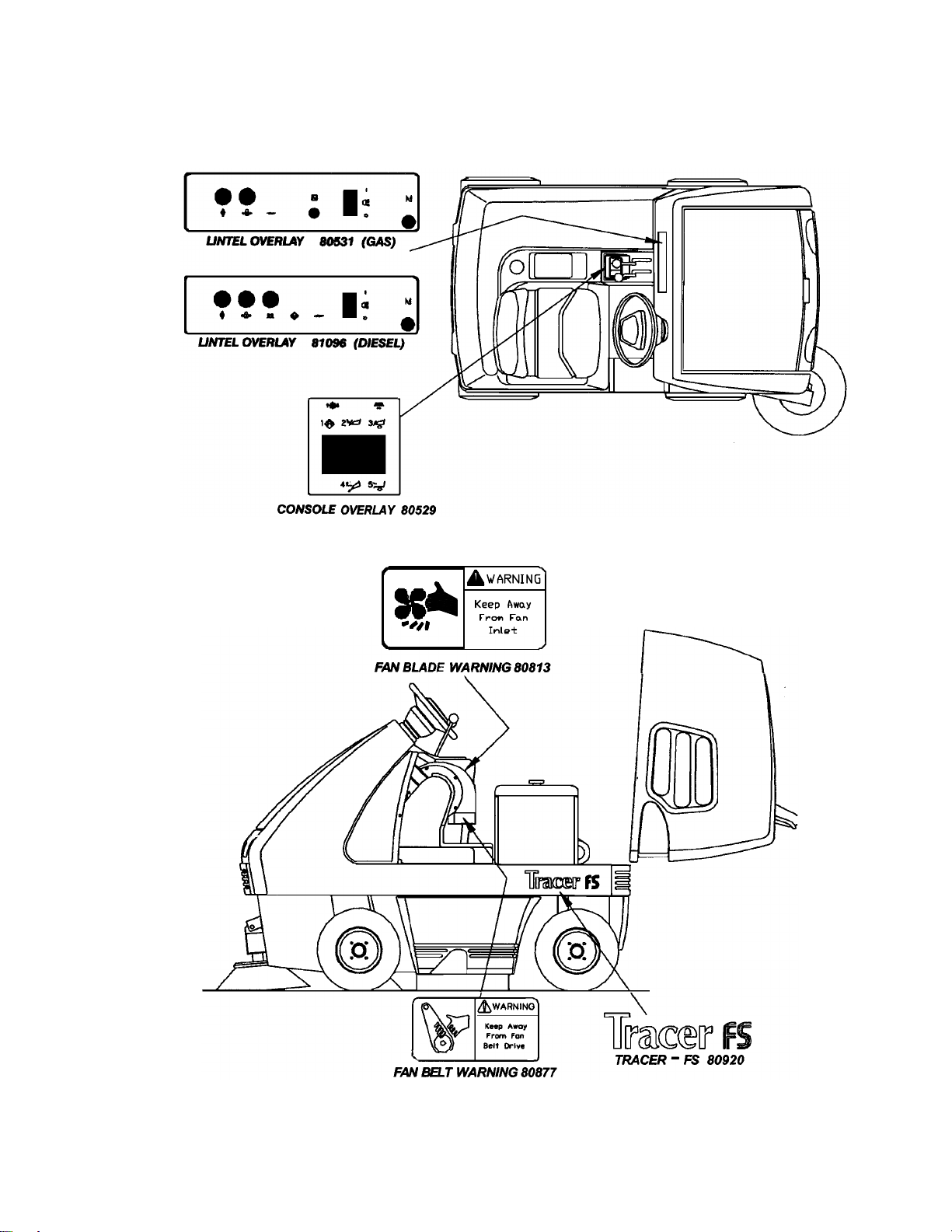
SAFETY LABEL LOCATION
NOTE: These drawings indicate the location of safety labels on the Tracer FS. If, at any time, the labels become
illegible contact your Windsor representative for prompt replacement.
QTFSG/QTFSD 98349 05/15/03
2-3
Page 8
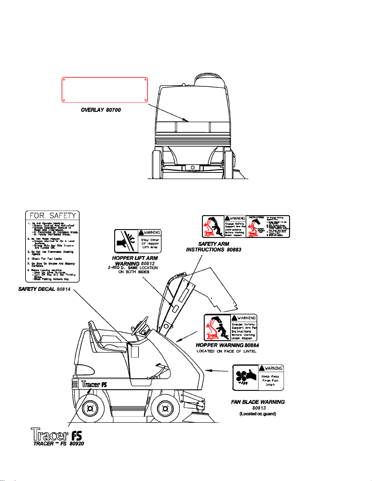
SAFETY LABEL LOCATION
NOTE: These drawings indicate the location of safety labels on the Tracer FS. If, at any time, the labels become
illegible contact your Windsor representative for prompt replacement.
2-4
QTFSG/QTFSD 98349 05/15/03
Page 9
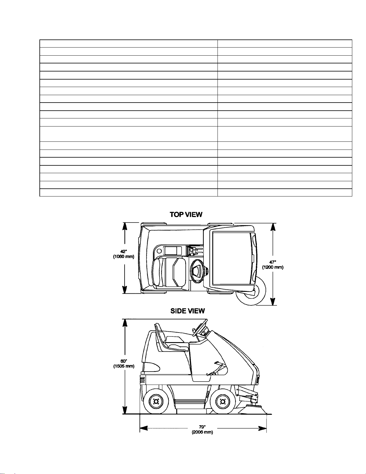
TECHNICAL SPECIFICATIONS
ITEM DIMENSION/CAPACITY
Power Source: Gas 20hp, 2 Cylinder, Liquid-Cooled
Diesel 14hp, 2 Cylinder, Liquid-Cooled
Suspension Floating I-Beam
Maximum Speed 10k/hour
Sweep Path 1200mm
Main Broom 812mm
Main Broom Diameter 355mm
Side Broom 510mm
Hopper Capacity 180 liters
Hopper Dump 1520mm
Dust Control 54ft2 (5m2) pleated filter with exclusive
cyclonic pre-filter
Brakes Dual mechanical disc with parking brake
Steering Rear wheel, rack & pinion
Tires 405mm dia. Pneumatic
Dimensions: Height 1505mm
Weight 1060 lbs.
Length 2006mm
Coverage 12,000m2/hr
QTFSG/QTFSD 98349 05/15/03
3-1
Page 10
CONTROLS
SPECIAL NOTES:
The sound pressure level at the operator’s ear was
measured to be 78 dBA for the QTFSG and 83 dBA for
the QTFSD. This was a nearfield, broad-band
measurement made during normal operation on a
composite tile floor with a white pad. This appliance
contains no possible source of impact noise. The
instantaneous sound pressure level is below 63 Pa.
The weighted root mean square acceleration at the
operator’s arms was measured to be below 2.5m/s
the QTFSG and below 3.2m/s2 for the QTFSD. The
weighted root mean square acceleration at the
operator’s posterior was measured to be below 0.5m/s
for the QTFSG and below 1.3m/s2 for the QTFSD. This
was a tri-axial, third-octave-band measurement made
during normal operation on a composite tile floor. The
measurement and related calculations were made in
accordance with ANSI S3.34-1986.
2
for
2
3-2
QTFSG/QTFSD 98349 05/15/03
Page 11
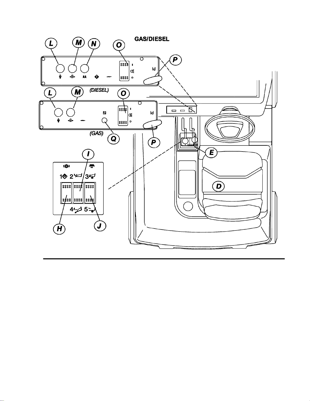
CONTROLS
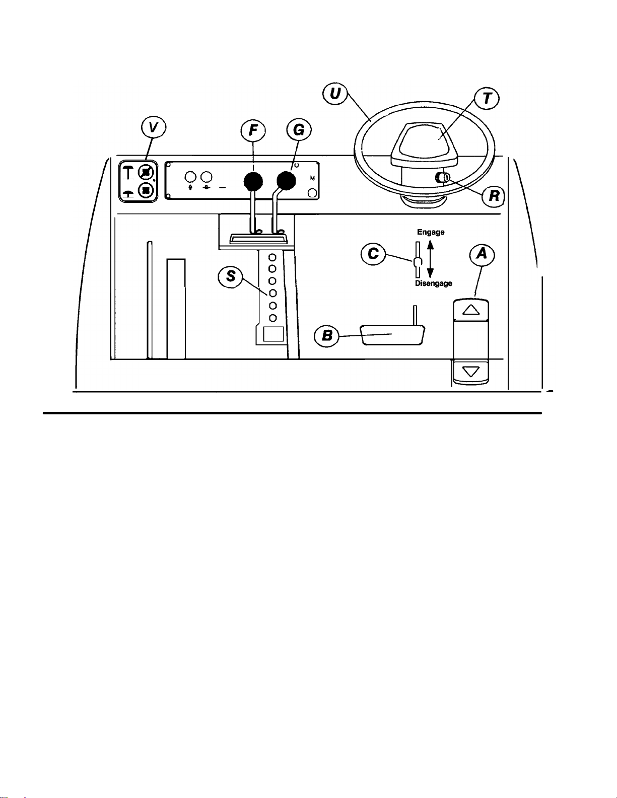
A. Directional Control Pedal
B. Brake Pedal
C. Parking Brake
D. Operator Seat
E. Rear Cover Latch
F. Main Broom Lever
G. Side Broom Lever
H. Filter Shaker Switch
I. Hopper Door Switch
J. Hopper Lift Switch
K. Hopper Safety Arm
L. Engine Temperature Light
M. Oil Pressure Light
N. Engine Glow Plug Light (Diesel
Only)
O. Light Switch
P. Engine Throttle Handle
Q. Choke Cable
R. Key Switch
S. Circuit Breakers
T. Horn Pad
U. Steering Wheel
V. Wet Sweep Bypass
QTFSG/QTFSD 98349 05/15/03
3-3
Page 12

CONTROLS
A - DIRECTIONAL CONTROL PEDAL
This pedal controls the direction of travel and the
speed of the machine.
Slowly pressing the front of the pedal causes the
machine to travel forward. Pressing the rear of the
pedal causes the vehicle to travel in reverse. The
machine speed can be controlled by varying the
pressure on the front or rear of the pedal.
FOR SAFETY: The machine can coast for a short
distance after releasing the directional pedal. Use
the brake pedal to slow or stop the machine.
B – BRAKE PEDAL
This brake operates the disc brakes on the two front
tires. To slow or stop the machine, apply pressure
to the brake pedal.
C – PARKING BRAKE LEVER
The knob located above the brake pedal is the
parking brake knob. To set the parking brake, slide
the parking brake knob up to the top of its slot, then
depress the brake pedal. To release the parking
brake, slide the parking brake knob to the bottom of
its slot. The brake pedal will return to its raised
position.
FOR SAFETY: Always park on a level surface, turn
the machine off, and set the parking brake before
leaving the machine, and before servicing the
machine.
D – OPERATOR SEAT
The operators seat position is adjustable. To
change positions loosen the four lower mounting
bolts and slide the seat to the desired position.
Tighten the four mounting bolts.
E – REAR COVER LATCH
The rear cover latch locks the rear cover in the
closed position. To open the rear cover, push the
latch in and pull the rear cover back. To close the
rear cover, lower it slowly until the latch engages the
floor slot. Do not let the rear cover drop, or damage
to the latch or cover may occur.
FOR SAFETY: When the rear cover is open a
safety switch prevents the operation of the main
broom and vacuum impeller.
F – MAIN BROOM LEVER
FOR SAFETY: The main broom and the vacuum
impeller automatically begin to operate when the
main broom lever is positioned in the forward end of
its slot.
The main broom lever controls the position and the
drive of the main broom. To start the main broom
and lower it to the floor, release the main broom
lever and let it drop to the front end of its slot. To
shut off and raise the main broom, pull the main
broom lever back into its locked position.
G – SIDE BROOM LEVER
FOR SAFETY: The side broom automatically
begins to operate when the side broom lever is
positioned in the forward end of its slot.
The side broom lever controls the position and the
drive of the side broom. To start the side broom and
lower it to the floor, release the side broom lever and
let it drop to the front end of its slot. To shut off and
raise the side broom, pull the side broom lever back
into its locked position.
When parking the machine, always raise the brooms
to prevent the bristles from taking a set.
H – FILTER SHAKER SWITCH
The filter shaker switch operates the dust filter
cleaning system.
3-4
For efficient sweeping the filter must be cleaned on
a regular basis. To clean the filters, pull the Wet
Sweep Bypass knob, then push and hold the filter
shaker switch for 10-20 seconds. Clean the filters
just before dumping the hopper. In very dusty
conditions the filter may need to be cleaned more
frequently.
QTFSG/QTFSD 98349 05/15/03
Page 13

CONTROLS
3-5
I – HOPPER DOOR SWITCH
The hopper door switch opens and closes the
hopper dump door. Pushing the front half of the
hopper door switch closes the hopper dump door.
Pushing the rear half of the switch opens the hopper
dump door. A beeper sounds when the door is in
the closed position. Sweeping should not be
attempted when the hopper door is closed.
J – HOPPER LIFT SWITCH
The hopper lift switch is used to raise and lower the
hopper during dumping operations. To raise the
hopper, press and hold the front half of the hopper
lift switch until the hopper has raised to the desired
height. Then release the switch. To lower the
hopper, press and hold the rear half of the hopper lift
switch until the hopper lowers to the normal
sweeping position.
FOR SAFETY: The hopper lift switch will not raise
or lower the hopper if the key switch is in the off
position.
K – HOPPER SAFETY ARM
The hopper safety arm is used to support the hopper
in the raised position. The safety arm should be
used whenever inspection or service is performed
under the hopper. Do not rely on the hydraulic
cylinder to keep the hopper raised.
L – ENGINE TEMPERATURE LIGHT
The engine temperature light indicates when the
engine is overheating. If the light comes on, stop
the engine immediately and determine the cause.
Failure to stop the engine will result in engine
damage. Some causes of engine overheating are a
clogged radiator, clogged cooling fins in the radiator,
loose fan belt or other engine malfunction. Consult
your Engine Owners guide to help determine the
problem.
M – OIL PRESSURE LIGHT
The engine oil pressure light indicates inadequate
engine oil pressure. If the light comes on, stop the
engine immediately and determine the cause.
Failure to stop the engine will result in engine
damage.
N – ENGINE GLOW PLUG LIGHT
(DIESEL ONLY)
The glow plug light is a time-controlled light that
allows the glow plugs to heat up sufficiently before
cranking the engine. When the ignition switch is
turned clockwise to the “RUN” position, the light will
come on. After 5-30 seconds, depending on
temperature, the light will go off. Then the engine
can be cranked with the ignition switch.
O – LIGHT SWITCH
Raised hopper may fall. Engage hopper safety
arm before working under hopper.
QTFSG/QTFSD 98349 05/15/03
The light switch operates the headlights and
taillights.
P – THROTTLE
The throttle is an adjustable, lockable tee-handle.
The handle is unlocked by turning counterclockwise, and locked by turning clockwise. Start
the engine with the throttle pushed all the way in.
When the engine has adequately warmed up, unlock
and pull the throttle all the way out and lock. This
will set the engine at the maximum governed speed.
The throttle may be adjusted and locked anywhere
between idle and max. if desired. Consult engine
service guide.
Page 14

CONTROLS
Q – CHOKE (GAS ONLY)
By pulling this knob out, the choke is engaged for
cold starting. To release choke, push the knob in.
R – KEY SWITCH
The key switch controls starting and electrical power
for most machine functions. To start the machine,
turn the key clockwise past the “RUN” position to the
crank position. After engine has started release key.
(For starting diesel engines, see “Glow Plug Light”).
To stop engine, turn key counter-clockwise.
S – CIRCUIT BREAKERS
The circuit breakers are circuit protection devices
designed to interrupt the flow of current in the event
of an electrical overload. When tripped, the circuit
breakers must be reset by pressing the exposed
button on the face of the affected circuit breaker. If
the circuit breaker continues to trip, the cause of the
electrical overload should be found and corrected.
The following chart shows the circuit breakers and
the components they protect.
GAS:
DEVICE RATING COMPONENT
PROTECTED
CB-1 30A Voltage Regulator
CB-2 15A Igniter, Fuel Pump,
Oil Pressure Lamp,
Water Temp. Lamp
CB-3 15A Side Broom Valve,
Head Lamps, Tail
Lamps, Horn
CB-4 15A Options
CB-5 15A Hopper Dump Door,
Shaker Motor, Hour
Meter, Hopper
Raise/Lower Valves
DIESEL:
DEVICE RATING COMPONENT
PROTECTED
CB-1 30A Glow Plugs
CB-2 30A Starter Relay, Oil
Pressure Lamp,
Water Temp. Lamp,
Glow Plug Lamp,
Optional Charge
Light, Optional Air
Registration Light
CB-3 15A Side Broom Valve,
Head Lamps, Tail
Lamps, Horn,
CB-4 15A Options
CB-5 15A Hopper Dump Door,
Shaker Motor, Hour
Meter, Hopper
Raise/Lower Valves
T – HORN PAD
The horn pad is located on the steering wheel. The
horn is activated by pressing on any area of the horn
pad.
U – STEERING WHEEL
The steering wheel controls the two rear wheels.
The machine is highly receptive to the movement of
the wheel. Operators should use care until they
become experienced in driving the machine.
V – WET SWEEP BYPASS
By pulling this knob out, vacuum is cut off from filter
and hopper. To prevent damage to filter caused by
moisture, pull knob out when sweeping through
puddles. To maximize filter cleaning, pull knob out
before pressing filter shaker switch.
3-6
QTFSG/QTFSD 98349 05/15/03
Page 15

OPERATIONS
3-7
BEFORE OPERATING THE FS:
1. Complete the machine data sheet on page 2.
2. Read this manual carefully before operating or
servicing the machine.
Do not operate machine unless Operation
manual is read and understood.
3. Carefully read the Owner’s Manual that is
supplied for your gas or diesel machine.
REFERENCE FOR GAS ENGINE:
Kawasaki FD620D – Owners Manual
REFERENCE FOR DIESEL ENGINE:
Lombardini LDW series – Use, Maintenance
4. Check oil and engine fuel in the machine. See
engine Owner’s manual for complete filling
instructions.
5. Check the hydraulic fluid level in the hydraulic
power unit. See hydraulics in the maintenance
section.
6. Check the main and side broom for correct
adjustment. See brooms in the maintenance
section.
STARTING THE MACHINE
FOR SAFETY: use caution when backing machine.
Do not carry riders on the machine. Always follow
basic safety and traffic rules. Go slow on slippery
surfaces and grades.
1. The operator should be sitting on the seat with
a foot on the brake pedal or with the parking
brake on. The directional pedal should be in
neutral.
TO SWEEP
Plan the sweeping pattern in advance. For efficient
operation, the sweeping runs should be long with as
little stopping and starting as possible. Overlap the
brush paths and complete an entire section at one
time.
Use the side broom to pull debris from areas near
walls or obstructions. The side broom is also useful
for extending the sweeping paths on long runs. If
the area to be swept is very dusty, the side broom
should be raised to prevent dust clouds.
Oversized debris that can inhibit sweeping
operations should be picked up by hand. This
includes large cartons and items that could become
tangled in the brooms, such as wire or banding
material.
The machine is very responsive. Avoid turning the
steering wheel too sharply when the machine is in
motion. Avoid sudden turns except in an
emergency.
1. Put the main broom lever in the forward position
to lower the main broom.
2. Put the side broom lever in the forward position
to lower the side broom.
NOTE: The main broom and side broom lever
indicators are color-coded green.
3. Make sure that the hopper door is open. A
beeper will sound if the hopper door is not
open.
4. Sweep as required.
OPERATING ON GRADES
FOR SAFETY: Before starting machine, make sure
that all safety devices are in place and operating
properly.
2. Turn the key switch clockwise to the “ON”
position.
3. Drive the machine to the area where sweeping
is to begin.
QTFSG/QTFSD 98349 05/15/03
Operate the machine slowly on grades. Use the
brake pedal to control the machine speed.
NOTE: When operating machine, go slowly on
grades and slippery surfaces.
Page 16

OPERATIONS
STOPPING THE MACHINE
1. Remove foot from the directional pedal and
apply the brake.
2. Raise and turn off the brooms by pulling the
main and side broom levers back to the rear
locked position.
3. Set the parking brake.
4. Turn the key switch counterclockwise to the off
position. Remove the key.
STORING THE MACHINE
When storing the machine for extended periods of
time, the following procedure must be followed to
lessen the chance of rust, sludge, or other
undesirable deposits from forming.
1. Empty the hopper.
2. Raise the main broom and the side broom.
3. Park the machine in a cool, dry area.
TO ENGAGE THE HOPPER SAFETY ARM
Raised hopper may fail. Engage hopper safety
arm before working under hopper.
1. Set the machine parking brake.
FOR SAFETY: Before leaving or servicing machine;
stop on level surface, set parking brake, turn OFF
machine and remove key.
2. Raise the hopper.
3. Unhook the safety arm and swing it down into
position over the safety arm retainer. Do not let
the safety arm drop into position.
4. Slowly lower the hopper until the safety arm is
secure.
4. Remove or change the batteries for 4 hours,
once every three months.
DUMPING THE HOPPER
NOTE: The hopper dump switches are numbered
and color-coded. The filter shaker is shown in
yellow and hopper functions are shown in red.
1. Drive the machine to the dump site or dumpster.
2. The correct sequence for dumping the hopper is
shown by following the numbers on the switch
panel.
1. Clean the filter by pressing the filter shaker
switch for 10-20 seconds.
2. Close the hopper door by pushing and
releasing the front half of the hopper door
switch. The beeper will sound.
3. Press and hold the front half of the hopper
lift switch and raise the hopper to a height
that will clear the dumpster, then release the
switch. Drive forward slowly until the hopper
is positioned above the dumpster.
4. Dump the hopper by pressing and then
releasing the rear half of the hopper door
switch. After dumping, back the machine
slowly away from the dumpster.
5. Lower the hopper by pressing and holding
the rear half of the hopper lift switch.
Make sure that the lower end of the safety arm is
correctly held in the retainer on the machine
frame.
3-8
QTFSG/QTFSD 98349 05/15/03
Page 17

OPERATIONS
TO DISENGAGE THE HOPPER SAFETY ARM
1. Raise the hopper.
2. Place the safety arm in its storage position on
the inside of the hopper lift arm.
3. Lower the hopper.
TOWING OR PUSHING MACHINE
Gas and diesel powered machines may be pushed
or towed easily by bypassing the transmission. To
do this raise the rear cover and remove the belt
guard. Locate the transmission. On the rear of the
transmission is a plunger valve. Push the valve in
as far as possible and pivot up the tow bar valve just
next to the valve. This bar is supplied to lock the
valve in the “IN” position. The machine can now be
easily pushed or towed up to 4 mph (7
kilometers/hr).
Do not exceed 4 mph (7 kilometers/hr) as
damage to the transmission may result.
When towing is complete, slide tow valve bar out of
the way to release valve.
TO JACK UP MACHINE
1. Empty and lower the hopper.
2. Turn the key switch off and set the parking
brake.
FOR SAFETY: Before leaving or servicing machine;
stop on level surface, set parking brake, turn off
machine and remove key.
3. Block the tires that are not being raised to
prevent the machine from rolling.
FOR SAFETY: When servicing machine, block
machine tires before raising machine.
4. Use a jack of adequate capacity, raise the
machine using the designated jack locations.
FOR SAFETY: When servicing machine, use hoist
or jack of adequate capacity, jack machine at
designated jack locations only. Block machine with
jack stands when raised.
5. When the machine is raised, use jack at the
designated jack locations.
FOR SAFETY: Block machine at designated jack
locations with jack stands when raised.
6. Slowly lower the machine onto the jack stands.
7. Be sure that the machine is secure.
8. Service or inspect the machine as required.
9. When finished working on the machine, raise the
machine off the jack stands.
10. Remove the jack stands.
11. Lower the machine to the floor. Remove the
blocks from the tires.
MACHINE JACKING
The machine may be jacked up for service or
inspection by using the specified jack locations.
Always block the tires when jacking up the machine.
The right front jack location is the base of the side
broom, just ahead of the right tire.
The left front jack location is the lower front frame
channel just ahead of the left front tire.
The rear jack location is the steel beam mount
located at the rear of the machine, centered under
the plastic bumper.
QTFSG/QTFSD 98349 05/15/03
MACHINE TIE-DOWNS
There is a tie-down location at each corner of the
machine. The front attach points are the frame
cutouts located directly above each front tire. The
rear attach points are the right and left lower flange
of the frame channels, where they join the rear
bumper. An alternate single rear attach point is
around the pivot of the rear axle beam, located at
the center of the machine behind the rear jack point.
NOTE: When transporting the machine on a trailer
or in a truck, in addition to tie-downs, be sure to set
the machine parking brake, and block the tires to
prevent the machine from rolling.
3-9
Page 18

MAINTENANCE
HYDRAULIC FLUID
Hydraulic fluid is used with the hydraulic pump to
operate the hopper lift system and the side broom
motor. The condition of the hydraulic fluid plays a
large part in determining the life of the hydraulic
system.
The hydraulic fluid used in the Tracer Gas/Diesel
powered Floor Sweeper is Chevron 400 15W40. If a
different hydraulic fluid is used, it must closely match
the viscosity specification below.
SUS @ 100” (38º C) 404-445
SUS @ 210” (38º C) 78-84
This specification has a flat viscosity curve (high
viscosity index). This means the thickness of the oil
stays relatively constant over a wide temperature
range. DO NOT use Automatic Transmission Fluid.
NOTE: The hydraulic components in the machine
rely on system hydraulic fluid for lubrication. Dirty or
contaminated fluid accelerates wear and
malfunctions, and reduced component life.
HYDRAULIC FLUID RESERVOIR
5. Remove bolts (4) in feet of reservoir.
6. Shift reservoir forward so that short leg of
reservoir drops down and rests on lower frame.
7. Remove upper hydraulic hose from reservoir.
8. Lift reservoir out of frame and rest on outer
frame with open port above oil level.
9. Tilt reservoir back and remove last hose.
10. Reservoir may be emptied by pouring fluid out of
ports.
11. The fluid strainer may be removed for inspection
and to speed fluid drainage.
NOTE: Do not overfill the reservoir. Expansion of
the hydraulic fluid when heated to the normal
operating temperature can cause fluid to spill from
the reservoir, or cause damage to the component.
If the reservoir is overfilled, use a suction type
device to draw the excess hydraulic fluid from the
reservoir.
HYDRAULIC FLUID LEAKS
Pressurized hydraulic fluid spraying from a very
small hole can be very hard to see. Do not use
hands to locate the leak. Use a piece of cardboard
as shown below to find leaks.
The hydraulic fluid reservoir is located below the
broom levers inside the machine. To check the fluid
level remove the fill cap to read the dipstick attached
to the cap.
NOTE: Do not overfill reservoir. Expansion of the
hydraulic fluid when heated to the normal operating
temperature can cause fluid to spill from the
reservoir, or cause damage to the component.
The oil in the reservoir should be replaced every 500
hours of use. To drain hydraulic reservoir:
1. Turn off machine and set parking brake.
FOR SAFETY: Before leaving or servicing the
machine, stop on level surface, apply parking brake,
turn off machine and remove key.
2. Raise rear cover.
3. Disconnect batteries from machine.
4. Remove impeller.
A – Hydraulic Pump
When servicing machine, use a sheet of
cardboard to locate leaking hydraulic fluid under
pressure. Keep eyes and hands clear of leaks.
Escaping hydraulic fluid under pressure can
cause severe injury.
A – Hydraulic Line
B – Cardboard
C – Pinhole Leak
4-1
QTFSG/QTFSD 98349 05/15/03
Page 19

MAINTENANCE
HYDRAULIC FILTER
The hydraulic filter keeps the machines hydraulic
system clean to a level of 10 microns. The hydraulic
fluid filter is located just inside the left rear frame.
The filter should be changed every 500 hours.
TO REPLACE FILTER ELEMENT:
1. Stop the engine and set the parking brake.
2. Open the seat support.
3. Unthread and discard the hydraulic fluid filter
element.
4. Apply a thin coat of hydraulic fluid to the seal of
the new hydraulic fluid filter element.
5. Thread and hand tighten the new hydraulic fluid
filter element on the filter head.
6. Close the seat support.
7. Operate the machine and check for leaks.
Correct any leaks found.
8. Check the hydraulic fluid reservoir level and fill
as required.
DIRECTIONAL CONTROL SYSTEM
(Refer to the Electrical Control Group in the
Parts section)
The directional control system controls the direction
and speed of the machine. The system is made up
of the directional pedal, the throttle box, the
transistorized controller and contactors. The
controller, located in the electrical drive
compartment, is sealed and can only be serviced by
trained service personnel.
Do not use a pressure washer to clean the inside
of the electrical drive compartment.
When servicing machine, disconnect battery
connections before working on machine.
DIRECTIONAL CONTROL PEDAL ADJUSTMENT
(Refer to the Console Group in the Parts section)
The directional control pedal is designed to prevent
driver fatigue. However if a different pedal angle is
preferred, these directions should be followed.
1. Raise rear cover.
2. Disconnect batteries from machine.
3. Locate and remove the directional control pedal
stop bolt.
4. Locate the linkage rod beneath the directional
control pedal.
5. Adjusting the length of the linkage rod controls
the pedal angle. Shortening the linkage rod
causes the pedal to have a flatter angle with the
floor. Lengthening the linkage rod causes the
pedal to have a steeper angle.
6. To change the length of the linkage rod,
disconnect the upper end of the linkage rod from
the forward/reverse arm.
7. Loosen the locking nuts on both ends of the
threaded portion of the linkage rod.
8. Turning the balljoint changes the length of the
linkage rod, be sure that there is a minimum of
5/16” of threaded rod engaged in each of the
balljoints.
9. When the new length is established, reconnect
the upper balljoint to the forward/reverse arm.
10. Tighten the two locking nuts on the threaded
portion of the linkage rod.
11. Reposition the directional foot pedal stop bolt.
12. The stop bolt must be adjusted so that the
directional foot pedal comes in contact with the
stop while there is still a small amount of travel
remaining in the throttle arm. This is done to
prevent heavy foot pressure from damaging the
throttle unit.
THROTTLE “NEUTRAL POSITION”
ADJUSTMENT (Refer to the Console Group in
the Parts section)
The throttle is automatically returned to its neutral
position by a spring centering system. If the
machine tends to creep forward or reverse when the
operators foot is removed from the directional foot
pedal, the throttle “neutral position” may require
adjustment as described below:
1. Turn off machine and set parking brake.
2. Raise the rear cover.
3. Disconnect the batteries from the machine.
4. Remove the drive motor dust cover.
5. Locate the throttle and spring centering
assembly.
6. Disconnect the linkage rod from the throttle arm.
7. With the throttle arm free, the throttle will return
to its neutral position using its internal centering
spring.
8. Position the linkage rod balljoint over the hole in
the throttle arm. The balljoint should slide into
the hole without repositioning the throttle arm.
9. If required, shorten or lengthen the linkage rod
until proper engagement occurs.
10. Reattach linkage rod to the throttle arm.
11. Install the drive motor dust cover.
12. Connect batteries.
13. Lower hopper.
QTFSG/QTFSD 98349 05/15/03
4-2
Page 20

MAINTENANCE
MAIN BROOM (Refer to the Main Broom Group
and Main Broom Lift Group in the Parts section)
FOR SAFETY: The main broom and the vacuum
impeller automatically begin to operate when the
main broom lever is positioned in the forward end of
its slot.
The main broom spans the width of the machine,
and sweeps debris into the hopper. Inspect the
main broom daily for wear or damage. Remove any
obstructions found in the main broom chamber, main
broom drive hub or idler hub.
The main broom should be replaced when the
remaining bristles measure 5/8 “ (16mm) or less in
length.
NOTE: All original equipment brooms are equipped
with “Perform Alert™”. This feature tells the
operator when it is time to replace the main broom.
“Perform Alert™” brooms have bright yellow tufts
located on each end of the broom. These tufts are
pre-trimmed to indicate the length of a worn out
broom. When the main body of the broom wears to
a length that matches the yellow tufts, the broom
should be replaced.
Always check the main broom pattern when
installing a new broom.
TO REMOVE THE MAIN BROOM
TO INSTALL THE MAIN BROOM
1. Turn off machine and set parking brake.
FOR SAFETY: Before leaving or servicing the
machine, stop on level surface, apply parking brake,
turn off machine and remove key.
2. Raise rear cover.
3. Disconnect batteries from machine.
4. Lower the main broom lever.
5. Open right side broom door.
6. If replacing a worn broom, turn the main broom
adjustment knob so that the broom drive hub is
raised to a position that will allow a new broom
to easily slide onto the broom drive hub.
7. Slide the new brush into the broom chamber.
8. Hold the broom by the core and rotate the
broom counter-clockwise while pushing the
broom onto the drive hub. Make sure that the
broom is fully seated onto the drive hub before
attempting to install the idler arm.
9. Locate the idler arm. Align the tabs on the idler
hub with the slots on the main broom core.
Slide the idler into the main broom core, the
position the upper right end of the idler arm onto
the two locator pins.
10. Replace and tighten the D-ring retainer.
11. Close the broom door.
12. Check the main broom floor pattern and adjust
as necessary.
1. Turn off machine and set parking brake.
FOR SAFETY: Before leaving or servicing the
machine, stop on a level surface, apply parking
brake, turn off the machine and remove key.
2. Raise rear cover.
3. Disconnect batteries from machine.
4. Lower the main broom lever.
5. Open the right side broom door.
6. Remove the idler arm D-ring retainer.
7. Remove the main broom idler arm.
8. Grasp the broom by the core and remove.
4-3
QTFSG/QTFSD 98349 05/15/03
Page 21

4-4
CHECKING AND ADJUSTING THE MAIN BROOM
PATTERN
1. Using chalk, or similar material, coat and area of
the floor that is flat and smooth. If a suitable
material is not available, run the broom for two
minutes during the following test.
2. With the main broom raised, position the
machine so that the main broom is directly over
the chalked area.
3. Apply the parking brake to prevent the machine
from moving.
4. Lower the main broom to the floor for 10-15
seconds.
5. Raise the main broom, release the parking
brake, and back the machine away from the test
area.
6. Observe the pattern that the main broom left on
the floor. The pattern should be 1 to 1-1/2
inches (25.4 to 38.1mm) wide. The pattern
should not be tapered (wider at one end than the
other).
7. To adjust the width of the pattern, locate the
main broom adjustment knob, and loosen the
locking wing nut.
8. If the pattern is too wide, rotate the adjustment
knob clockwise to raise the broom. If the pattern
is too thin, rotate the adjustment knob,
counterclockwise to lower the broom. Tighten
the locking wing nut.
9. Check the broom pattern again. Repeat the
procedure until the pattern is correct.
A – Main Broom Pattern
B – 1 to 1-1/2” (25.4 to 38.1mm)
NOTE: If one end of the main broom pattern is more
than 1/2” (12.7mm) wider than the other end,
perform the following leveling procedure.
MAINTENANCE
A – Main Broom Adjustment Knob
The adjustable bearing block used to correct a
tapered broom pattern is located just inside the right
broom door. Only the right side of the broom can be
raised or lowered to correct the pattern. Before
attempting the following adjustment, determine if the
right side of the broom needs to be raised or
lowered to correct the tapered pattern.
1. Turn off machine and set parking brake.
FOR SAFETY: Before leaving or servicing the
machine, stop on level surface, apply parking brake,
turn off machine and remove key.
2. Raise rear cover.
3. Disconnect batteries from machine.
4. Open the right side broom door.
5. Remove the main broom.
6. Locate the plastic main broom bearing block just
inside the right broom door. Loosen the bearing
block retainer bolts.
7. Slide the bearing block up or down to correct the
tapered pattern condition.
8. Tighten the bearing block retaining bolts.
9. Replace the main broom, and repeat the pattern
test procedure. Readjust if necessary to
eliminate the tapered pattern condition.
QTFSG/QTFSD 98349 05/15/03
Page 22

MAINTENANCE
SIDE BROOM (Refer to the Side Broom Group in
the Parts section)
FOR SAFETY: The side broom automatically
begins to operate when the side broom lever is
positioned in the forward end of its slot.
The side broom is used to clean debris sway from
curbs and walls, and sweep it into the path of the
main broom. Inspect the side broom daily for wear
or damage. Remove any string, wire or banding
found wrapped around the side broom, side broom
hub, or shaft.
The side broom should be replaced when the
remaining bristles measure 2-1/2 inches (65 mm) or
less in length.
NOTE: All original equipment brooms are equipped
with “Perform Alert™”. This feature tells the
operator when it is time to replace the side broom.
“Perform Alert™” brooms have bright yellow tufts
located around the outside edge of the broom.
These tufts are pre-trimmed to indicate the length of
a worn out broom. When the main body of the
broom wears to a length that matches the yellow
tufts, the broom should be replaced.
TO REMOVE THE SIDE BROOM
1. Turn off machine and set parking brake.
5. Slide the side broom onto the side broom motor
shaft.
6. Install the side broom retaining pin and the
retaining pin locking clip.
7. Adjust the side broom if necessary
The side broom should contact the floor in an area
as shown below. One third to one half of the side
broom bristles should contact the floor when the
broom is down.
ADJUSTING THE SIDE BROOM
1. Raise the hopper.
2. Engage safety arm.
FOR SAFETY: Before leaving or servicing machine,
stop on level surface, apply parking brake, turn off
machine and remove key.
2. Raise rear cover.
3. Disconnect batteries from machine.
4. Raise the side broom lever.
5. Remove the locking clip from the side broom
retaining pin.
6. Push up on the base of the side broom to relieve
the tension on the retaining pin, then remove the
retaining pin.
7. Slide the side broom off the side broom motor
shaft.
TO INSTALL THE SIDE BROOM
1. Turn off machine and set parking brake.
FOR SAFETY: Before leaving or servicing machine,
stop on level surface, apply parking brake, turn off
machine and remove key.
2. Raise rear cover.
3. Disconnect batteries from machine.
4. Raise the side broom lever.
Raised hopper may fall. Engage hopper safety
arm.
3. Turn off machine and set parking brake.
FOR SAFETY: Before leaving or servicing machine,
stop on level surface, apply parking brake, turn off
machine and remove key.
4. Raise rear cover.
5. Disconnect batteries from machine.
6. Lower the side broom lever.
7. Place a block or similar support under the side
broom to relieve the tension in the lift cable.
8. Locate the side broom adjustments links
located just above the side broom, and remove
the retaining pin passing through both
adjustment links.
9. Reposition the two adjustment links to move the
side broom up or down as required, and replace
the retaining pin.
4-5
QTFSG/QTFSD 98349 05/15/03
Page 23

MAINTENANCE
4-6
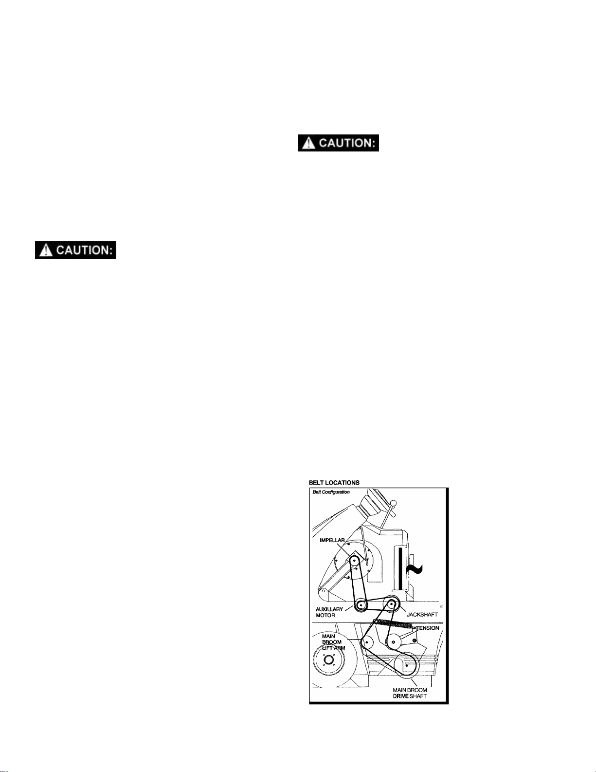
TRANSMISSION JACKSHAFT BELT
The transmission belt transfers power from the
engine to the transmission jackshaft on the gasoline
machines and from the engine jackshaft to the
transmission jackshaft on the diesel powered
machines.
TO REPLACE BELT
1. Turn off machine and set parking brake.
FOR SAFETY: Before leaving or servicing machine,
stop on level surface, apply parking brake, turn off
machine and remove key.
2. Raise rear cover.
3. Disconnect batteries from machine.
4. Remove the belt guard cover.
5. Remove the tension spring for the idler on the
transmission drive belt. Loosen tension on
impeller belt.
6. Loosen, but do not remove the four bolts in the
base of the shaft mounting bracket.
7. Slide mounting bracket toward engine to create
slack in the belt.
8. Loosen, but do not remove 4 bolts in the bases
of the rear jackshaft mount and pump mount
bracket.
9. Loosen tensioning nut and bolt on the rear of
rear jackshaft mount. Slide rear jackshaft mount
away from engine.
10. Remove the bolts retaining the bearings on
transmission jackshaft.
11. Lift the jackshaft and bearings from the mount
and remove the transmission drive belt, then the
transmission jackshaft belt.
12. Remove the bolts retaining the bearing on the
rear jackshaft. Remove the belt controller rod.
13. Loosen bearing collars on rear jackshaft
bearings.
14. Remove first the main broom belt, then the
pump drive belt.
15. Slide the rear jackshaft outward to disengage
the pump coupling, then lift the shaft up to
remove drive belt in reverse order.
16. Reinstall belt in reverse order.
ADJUSTING THE JACKSHAFT BELT
Proper alignment is important for all belts on
Tracer machines. To properly align the
transmission jackshaft belt:
Repeat Steps 1-8 from above then:
9. Move the transmission jackshaft belt off its
pulley and loosen the setscrew in the pulley.
10. Using a straightedge between the pulleys to be
aligned, move the pulley left or right on it’s shaft
until proper alignment is established.
11. After this adjustment, check the transmission
belt alignment.
12. Reverse steps 1-8.
13. If jackshaft belt idler pulley does not center on
belt, adjust by adding or removing washers
behind the idler pulley.
TRANSMISSION BELT
The transmission belt transfers power from the
transmission jackshaft to the transmission.
TO REPLACE BELT
1. Repeat steps 1-10.
11. Lift the jackshaft and bearings from the mount
and remove the transmission belt off the end of
shaft.
REAR JACKSHAFT (PUMP DRIVE) BELT
The rear jackshaft belt transfers power from
transmission jackshaft to rear jackshaft.
TO REPLACE BELT
1. Turn off machine and set parking brake.
FOR SAFETY: Before leaving or servicing machine,
stop on level surface, apply parking brake, turn off
machine and remove key.
2. Raise rear cover.
3. Disconnect battery from machine.
4. Remove the belt guard cover.
5. Remove belt controller rod from rear jackshaft
mount and take main broom drive belt off double
pulley located on rear jackshaft.
6. Loosen, but don’t remove 4 bolts in base of rear
jackshaft mount and pump mount.
7. Loosen tensioning nut and bolt at rear jackshaft
mount, and slide mount away from engine.
8. Remove rear jackshaft belt.
QTFSG/QTFSD 98349 05/15/03
Page 24
MAINTENANCE
TO ALIGN BELT
1. Repeat steps 1-7
8. Loosen tension on impeller drive pulley on end
of transmission jackshaft.
9. Slide pulley side to side on shaft to make proper
alignment.
10. Retighten setscrews in pulley.
11. Reverse Steps 1 –7.
MAIN BROOM BELT (Refer to Main Broom Group
in the Parts section)
The main broom belt transfers power from the rear
jackshaft to the main broom pulley. Check the belt
condition and tension every 200 hours of operation.
The main broom and vacuum impeller
automatically begin to operate when the main
broom lever is positioned in the forward end of
its slot.
REPLACING AND ADJUSTING MAIN BROOM
BELT
1. Turn off machine and set parking brake.
FOR SAFETY: Before leaving or servicing machine,
stop on level surface, apply parking brake, turn off
machine and remove key.
2. Raise rear cover.
3. Disconnect batteries from machine.
4. Remove the belt guard.
5. Be sure main broom lift lever is in the raised
position. Remove the belt controlling rod from
rear jackshaft mount.
6. Remove belt from pulleys.
7. Install new belt and reinstall belt controlling rod.
VACUUM IMPELLER BELT (Refer to the Impeller
Group in the Parts section)
The impeller belt transfers power from the auxiliary
motor to the impeller. Check the belt condition and
tension every 200 hours of operation.
The main broom and vacuum impeller
automatically begin to operate when the main
broom lever is positioned in the forward end of
its slot.
REPLACING AND ADJUSTING THE VACUUM
IMPELLER BELT
1. Turn off machine and set parking brake.
FOR SAFETY: Before leaving or servicing machine,
stop on level surface, apply parking brake, turn off
machine and remove key.
2. Raise rear cover.
3. Disconnect batteries from machine.
4. Remove the belt guard and the side filler panel.
5. Loosen the auxiliary motor base mounting bolts.
6. Slide the auxiliary motor back and remove the
jackshaft belt.
7. Pull the auxiliary motor forward to tension the
jackshaft belt. The belt has proper tension when
the belt deflects 1/4 inch (6 mm) from a force of
6 Ibs (3 kg) applied at the midpoint of the belt.
8. While keeping the motor and jackshaft pulleys
aligned, tighten the auxiliary motor base
mounting bolts.
9. Replace the main broom belt.
10. Replace the side filler panel and the belt guard.
TO ALIGN BELT
Repeat steps 1-7 under rear jackshaft (Pump Drive)
belt.
8. Loosen set screws in double pulley located on
the rear jackshaft.
9. Slide pulley side to side to align with main broom
drive pulley below.
10. Retighten setscrews in pulley.
11. Reverse Steps 1 –7.
NOTE: This adjustment may require realignment of
the rear jackshaft belt.
4-7
QTFSG/QTFSD 98349 05/15/03
Page 25

MAINTENANCE
IMPELLER BELT
The impeller belt transfers power from transmission
jackshaft to impeller.
1. Turn off machine and set parking brake.
FOR SAFETY: Before leaving or servicing machine,
stop on level surface, apply parking brake, turn off
machine and remove key.
2. Raise rear cover.
3. Disconnect batteries from machine.
4. Remove the belt guard cover.
5. Release tension on impeller belt using tension
bolt under impeller arm.
6. Repeat Steps 5 and 6 under Rear Jackshaft
(Pump Drive) Belt.
7. Remove rear jackshaft belt from front pulley.
8. Remove impeller belt.
9. Replace belt and reverse Steps 1 –6.
TO ALIGN BELT
6. Loosen 4 bolts holding transmission case to
mount.
7. Locate tensioning bolt at top of transmission
mount. Tighten or loosen bolt as needed to
properly tension chain.
8. Tighten 4 mounting bolts in transmission body.
If alignment of the chain and sprockets becomes
necessary, the alignment is accomplished by moving
the entire differential assembly side to side.
TO REALIGN
1. Raise the hopper and engage the hopper safety
arm.
Raised hopper may fall. Engage hopper safety
arm.
2. Turn off machine and set parking brake.
FOR SAFETY: Before leaving or servicing machine,
stop on level surface, apply parking brake, turn off
machine and remove key.
1. Loosen impeller belt, using the tensioning bolt
under the impeller arm.
2. Loosen set screws in the impeller pulley.
3. Slide the pulley side to side to make proper
alignment.
4. Tighten set screws in pulley.
5. Retighten impeller belt.
DIFFERENTIAL DRIVE CHAIN (Refer to the
Differential Group in the Parts section)
The differential drive chain transfers power from the
output sprocket of transmission to differential
sprocket. Check the chain condition and tension
every 200 hours of operation.
REPLACING AND ADJUSTING DIFFERENTIAL
DRIVE CHAIN
1. Raise the hopper and engage the hopper safety
arm.
2. Turn off machine and set parking brake.
FOR SAFETY: Before leaving or servicing machine,
stop on level surface, apply parking brake, turn off
machine and remove key.
3. Remove rear cover.
4. Disconnect battery from machine.
5. Remove the drive motor dust cover.
6. Loosen all four locking on bearings supporting
the differential.
7. Loosen the set screws in the two brake disks.
8. Loosen but don't remove the hardware attaching
the bearing flanges to the frame.
9. Make sure there is little tension on the drive
chain. Gently slide the differential in it's bearing
to restore proper alignment.
NOTE: The brake disks must remain stationary
while the differential shafts move in them.
10. Reverse Steps 1-8. Follow tensioning
instructions above.
NOTE: After aligning the differential the small
sprockets at each end of the differential may need to
be realigned with the wheel sprockets. If so, loosen
setscrews in small sprockets and slide on differential
shaft until aligned. Retighten setscrews.
3. Raise rear cover.
4. Disconnect batteries from machine.
5. Remove the drive motor dust cover.
QTFSG/QTFSD 98349 05/15/03
4-8
Page 26
MAINTENANCE
DRIVE WHEEL CHAIN (Refer to the Front Wheel
Group in the Parts section)
The drive wheel chain transfers power from the
differential shaft to the drive wheels. Check the
chain condition and tension every 200 hours of
operation.
REPLACING AND ADJUSTING THE DRIVE
WHEEL CHAINS
1. Turn off machine and set parking brake.
FOR SAFETY: Before leaving or servicing machine,
stop on level surface, apply parking brake, turn off
machine and remove key.
2. Raise rear cover.
3. Disconnect batteries from machine.
4. Chock the rear wheels. Jack up and remove the
front tire.
5. Remove the chain guard and tensioner disk.
6. Check the drive wheel chain for excessive wear.
Replace if necessary.
7. Check the drive wheel and differential shaft
sprockets to proper alignment. If they are not
lined up, loosen the setscrews on the
differential shaft sprocket, align the sprockets,
and tighten the setscrews.
8. Replace the chain guard and tensioner disk.
9. Check the chain tension. There should be 1/2
inch (1 5 mm) slack measured midway between
the sprockets. To adjust the tension, loosen the
chain guard mounting bolt and rotate the disk.
Tighten the chain guard mounting bolt.
10. Replace the tire and slowly lower the machine
to the floor.
11. Repeat the procedure for the other drive tire.
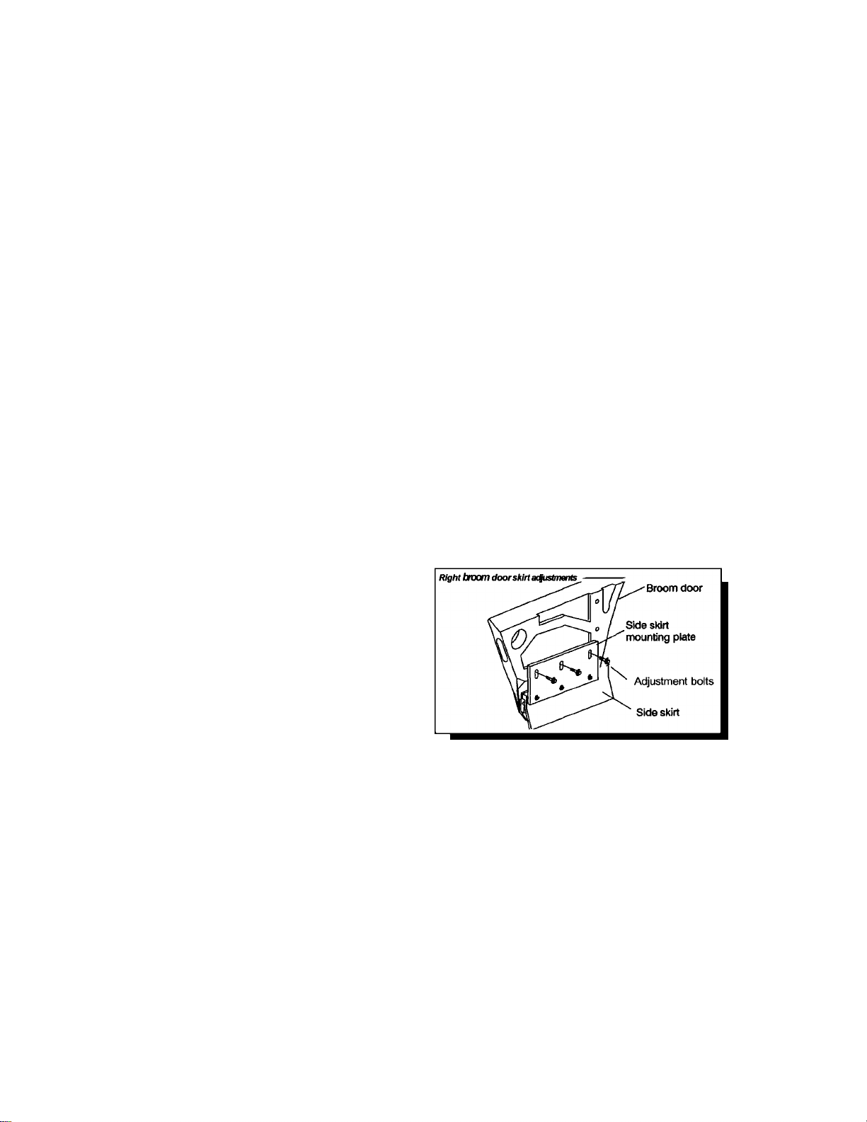
REPLACING THE RIGHT BROOM DOOR SKIRT
1. Turn off machine and set parking brake.
FOR SAFETY: Before leaving or servicing machine,
stop on level surface, apply parking brake, turn off
machine and remove key.
2. Open the right broom door.
3. Loosen the lower three retaining bolts on the
side skirt mounting plate.
4. Slide the worn side skirt out of the skirt retainer.
5. Slide a new skirt into place. Tighten the three
retaining bolts.
6. Adjust the side skirt.
ADJUSTING THE RIGHT BROOM DOOR SKIRT
1. Turn off machine and set parking brake.
FOR SAFETY: Before leaving or servicing machine,
stop on level surface, apply parking brake, turn off
machine and remove key.
2. Open the right broom door.
3. Loosen the three upper adjustment bolts on the
side skirt mounting plate.
4. Adjust the side skirt for correct floor clearance,
then tighten the three adjustment bolts.
SKIRTS AND SEALS (Refer to the Frame Group
and the Main Broom Group in the Parts section)
The main broom skirts prevent dust from exiting the
main broom chamber. The skirts should be
inspected for wear or damage daily. When correctly
adjusted, they should clear the floor by 0 to 1/8 inch
(0 to 3mm).
NOTE: Original equipment skirts are provided with
“Perform Alert™” wear indicators. The wear
indicator is raised horizontal line near the lower edge
of the skirts. When a skirt is worn to this line it
should be replaced. A skirt can be adjusted many
times before it wears to the “Perform Alert™” strip.
During daily inspections the “Perform Alert™”
indicators are useful in determining when skirts are
close to requiring replacement.
4-9
QTFSG/QTFSD 98349 05/15/03
Page 27

MAINTENANCE
REPLACING THE LEFT BROOM SKIRT
1. Turn off machine and set parking brake.
FOR SAFETY: Before leaving or servicing machine,
stop on level surface, apply parking brake, turn off
machine and remove key.
2. Raise rear cover and disconnect the batteries
from the machine.
3. Open the left broom door.
NOTE: The left skirt is mounted to the frame. This
skirt does not have a wear indicator strip.
4. Remove the five adjustment nuts and the
retaining bars.
5. Replace the worn side skirt with a new skirt.
6. Install the retaining bars and adjustment nuts.
7. Adjust the side skirt.
ADJUSTING THE LEFT BROOM SKIRT
1. Turn off machine and set parking brake.
FOR SAFETY: Before leaving or servicing machine,
stop on level surface, apply parking brake, turn off
machine and remove key.
2. Raise rear cover and disconnect the batteries
from the machine.
3. Open the left broom door.
NOTE: The left skirt is mounted to the frame. This
skirt does not have a wear indicator strip.
4. Loosen the five adjustment nuts.
5. Adjust the side skirt for correct floor clearance,
then tighten the adjustment nuts.
6. Tighten the five broom skirt.
7. Adjust the rear skirt.
ADJUSTING THE REAR BROOM SKIRT
1. Turn off machine and set parking brake.
FOR SAFETY: Before leaving or servicing machine,
stop on level surface, apply parking brake, turn off
machine and remove key.
2. Loosen the five upper adjustment nuts on the
rear skirt mounting plate.
3. Adjust the rear skirt for correct floor clearance,
then tighten the adjustment nuts.
RECIRCULATION SKIRT
The recirculation skirt helps to channel debris that
has been carried over the main broom, back into the
sweeping area. The recirculation skirt should be
checked daily for wear or damage.
REPLACING THE RECIRCULATION SKIRT
1. Turn off machine and set parking brake.
FOR SAFETY: Before leaving or servicing machine,
stop on level surface, apply parking brake, turn off
machine and remove key.
2. Raise the rear cover and disconnect the
batteries from the machine.
3. Remove the main broom.
4. Open the left broom door.
5. Remove the three retaining nuts and retaining
strip on the left side broom skirt.
6. Loosen the five retaining nuts on the
recirculating skirt retaining plate.
7. Slide the worn skirt out of the skirt retainer and
replace with a new skirt.
8. Hold the skirt firmly in place and tighten the five
retaining bolts. No adjustment is required.
QTFSG/QTFSD 98349 05/15/03
4-10
Page 28

MAINTENANCE
HOPPER SEALS
The hopper seals prevent dust from exiting around
the hopper where it meets the broom chamber.
There are two side hopper seals and one upper
hopper seal. These seals should be inspected for
wear or damage daily. When correctly adjusted, the
two hopper side seals should clear the floor by 0 to
1/8 inch (0 to 3mm).
REPLACING THE HOPPER SEALS
1. Park the machine on a smooth, level floor.
2. Raise the hopper and engage the hopper safety
arm.
Raised hopper may fall. Engage hopper safety
arm.
3. Turn off machine and set parking brake.
FOR SAFETY: Before leaving or servicing machine,
stop on level surface, apply parking brake, turn off
machine and remove key.
4. Remove the retaining bolts and retaining bar.
5. Replace the worn hopper seal with a new seal.
6. Install the retaining bar and bolts.
7. Adjust the hopper side seals.
HOPPER LIP SKIRTS
The hopper lip skirts seal the area between the lip of
the hopper and the floor. They also help deflect
debris into the hopper. The lip skirts should be
inspected for wear or damage daily. The lip skirts do
not require adjustment. They should be replaced
when the lower edge is worn down to the “Perform
Alert™” wear indicator line.
REPLACING THE HOPPER LIP SKIRTS
1. Empty the debris hopper.
2. Park the machine on a smooth, level floor.
3. Raise the hopper and engage the hopper safety
arm.
ADJUSTING THE HOPPER SIDE SEALS
1. Park the machine on a smooth, level floor.
2. Raise the hopper and engage the hopper safety
arm.
Raised hopper may fall. Engage hopper safety
arm.
3. Turn off machine and set parking brake.
FOR SAFETY: Before leaving or servicing machine,
stop on level surface, apply parking brake, turn off
machine and remove key.
4. Loosen the three adjustment bolts.
5. Adjust the hopper side seals for correct floor
clearance, then tighten the adjustment bolts.
6. Connect the batteries and lower the hopper.
Raised hopper may fall. Engage hopper safety
arm.
4. Turn off machine and set parking brake.
FOR SAFETY: Before leaving or servicing machine,
stop on level surface, apply parking brake, turn off
machine and remove key.
5. Remove the retainer plate on the right side of
the hopper.
6. Loosen the four lip skirt retaining bolts.
7. Slide the four hopper lip skirts out of the retainer
plate.
8. Slide the new hopper lip skirts into place.
9. Tighten the retaining bolts and replace lip skirt
retainer.
4-11
QTFSG/QTFSD 98349 05/15/03
Page 29

MAINTENANCE
HOPPER DOOR SEALS
The hopper door seals prevent debris from spilling
out of the hopper before dumping. There are two
hopper door side seals, one hopper door lower seal
and one hopper door upper seal. The upper seal
can only be replaced by removing the hopper door
from the hopper. The hopper door seals should be
inspected for wear or damage daily. They do not
require adjustment.
REPLACING DOOR SEALS
1. Empty the debris hopper.
2. Park the machine on a smooth, level floor.
3. Raise the hopper and engage the hopper safety
arm.
Raised hopper may fall. Engage hopper safety
arm.
4. Partially open the hopper dump door so that
both sides of the hopper door can be accessed.
5. Turn off machine and set parking brake.
FOR SAFETY: Before leaving or servicing machine,
stop on level surface, apply parking brake, turn off
machine and remove key.
6. Remove the retainer bar from the worn or
damaged seal.
7. Remove the old seal and place the new seal in
position.
NOTE: When replacing the lower door seal, a new
seal cord must be used.
8. Replace the seal retaining bar. Replace and
tighten the screws.
HOPPER
4. Check the distance from the lower rear edge of
the hopper to the floor. The correct clearance is
2 inches (51 mm). The clearance should be
equal from side to side. A good method for
checking this clearance is to slide a 2 inch
(51mm) high bar under the hopper.
5. If necessary, loosen the two rear hopper
attachment bolts, raise or lower the rear of the
hopper to obtain the correct floor clearance, and
tighten bolts.
HOPPER DUST FILTER
The hopper dust filter cleans the dust laden air that
is drawn up from the hopper by the vacuum impeller.
The filter is located above the hopper and is
accessed by raising the filter cover. The filter should
be cleaned daily by pressing the filter shaker button
for 10-20 seconds. The filter should be removed,
cleaned and inspected after every 100 hours of
operation. Replace if damaged.
TO REMOVE AND REPLACE HOPPER DUST
FILTER
1. Turn off machine and set parking brake.
FOR SAFETY: Before leaving or servicing machine,
stop on level surface, apply parking brake, turn off
machine and remove key.
2. Raise the filter cover.
3. Loosen the four filter retaining bolts.
4. Rotate the lower two filter retaining tabs down.
5. Lift the left side of the upper filter retaining bar to
clear the retaining bolt and swing the bar down
to clear the right side of the filter panel.
6. Remove the filter.
7. After inspection or cleaning, install the dust filter
with the air flow arrow pointing up.
8. Replace the filter retaining bar, and the two
lower retaining tabs. Tighten the bolts.
The hopper holds debris swept by the main broom.
The hopper should be dumped after each day of
operation and cleaned every 200 hours of operation.
For efficient sweeping, the correct hopper floor
clearance must be maintained.
1. Empty the hopper.
2. Park the machine on a smooth, level floor.
3. Turn off machine and set parking brake.
FOR SAFETY: Before leaving or servicing machine,
stop on level surface, apply parking brake, turn off
machine and remove key.
QTFSG/QTFSD 98349 05/15/03
4-12
Page 30

MAINTENANCE
To clean the filter after removal, use one of the
following methods:
1. TAPPING Tap the filter frame gently on the
dirty side of the filter down. Be
careful not to dent the filter frame.
2. AIR Blow compressed air through the
filter opposite the direction of the
arrow on the side of the filter. This
may be done with filter in the
machine. Wear eye and dust
inhalation protection when using
compressed air.
3. WATER The filter can be soaked in water
and mild detergent. Rinse the filter
until it is clean. Air dry the filter.
NOTE: Do not install the filter until it is completely
dry.
BRAKES (Refer to the Brake Group in the Parts
section)
The brake pedal and the parking brake operate the
two front tire disc brakes. The disc brakes should be
checked every 200 hours of operation, and adjusted
if necessary. The disc brakes should be adjusted so
that the disc pads are as close to the brake disc as
possible, without causing the brakes to drag.
TIRES
Tires should be inspected after every 100 hours of
operation. Pneumatic tires should be inflated to 90
PSI.
TO ADJUST THE BRAKES
1. Raise the hopper.
2. Engage the hopper safety arm.
Raised hopper arm may fall. Engage hopper
safety arm.
3. Turn off machine. Do not set parking brake.
FOR SAFETY: Before leaving or servicing machine,
stop on level surface, apply parking brake, turn off
machine and remove key.
4. Raise rear cover.
5. Disconnect batteries from machine.
6. Locate the brake adjustment screw on each
brake caliper.
7. Loosen the locknut and turn the adjusting screw
to adjust each brake. Tighten the locknut.
8. Lower the hopper.
9. Test brakes before beginning normal operations.
4-13
QTFSG/QTFSD 98349 05/15/03
Page 31

MAINTENANCE
SPECIFIC GRAVITY
BATTERY CONDITION
BATTERY
The battery provides the power to start the machine.
The battery requires regular maintenance to keep
them operating at peak efficiency.
To get the greatest life from the battery charge it
when their charge level reaches 25%of a full charge.
Use a hydrometer to check the charge level.
Do not allow the battery to remain in a discharged
condition for any length of time. Never expose a
discharged battery to temperatures below freezing.
Discharged batteries will freeze causing cracked
case. Do not operate the machine if the battery is in
poor condition or if they have a charge level below
25%, specific gravity below 1.177.
Keep all metallic objects off the top of the battery, as
they may cause a short circuit. Replace worn or
damaged cables and terminals.
Check the electrolyte level in each battery cell
before and after charging the battery. Never add
acid to the battery, use water. Do not allow water
level to fall below the battery plates. Portions of
plates exposed to air will be destroyed. Do not
overfill. Keep plugs firmly in place at all times.
The battery in this machine is rated at 12V, 550cca.
It is located under the engine, center of frame.
When removing the battery cables, remove the
negative (-) cable before removing the positive (+)
cable.
BATTERY MAINTENANCE
1. When cleaning the battery, use a solution of
baking soda and water. Do not allow the
cleaning fluid to enter the battery cells.
Electrolyte will be neutralized.
2. Maintain the proper electrolyte level in each
battery cell. If a cell should accidentally
overflow, clean immediately.
3. Do not add water until the battery is fully
charged.
4. Wipe off the top of the batteries at least once a
week.
5. Test battery condition with a hydrometer at least
once a week.
6. Ensure that all connections are tight and all
corrosion removed.
7. Every 4 to 6 months, remove the batteries from
the machine and clean the battery cases and
battery compartment.
NOTE: Do not take readings immediately after
adding water. If the water and acid are not
thoroughly mixed, the reading may not be accurate.
! WARNING
When servicing machine, avoid contact with
acid.
! WARNING
Batteries emit hydrogen gas. Explosion or fire
can result. Keep sparks and open flame away.
Keep covers open when charging.
! WARNING
Wear eye protection and protective clothing
when working with batteries.
! WARNING
Charge batteries in a well-ventilated area.
To find the correct specific gravity reading when the
temperature of the battery electrolyte is other then
80L F (27L C).
1.265 100% CHARGED
1.225 75% CHARGED
1.190 50% CHARGED
1.155 25% CHARGED
1.120 DISCHARGED
Add (+) to the specific gravity reading
0.004 (4 points), for each 10L F (6L C) above 80 L F
(27L C) Subtract (-) from the specific gravity reading
0.004 (4 points), for each 10L F (6L C) below 80L F
(27L C).
QTFSG/QTFSD 98349 05/15/03
4-14
Page 32

HYDRAULIC SCHEMATIC
HYDRAULIC TROUBLESHOOTING
PROBLEM CAUSE SOLUTION
Hopper will not lift
Hopper will not lower
4-15
Loss of power to rocker
switch
Low hydraulic fluid Add hydraulic fluid
Hopper overloaded Empty hopper
Rocker switch failure Test – replace switch
Speed control orifice
plugged
Pump solenoid failure Replace pump solenoid
Check valve failure Replace check valve or solenoid
Lift cylinder failure Replace cylinder seals
Gear pump failure Replace pump or pump motor
Loss of power to rocker
switch
Rocker switch failure Test – replace switch
Speed control orifice
plugged
Check valve failure Replace check valve or solenoid
QTFSG/QTFSD 98349 05/15/03
Key switch must be on check circuit breaker
Clean or replace orifice (located behind the lower
cylinder fitting)
Key switch must be on, check circuit breaker
Clean or replace orifice (located behind the lower
cylinder fitting)
Page 33

PROPEL SYSTEM TROUBLESHOOTING
PROBLEM. CAUSE SOLUTION
No propelling Low battery charge Charge battery.
Controller overheated Thermal switch tripped. Allow cool down period.
Loose or broken wires or
motor failure
Blown fuse (120A) Replace fuse.
Main contactor failure Replace main contactor.
Key operated on/off switch
failure
Chain failure Repair chain.
Machine moves without
pressing foot pedal
Full speed only Pedal linkage frozen Repair or adjust linkage.
Machine will not reach
full speed
Forward speed only Transmission failure Inspect, repair or replace.
Reverse speed only Transmission failure Inspect, repair or replace.
Sporadic operation Transmission failure Inspect, repair or replace.
Throttle not set at “neutral“
position
Transmission belt slipping
or linkage needs
adjustment
Located, then fix or replace wire(s). Check motor for
binding. Check motor for failure.
Replace on/off switch.
Adjust linkage.
Charge battery.
QTFSG/QTFSD 98349 05/15/03
4-16
Page 34

MACHINE TROUBLESHOOTING
PROBLEM. CAUSE SOLUTION
Excessive dusting Dust skirts and seals worn,
damaged, not adjusted
properly
Dust filter clogged or
damaged
Vacuum hose damaged Replace vacuum hose.
Vacuum fan not operated Belt loose, broken or off pulley.
Poor sweeping
performance
Machine travels slowly
or not at all
Broom bristles worn Replace brooms.
Brooms not adjusted
properly.
Debris caught in broom
drive mechanism.
Main broom drive failure Belt loose, broken or off pulley.
Side broom drive failure Check circuit breaker. Check side broom motor
Hopper dump door closed Open dump door.
Hopper full Empty hopper.
Hopper floor skirts worn,
damaged
Parking brake set Release parking brake.
Towing valve activated. Release towing valve.
Linkage broken or not
properly adjusted
Transmission drive belt
slipping or broken
Main engine drive belt
failure
Differential drive chain
failure.
Replace or adjust skirts or seals.
Shake and clean or replace filter.
Adjust brooms.
Free mechanism of debris.
circuit.
Replace skirts.
Inspect and adjust or repair.
Inspect and repair.
Inspect and repair.
Inspect and repair.
4-17
QTFSG/QTFSD 98349 05/15/03
Page 35

4-18
SERVICE SCHEDULE
MAINTENANCE DAILY WEEKLY 50HRS
Check and add fuel (see Engine’s
Owner’s Manual supplied)
Check and add engine oil (see
Engine’s Owner’s Manual supplied)
Check for fuel, oil and coolant leakage
(see Engine’s Owner’s Manual
supplied)
Check radiator for dust and insects
(see Engine’s Owner’s Manual
supplied)
Check water level of batteries after
charging
Check main broom & side broom
adjustment, remove string, etc – check
for damage
Check main broom skirts and seals *
Check hopper lip skirts for damage and
wear
Visually check tires for damage and
proper inflation
Check for leaks under hydraulic power
unit and at cylinder
Check hopper side seals for
adjustment and wear
Check hopper top seals for wear
Check air pressure in pneumatic tires
(90PSI)
Check air cleaner foam element (see
Engine’s Owner’s Manual supplied)
Rotate main broom end-for-end *
Check skirt floor clearance
Tighten wheel nuts *
Check carburetor adjustment
*
*
*
*
*
*
*
*
*
*
*
*
*
MAINTENANCE
*
*
NOTE: More frequent intervals may be required in extremely dusty conditions.
QTFSG/QTFSD 98349 05/15/03
 Loading...