

Page 1
SENSOR
S12
wRB
n
Page 2

IMPORTANT
SAFETY
INSTRUCTIONS
When using an electrical appliance, basic precautions must always be followed,
including the following.
READ
ALL
INSTRUCTIONS BEFORE USING THIS MACHINE
WARN
I
NG
5
T
O
reduce the risk of fire, electric shock, or injury:
1
;
Do
not leave appliance when plugged in. Unplug from outlet when not in use and before servicing.
2.
Do
not use outdoors or on wet surfaces.
3.
Do
not use near small children.
Do
not allow to be used as a toy. Close attention is necessary when used
by or near children.
4. Use only as described in this manual. Use only manufacturer's recommended attachments.
5.
Do
not use with damaged cord or plug. If appliance is not working as
it
should has been dropped,
6
Do
not pull or carry by cord, use cord as a handle, close a door on cord, or pull cord around sharp edges
7.
Do
not unplug by pulling on cord.
To
unplug, grasp the plug, not the cord.
8.
Do
not handle plug or appliance with wet hands.
9.
Do
not put any object into openings.
Do
not 'use with any opening blocked; keep free of dust, lint, hair,
and anything that may reduce air flow.
10. Keep hair, loose clothing, fingers, and all parts of body away from openings and moving parts.,
Do
not
place fingers or other body parts under vacuum unless unplugged.
11.
Do
not pick up anything that is burning or smoking, such as cigarettes, matches, or hot ashes.
12.
Do
not use without dust bag and/or filters in place.
13. Turn
off
all controls before unplugging.
14. Use extra care when cleaning on stairs.
15.
Do
not use to pick up flammable or combustible liquids such as gasoline or use in areas where they may
16. Machines can cause a fire when operated near flammable vapors or materials.
Do
not operate this
17. Maintenance and repairs must be done by qualified personnel.
18. Use only identical replacement parts. See instructions for Servicing
of
Appliances.
19.
Do
not use machine as a step.
20. If used on plush carpet or carpet with thick padding, do not leave machine in one place with machine
21.
Do
not use the handle in the dust bag housing cover to carry the machine.
22. Always turn
off
this appliance before connecting or disconnecting motorized nozzle.
23. Brush may unexpectedly restart.
To
reduce the risk of injury from moving parts. - Unplug before servicing.
24. The vacuum has a manual reset thermal protector. The protector is reset by switching off the vacuum.
The thermal protector needs some time to cool down after switching
off!
Check the vacum for air blockages
or mechanical failures before switching on.
25. Store the vacuum in a dry place at room temperature. When the vacuum is not in use, you should wrap the
cord on the cable hooks.
26. Any other servicing should be performed by an authorized service representative.
damaged, left outdoors, or dropped into water, return
it
to a service center.
or corners.
Do
not run appliance over cord. Keep cord away from heated surfaces.
be present.
machine near flammable fluids, dust or vapors.
turned on.
SAVE THESE INSTRUCTIONS
Page 3
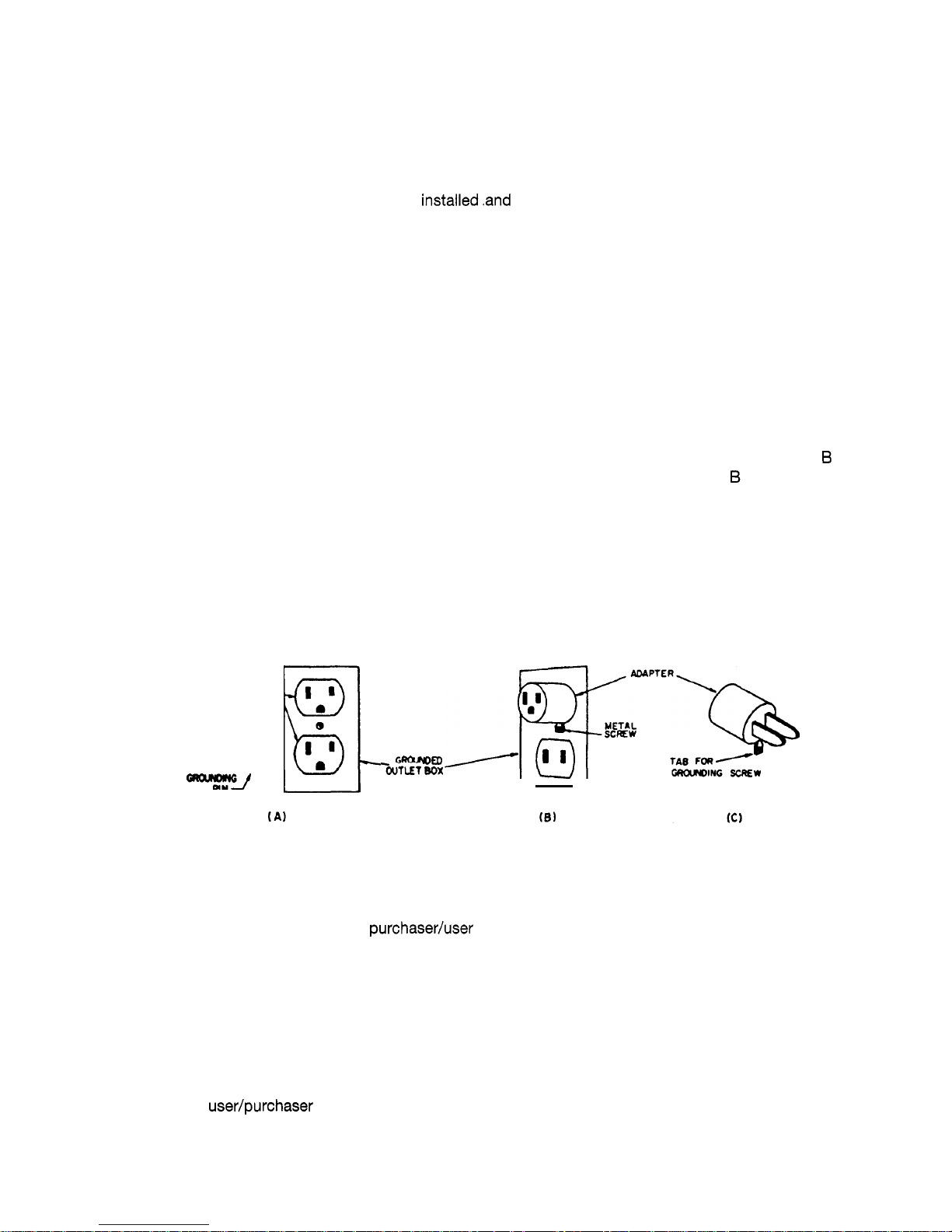
GROUNDING INSTRUCTIONS
This appliance must be grounded. If
it
should malfunction or breakdown, grounding provides a path
of least resistance, for electric current to reduce the risk of electric shock. This appliance is equipped
with a cord having an equipment
-
grounding conductor and grounding plug. The plug must be inserted
into an appropriate outlet that is properly
installed.and grounded in accordance with all local codes
and ordinances.
WARNING
Improper connection of the equipment-grounding conductor can result in a risk of electric shock.
Check with a qualified electrician or service person if you are in doubt as to whether the outlet is
properly grounded. Do not modify the plug provided with the appliance
-
if it will not fit the outlet,
have a proper outlet installed by a qualified electrician.
This appliance is for use on a nominal 120
-
volt circuit, and has a grounded plug that looks like the
plug illustrated in sketch
A. A
temporary apaptor that looks like the adaptor illustrated in sketches
6
and C may be used to connect this plug to a 2-pole receptacle as shown in sketch 6 if a properly
grounded outlet is not available. The temporary adaptor should be used only until a porperly grounded
outlet is not available. The temporary adaptor should be used only until a properly grounded outlet
(sketch
A)
can be installed by a qualified electrician. The green colored rigid ear, lug, or the like exten
ding from the adaptor must be connected to a permanent ground such as a properly
grounded outlet box cover. Whenever the adaptor is used,
it
must be held in place by a metal screw.
Note: In Canada, the use of a temporary adaptor is not permitted by the Canadian Electrical Code.
-J
AN
GROChlOED
-iWflEf
Box
LIMITED WARRANTY
WINDSOR warrants to the original purchaseduser that this product is unconditionally guaranteed free
from defects in workmanship and materials under normal use and service for a period of one year.
The vacuum motor and belts are warranted for a period of two years.
WINDSOR will, at its option, repair or replace without charge, except for transportations costs, parts
that fail under normal use and service when operated and maintained in accordance with the
Instructions Manual. This warranty does not apply to normal wear or to items whose life is dependent
on their use and care.
This warranty is in lieu of all other warranties, expressed or implied, and releases WINDSOR from all
other obligations and liabilities.
It
is applicable only in the
U.S.A.
and Canada, and is extended only to
the original
user/purchaser of this product. WINDSOR is not responsible for costs for repairs perfor
med by persons other than those specifically authorized by WINDSOR. This warranty does not apply
to damage from transportation, alterations by unauthorized persons, misuse or abuse of the equipment,
use of noncompatible chemicals, or damage or losses of income due to malfunctioning of the product.
If a difficulty develops with this product, you should contact the dealer from whom
it
was purchased.
Page 4

Accidents due to misuse can only be prevented by those using the machine.
To
guard against injury, basic safety
This vacuum cleaner is designed to be saf
electrical or mechanical parts, cleaner sh
using in order to avoid further damage to machine or physical injury to user.
A
ould e
aleckical
shock and mise this possibility obse
fol
ot r ner ove
old.
Avoid closing doors on power cord, pulling it around sharp edges, or placing sharp-edged objects
pon it.
cor
If
used on plush carpet or carpet with thick padding, turn
off
unit when handle is in upright position. When using
accessory tools, keep floor brush
off
carpet by keeping handle in locked position and lowering handle with one
hand to raise brush
off
flo
Always plug
your cleaner into a standard wall
out1
Use of extension cord ar
li
shock or fire hazard.
before Servicing, such as changin
e~
s@xdd switch ac
Operate accessories with other hand.
~
er from electric
b6 turned on. Dis
electrical outlet
bef
hing powerhead.
Do not use your vacuum cleaner in areas where flammable and/or explosi
possibility of fire
ar
explosion. Some cleanin$fluids can produce such vapors. Areas on which cleaning fluids
have been used should be c
To
avoid fire hazard,
do
not
pi
uumed.
al with cleaner.
I
Keep your work area well lighted
to
avoid picking up harmful materials (such as liquids, sharp objects, or burning
sub ide
ng the cleaner
on
i
al damage. Proper
aused by
trippi
S
tor
CI
llow children to play
Page 5

Picture
1
7
Frontcover
8
Housing release button
9
Base with brush
10
Cable
18
Pile adjustment knob
When the handle has been pushed down as
far as it will go press catch
(22)
down. If the
handle is not pushed fully down the machine
will not work.
Connecting tube
'(24),
so
that it clicks into
place.
Page 6

A Filter level indicator
B Brush controller
Filter level indicator
The red warning light (A) indicates a blockage or
a full bag,
so
check:
a)
Is
the dust bag full?
b) Is there a blockage in the hose or power
head?
If the red light is disregarded the machine will
shut
off
and the light will flash.
Brush controller
The electronic brush controller continuously
monitors the operation of the brush.
If the red light
(B)
stays
off,
the operation of the
brush is correct.
If the red light
(B)
turns on in positions
1-4
of
the Pile adjustment knob adjust the brush by
turning the Pile adjustment knob to a lower
position.
If the red light
(B)
burns continuously in the
position
1,
the brush must be changed for a
new one.
If
the machine turns
off
and the red light
(B)
flas
hes, the brush has become blocked and is not
turning. Switch the machine off, unplug it from
the mains and clear the blockage.
If there is no blockage, and machine turns
off
with brush light flashing, raise brush to a higher
position.
When the machine is switched on in the upright
position the brush automatically rises from the
carpet. To release the machine from the upright
position, press down the foot pedal
(19).
The
brush will automatically lower. The handle can be
lowered to an intermediate stop position in order
to lift up the brush head. To lower the
handle to a horizontal position, the foot pedal
must be pressed a second time. The stop positi
-
on can be closed off by a slider on the swivel
neck
(25)
so
that the handle will go from vertical
to horizontal in one movement.
To vacuum in corners etc.:
take hold of the telescopic handle grip, lift, it
away from the machine and stretch out the hose.
After use insert the telescopic attachment tube
into the back of the machine. Raise the handle of
the machine and the hose will automatically
retract. To use the hose without the tube as
shown in the right hand picture, the hose will pull
out of the tube while the tube is fitted to the
machine. Alternatively, press the release catch
(27)
on picture
2.
To vacuum under beds etc., the machine can be
fitted with an additional straight tune and the
floor nozzle. The machine will then perform as a
cylinder vacuum.
Never run over the cable with the brushlsuc-
tion head.
Always carry the machine over steps and sills.
Page 7

29
-
-
3
Maintenance
CAUTION - Always unplug machine at
mains outlet before dismantling any part
of machine.
If red light (A) shows, change paper filter bag.
To do this first pull cover release
(5)
picture
1
forward and lift the cover from the dust bag
housing. Slide the dust bag sealing plate (28)
from the holder (29). Slide the sealing plate (28)
of a new bag into the holder and push firmly in.
Insert cover into dust bag housing push is for
-
ward then lock
it
in place by pushing down the
cover release
(5).
The micro hygiene filter (30) needs to be
changed when it becomes clogged with dust
or after approximately 20 paper bags have
been used. To change the hygiene filter first
remove the cover then slide the filter out at the
bottom. To replace lift the lever and slide the
new filter in.
After 20 paper bags have been used also
change the exhaust filter (32). To remove the
exhaust filter push the catch (33) forward and
remove the filter cover (34) and filter.
Insert the new filter and replace the filter cover.
To change the brush roller (35) push the button
(36), remove the slide plate (37), turn the brush
clockwise a quarter of a turn and pull the brush
roller out. Slide the new brush roller into the
brush housing and turn it until it locates into
position. Push the button (36) and press the
side plate (37) back into place.
Underneath the machine is an inspection door
to check for blockages (38).
Blockages in the neck (20
-
picture
2)
can be
checked by first lifting
off
the dust bag housing
by pressing the catch (8). Then release the foot
pedal, lower the neck and check into the tube
next to the pedal.
Blockages in the hose can cleared by taking
the hose
off
the machine and replacing
it
the
wrong way round in the connecting tube (24)
holding it upright with one hand blocking the
top and switching on the machine.
(If necessary quickly lift your hand on and
off
the end of the hose).
The guarantee is invalidated
if
take out
parts not approved by
WINDSOR,
eg. bags,
filters, brush roller, etc., are
fmed!
Page 8

ZBK
SEmSI2
120
V
GREY
P
U
1-
23
-
/
/'
I
25
u
16
15
W
J
-3a
/
-39
50
/-49
i
c1
06747 C-09.2002
Pos.
1
2
3
4
5
6
7
8
9
10
11
12
13
14
15
16
17
18
19
20
21
22
23
24
25
26
27
28
29
30
31
32
33
34
35
36
37
38
39
40
41
42
43
44
45
46
47
48
49
50
51
Product-
No.
5625
UL
5296
EW
5359
hg
2301
1
0532
EW
5160
bl
5161
hg
5162
01
03
0846
5256
ER
01
29
51 87
01
02
5040
hg
5045
hg
5803
hg
5319
5706
bl
5324
5360
5091
5800
WI
5300
5301
ER
5380
HG
51
64
5208
5210
1073
5099
5098
hg
01
87
5145
hg
5146
5144
hg
5424
dg
5281
hg
1823
hg
5084
5255
ER
5266
5043
5289
51 63
5085
hg
5082
bl
5083
5215
UL
1491
JE
1092
JE
Description
Handle with cable, cpl.
Handle grip (incl.
Pos.
7
+
10)
Grommet
Power supply cord
Switch, cpl.
Switch cap, blue
Switch cap holder
Cable clamp
Screw C
3,9 x 16
DIN
7981
Antistatic-wire, cpl.
Handle cable
Screw,
M4 x 12
Handle tube
Screw F
3,9 x 13
DIN
7981
Hose, cpl.
Extension tube
Cover
Bag holder spring
Cover release, blue
Bag holder cpl.
(incl.
Pos.
20+21)
Safety catch
Safety catch spring
Front cover cpl.
Paper bag
Micro Hygiene Filter
Internal cover, compl.
(incl. Pos.
43 +44)
Cable clamp
Filter safety catch
Return spring
Clamp
Handle lock plate
Lock catch
Lock pin
4 x 33,5
Carrying handle
Stop spring
Cable hook
Retaining ring
Dust bag housing
Attachment clip
Spring for locking rod
Internal cable
Cable clamp
Seal
Seal
Seal
Dust bag hous. bumper base
Dust bag housing locking
Locking rod
Dust bag housing
Upholstery nozzle
Crevice nozzle
Page 9

120
V
GREY
06747 C-09.2002
POS. Product-
No.
100 2831
WI
101 2846
102 2820
BL
103 2827
UL
104 2886
105 2494
106 0102
107 2835
108 0869
109 2825
110 2824
Ill
5479
112 5717
113 2890
ER
114 0864
115
5713bl
116 5103
117 5051
hg
118 5053
119
5059dg
120 2010
121
5055
hg
122 2014
123 5813
124 5287
bl
125 2869
hg
126 2868or
127 5303
128 5304
129 2861
130 5174
hg
131 2849
132 01010
133 2860
hg
134 2833
135 2862
hg
136 2834
137 2856
138 2867
139 2821
HG
140 5411
hg
141 2829
hg
142 0197
143 5401
144 5402
145 5005
hg
146 5469
05117
S
147 5462
148 5100
149 2826
BL
150
2839
sw
151
5129
153
5112sw
154 2881
ER
155 0107
156 0143
157 5464
158 511711
159 0104
160 5463
161 5110
162 5766
hg
163 0103
164 0140
165
0176TL
152 5107-1
Description
Power head cover S
12,
cpl
Exhaust filter
Exhaust filter cover
Swivel neck assembly
Male contact holder
Cable clamp
Screw
F
3,9x13
DIN
7981
Bypass valve
Internal cable
Swivel neck bearing r.h
Swivel neck support r.h
Swivel neck support
1.h
Swivel neck bearing 1.h
PCB Power supply
Internal cable
Brush roller release
Spring
Axle assembly
Axle
Foot pedal
Axle spring
Wheel, cpl.
Axle clamp
Brush roller
Bearing block right hand
Rubbing plate
Access door
(incl. Pos.
127 + 128)
Access door axle
Access door spring
Pile adjustment axle
Pile adjustment wheel
Axle clamp
Screw
AM4
x 16,
DIN
7985
Cover
Thrust member
Pile adjustment knob
Thrust member
Clamp
Spring
Chassis
S12,
cpl.
Front bottom plate, cpl
Rear bottom plate, cpl
(incl. Pos.
142)
Srew
M4x12
Wire tie
Wire tie
Bumper, set
Motor
1
OOOW
I
120V
Carbon brush set
Motor pulley
2MR
Rubber mounting
Motor cover
Cover for air channel
Support lever
Support spring
Motor pulley cover
Computer controller
Screw C
2,9 x 13
Washer
3,2
DIN
125
Sensor
X4
cpl.
Motor pulley
Screw C
3,9x25
DIN
7981
Belt
2MR-310-6
Belt
219 3M
HTDII-6
Bearing block
1.h cpl.
Screw C
3,9x 16
DIN
7981
Washer
4,3
Screw
AM4x30
DIN
7985
TL
Page 10

IB
I
2~
1
U
I
C
2
1
A Attachments
1
Upholstery Nozzle
2
Crevice Nozzle
B
Optional Attachments
1
Extension Hose
2
Straight Tube
3
Dusting Brush
4
Upholstery Nozzle, special
5
Wall- and Floor Brush
C Service Parts
1
Paper Bag
2
Micro-Hygiene-Filter
3
Exhaust Filter
3
Brush Roller
WARNING
!
Electric shock could occur
A
if
used outdoors or
on
wet surfaces
I
Technical Details
Vacuum motor..
.........
Water lift
...............
Air
flow
................
Dust
bag capacity.
.......
Working width
...........
Brush drive
.............
Brush speed
............
Floor adjustment.
........
Cable
.................
Weight
.................
Radio supression.
........
1200
Watt
2300
mm
(90”)
50
US
(105
CFM)
5,3
liters
308
mm
(1
2’3
tooth belt
2700
rpm
automatically sensor
advised
12’2
m
(40
ft)
7’4
kg
(162
Ibs)
EN
5501 4 Verf.
242/91
Wiring diagram
.c
mvr
P
PP
dm
WINDSOR”
INDUSTRIES,
INC.
1351
West Stanford
Ave.
Englewood, Colorado
801 10
USA
800-444-7654
303
-
762-1 800
FAX:
303-762-081 7
06747
-
09.200:
 Loading...