

Page 1

V
MODEL: QK32
QQK32
Operating Instructions (ENG)
Mode d’emploi (FR)
Bedienungsanweisung (GER)
Lire attentivement le mode d’emploi avant la mise en service de la machine.
V
IPX4
Read instructions before operating the machine.
Vor Inbetriebnahme der Maschine Bedienungsanweisung lesen.
QUICK 98560 09/14/01
Page 2

OPERATIONS
Machine Data Log........................................2
Table of Contents.........................................1-1
Safety...........................................................2-1
Safety Label Locations.................................2-2
Technical Specifications...............................3-1
Preparing for Operations..............................3-2
Controls........................................................3-3
Machine Operation.......................................3-8
Pre-run Inspection.................................3-8
Starting Machine...................................3-8
Emergency Stop Procedure...................3-8
Filling Machine......................................3-8
Scrubbing Operation..............................3-9
Emptying and Cleaning Tanks ............ 3-10
Machine Transport and Storage................3-11
Towing or Pushing.............................. 3-11
Tie-Downs.......................................... 3-11
Jacking............................................... 3-12
Machine Storage................................3-12
MAINTENANCE
General..................................................... 4-1
Directional Control Systems...................... 4-1
Scrub Head............................................... 4-1
Scrub Brushes.....................................4-2
Scrub Deck Removal........................... 4-3
Scrub Deck Skirt and Side Squeegee..4-3
Squeegee.................................................. 4-3
Squeegee Blades..................................4-4
Replacing/Rotate...................................4-4
Remove Squeegee Tool........................4-4
Adjusting Squeegee.............................. 4-5
Drive Chain ...............................................4-6
Brakes....................................................... 4-6
Tires and Wheels...................................... 4-6
Vacuum Motor...........................................4-6
Batteries.................................................... 4-7
To Charge Batteries...............................4-8
To Install Batteries.................................. 4-8
To Remove Batteries..............................4-9
Fuse Link ..................................................4-9
Service Schedule...................................... 4-10
Machine Troubleshooting..........................4-11
Propelling System Troubleshooting........... 4-12
User Stocking List.....................................4-13
Electrical Schematic..................................4-14
TABLE OF CONTENTS
PARTS LIST
Battery Group...........................................5-1
Brake Group.............................................5-3
Circuit Breaker Group............................... 5-5
Electrical Components Group...................5-7
Floor Group.............................................. 5-9
Front Wheel Group................................... 5-11
Pedal Group .............................................5-13
Rear Wheel Group.................................... 5-15
Safety Switch Group................................. 5-17
Recovery Tank Group...............................5-19
Scrub Brush/Pad Driver Group................. 5-21
Scrub Head Group.................................... 5-23
Side Squeegee Group.............................. 5-25
Scrub Head Lift Group.............................. 5-27
Seat Group...............................................5-29
Solution Tank Group................................. 5-31
Solution Control Group.............................5-33
Squeegee Group......................................5-35
Squeegee Lift Group.................................5-37
Decal Group............................................. 5-39
Touch Pad Group.....................................5-41
Vacuum Group .........................................5-43
Steering Group.........................................5-45
Wiring Group............................................ 5-47
Front Harness...........................................5-51
Drive Motor/Touch Pad Harness............... 5-53
Rear Main Harness................................... 5-55
Touch Pad Harness/Touch Pad................ 5-57
Warranty................................................... 5-59
QUICK 98560 09/29/00
1-1
Page 3

SAFETY
The following symbols are used throughout this
guide as indicated in their descr ipt ions:
HAZARD INTENSITY LEVEL
There are three levels of hazard intensity identified
by signal words-WARNING and CAUTION and FOR
SAFETY. The level of hazard intensity is determined
by the following definitions:
! WARNING
WARNING - Hazards or unsafe practices which
COULD result in severe personal injury or death.
! CAUTION
CAUTION - Hazards or unsafe practices which could
result in minor personal injury or product or property
damage.
FOR SAFETY: To Identify actions which must be
followed for safe operation of equipment.
Report machine damage or faulty operation
immediately. Do not use the machine if it is not in
proper operating condition. Following is information
that signals some potentially dangerous conditions
to the operator or the equipment. Read this
information carefully. Know when these conditions
can exist. Locate all safety devices on the machine.
Please take the necessary steps to train the
machine operating pers onne l.
FOR SAFETY:
DO NOT OPERATE MACHINE:
• Unless Trained and Authorized.
• Unless Operation Guide is Read and
understood.
• In Flammable or Explosive areas.
• In areas with possible falling objects.
• Before use all covers and doors shall be put in
the positions specified on the instructions.
WHEN USING MACHINE:
• Use caution when backing when backing
machine.
• Do nut carry riders on the machine.
• During operation attention shall be paid to other
persons, especially children.
• Always follow basic safety an d traffic rules.
• Go slow on slippery surfaces and grades.
• When leaving unattended, secure against
unintentional movement.
WHEN SERVICING MACHINE:
• Avoid moving parts. Do not wear loose clothing;
jackets, shirts, or sleeves when working on the
machine.
• Block machine tires before jacking machine up.
• Use hoist or jack of adequate capacity to lift
machine.
• Disconnect battery connections bef or e work ing
on machine.
• Avoid contact with battery acid.
• Use Windsor supplied replacement parts.
! CAUTION
This machine is not suitable for picking up
health endangering or hazardous dust.
! WARNING
This appliance has been designed for use with
the brushes specified by the manufacturer. The
fitting of other brushes may affect its safety.
! WARNING
Batteries emit hydrogen gas. Explosion or fire
can result. Keep sparks and open flame away.
Keep covers open when charging.
! WARNING
Flammable materials or reactive metals can
cause explosion or fire. Do not pick up these
materials.
! WARNING
Hazardous voltage. Shock can result.
Disconnect batteries before working on machine.
Only qualified personnel should work inside
machine.
! WARNING
Machine can emit excessive noise. Consult with
your regulatory agency for exposure limits.
Hearing loss can result. Wear hearing
protection.
! CAUTION
This machine is not approved for use on public
paths or roads.
BEFORE LEAVING OR SERVICING MACHINE:
• Stop on a level surface.
• Set the parking brake.
• Turn off the machine.
• Remove key from switch.
2-1
QUICK 98560 09/20/99
Page 4

SAFETY LABEL LOCATION
NOTE: These drawing indicate the location of safety labels on the floor scrubber. If at any time, the labels
become illegible contact your Windsor representative for prompt replacement.
TOP VIEW WITH COVER OPEN
CAUTION
Explosive Gas Is Given Off
By Batteries During Charge.
1. Keep Battery Compartment
Cover Open.
2. No Smoking, Flame Or
Sparks In Area.
3. Charge Only In Well
Ventilated Area.
BATTERY CAUTION 80885
MANUAL DECAL 50776
FOR SAFETY
1. Do Not Operate Machine:
-Unless Trained And Authorized.
-Unless Operation Manual Is Read.
And Understood.
-In Flammable Or Explosive Areas.
-In Poorly Ventilated Areas.
2. Do Not Raise Hopper:
-Unless Machine Is On A Level
Surface.
-Unless Main And Side Brooms
Are Turned Off.
3. Do Not Use Flammable Cleaning
Agents.
4. Check For Fuel Leaks
5. Go Slow On Grades And Slippery
Surfaces.
6. Before Leaving Machine:
-Stop On Level Surface.
-Turn Off Key And Set Parking
Brake.
-When Parking Remove Key.
7. Use Quadra Company Supplied Or
Equivalent Replacement Parts.
SAFETY DECAL 80814
PARKING BRAKE
DECAL 82802
SAFETY DECAL 81505
WARNING
Flammable
Materials Can
Cause Explosion
Or Fire.
Do Not Pick Up
Flammable
Materials.
SAFETY DECAL 81494
WARNING
Flammable
Materials Can
Cause Explosion
Or Fire.
Do Not Use
Flammable
Materials In Ta n k.
QUICK 98560 09/20/99
2-2
Page 5

TECHNICAL SPECIFICATIONS
ITEM DIMENSION/CAPACITY
Normal Power 2.8 kW
Rated Voltage 24 VDC
Rated Amperage 115 amps
Batteries 4 x 6 volt 250-250 A/H
Scrub Brush Motors 2 x .75 hp (0.56 kW)
Vacuum Motors 1 x .75 hp (0.56 kW) Standard, second motor optional
Propelling Motor .75 hp (0.56 kW)
Mass (GVW) 1780 lbs. (810 kg)
Weight empty without batteries 810 (302 kg)
Solution Control Gravity feed, fully variable with automatic shut off in neutral.
Solution tank capacity 30 gal. (113.5 liter)
Recovery tank capacity 30 gal. (113.5 liter)
Scrub brush 2 dia. X 16 in. (5 cm x 40.5 cm)
Scrub brush pressure 0-150 lbs. (0-68 kg) 4 automatic pressure settings
Scrub brush speed 200 rpm
Tires (QK32)
(QQK32)
Foundation Pressure (at recommended tire psi) 35 lbs/in.²
Maximum Speed 3.7 miles/hour (5.95 km/hour)
Coverage 46,200 ft² /hour @ 3.5 mph with 2 in. overlap
Frame construction Welded cold rolled steel and steel plated
Brakes Self centering mechanical 8 in. (20.3 cm) disc with hand lock
Minimum aisle u-turn width 66 in (168 cm)
Steering Rack and Pinon
Ramp climbing 7.5 degrees
Height 53 in. (135 cm)
Length 61 in.(155 cm) without counterweighed bumper
Length 64 in. (163 cm) with counterweighted bumper
Width without squeegee 37.75 (96 cm)
Width with squeegee 41 in (104 cm)
Width of scrub path 32 in. (81 cm)
12 in. (30.5 cm) pneumatic non-marking standard
12 in. (30.5 cm) Black Knobby Foam Fill
parking brake.
LENGTH
The sound pressure level at the operators ear
was measured to be 73 dBA. This was a
nearfield, broad-band measurement taken in a
typical commercial environment on a tile floor .
This appliance contains no possible source of
impact noise. The instantaneous sound
pressure level is below 63 Pa.
3-1
HEIGHT
WIDTH
The weighted root mean square acceleration at
the operator’s arms was measured to be below
2.5 m/s² . This was a tri-axial, third-octive band
measurement made during normal operation on
a composite tile floor. The measurement and
related calculations were made in accordance
with ANSI S3.34-1986.
QUICK 98560 03/17/01
Page 6

PREPARING FOR OPERATION
The machine has been delivered to you by your
dealer serviced and ready for operation. Should any
discrepancies exist contact your dealer immediately.
BEFORE OPERATING THE QUICK©
1. Before operating check the machine for any
shipping damage. Report any damage to your
dealer.
2. Complete the machine data sheet on page 2.
3. Read this manual carefully before operating or
servicing the machine.
! CAUTION
Do not operate machine unless operation manual is
read and understood.
! CAUTION
Wear safety glasses when servicing the
batteries. Avoid contact with battery acid.
4. Check the electrolyte level of the batteries. See
“Batteries” in the Maintenance section.
5. Check the specific gravity of the batteries to
determine the charge for the batteries. See
“Batteries” in the Maintenance section.
6. Check for proper connection of the
batteries/battery to machine.
7. Check squeegee wheels for free movement.
8. Check the squeegee for proper adjustment.
9. Check for proper brush installation.
10. Check the scrub head side squeegee for proper
installation and adjustment.
11. Check tires for damage and proper inflation.
QUICK 98560 09/20/99
3-2
Page 7

CONTROLS
Q
X
K
S
R
P
F
G
A
A. Key Operated Switch
B. Directional Control Pedal
C. Brake Pedal
D. Parking Brake
E. Comfort Zone Operators Seat
F. Brush Motor/Lift Switch
G. Squeegee/Vacuum Motor Switch
H. Solution Control
I. Emergency Stop Button
J. Hour Meter
K. Battery Condition Indicator
L. Steering Wheel
M
CONTROL PANEL QUICK
M. Horn Button
N. Circuit Breakers
O. Fuses
P. Bru sh Pre ssu r e Swit ch
Q. Optional Pump Switch
R. Brush Circuit Breaker Monitor
S. Full Recovery Tank Indicator
T. Solution Tank Cover
U. Recovery Tank Drain Hose
V. Lid
W. Solution Tank Drain Hose
X. Recycle Option Switch
3-3
QUICK 98560 09/20/99
Page 8

CONTROLS
T
Q
R
O
X
H
N
B
L
V
E
W
I
D
J
U
C
QUICK 98560 09/20/99
3-4
Page 9

CONTROLS
A. KEY OPERATED SWITCH
The key switch controls the power for machine
functions. All touch panel switches are controlled by
the key switch. To operate the machine, turn the
key clockwise. To turn off the machine, turn the key
counter-clockwise. Turning off the key switch will
immediately stop the brushes, vac u um motors,
optional recycle pump, and also stop the actuators
for the deck and squeegee.
NOTE: Turning the key switch off during normal
running operation will stop all motors and actuators.
When the key is turned back on the system will
assume they are in the normal parked mode (s cr ub
deck up, squeegee up, and motors off). Any touch
panel command will send the selected system to the
working position regardless of the position it was in
when the key switch was turned off. This is normal
and will not damage machine.
FOR SAFETY: Always remove the key when
machine is unattended or during service to
prevent unauthorized movement.
B. DIRECTIONAL CONTROL PEDAL
This pedal controls the direction of travel and the
speed of the vehicle.
D. PARKING BRAKE
The parking brake lever is located on the left side of
the steering pedestal. With the service brakes fully
applied pulling the lever toward the operator then
releasing the brake pedal sets the parking brake. To
release the parking brake simply tap the brake
pedal.
FOR SAFETY: Always park on a level surface,
turn the machine off, and set the parking brake
before leaving the machine of before servicing
the machine.
E. COMFORT ZONE OPERATOR SEAT
F. BRUSH MOTOR/LIFT SWITCH
One touch on the control panel “brush” switch
automatically lowers the scrub head to the “light
Scrub” position, turns on both brush drive motors,
turns on the vacuum motor, and lowers the
squeegee. Three sets of LED’s will light on the
touch panel. The first, indicates the brush pressure
setting. The second, shows that the brush motors is
lowering. The third lights to show the vacuum motor
has been activated as well as the squeegee.
Touching the switch again turns off the brushes and
returns the scrub deck to the up position. The two
LED indicators are turned off. Also the squeegee
will raise after a delay of 15 seconds and in an
additional 15 seconds the vacuum motor will turn off.
If the scrub deck is lowered without brushes installed
the brush motors will stop, the deck will raise and all
four of the brush pressure LED’s will flash
continuously until the brush s witc h has been
pressed once again.
Slowly pressing the front of the pedal causes the
machine to travel forward. Pressing the rear of the
pedal causes the vehicle to travel in reverse. The
vehicle speed can be controlled by varying the
pressure on the front of the pedal.
FOR SAFETY: the vehicle can coast for a short
distance after releasing the directional pedal.
Remove food from pedal and use brakes to slow
or stop the machine.
C. BRAKE PEDAL
The brake pedal is located on the floor to the left
side of the steering column. This pedal operates the
disc brake on the two front wheels. To slow or stop
the vehicle, apply pressure to the brake pedal.
3-5
QUICK 98560 09/20/99
G. SQUEEGEE/VACUUM MOTOR SWITCH
A touch panel switch (with LED indicator) lowers the
squeegee and turns on the vacuum motors. This
switch will also shut off the vacuum motor/motors
and raise the squeegee if double scrubbing is
required. The LED will light when the squeegee is in
the down position. Pressing the switch again raises
the squeegee fully and turns off the vacuum motors
after approximately 15 seconds.
H. SOLUTION CONTROL
The slide lever mounted to the electric panel
controls the solution flow to the scrub deck. Pushing
the lever toward the down position allows full flow to
the floor. Pulling the lever to the up position
gradually reduces flow to full off. If the brush motors
are turned off a secondary valve automatically
interrupts the flow until the motors are turned on
again. This feature aides in preventing an
unintentional draining of the solution tank and allow
the operator to adjust the amount of solution to the
floor without resetting each time the scrubbing
operation is interrupted.
Page 10

I. EMERGENCY STOP BUTTON
The emergency stop switch controls all battery power
to the machine. In an emergency that requires quick
disconnection of the batteries, push down firmly on
the red knob.
NOTE: The emergency disconnect should only be
used for emergencies and service. Repeated nonessential use well shorten the life of the connector.
Also, when all power is removed from the machine
the battery condition meter resets to a less than
accurate full charge position when power to restored.
CONTROLS
L. STEERING WHEEL
The steering wheel turns the front wheels of the
machine causing the machine to turn.
M. HORN BUTTON
The horn button is located at the bottom of the touch
panel. The horn is activated by pressing the horn
button.
J. HOUR METER
The hour meter located at the rear of the touch panel
records the number of hours the machine has been in
operation with the scrub brushes running. This
information is useful in determining when to service
the machine
K. BATTERY CONDITION INDICATOR
The battery condition 6 LED’s indicated the present
charge of the battery. When only the LED near the
left side of the gauge is on, the batteries should be
recharged. Further operation of the machine could
damage the machine or batteries. The LED second
from left indicates 80% discharge signaling ideal time
to recharge batteries. The remaining 4 LED’s
indicate the approxim ate charge le ve l of the batteries .
When the machine is left overnight with less than a
full charge, the display may initially indicate a full
charge. It will also indicate a full charge if the
batteries are disconnected, than reconnected. After
a few minutes of operation the gauge will give the
correct charge level.
NOTE: See “Batteries” in maintenance section for
more information on battery maintenance.
N. CIRCUIT BREAKERS
The circuit breakers are circuit protection devices
designed to interrupt the flow of current in the event
of an electrical overload. When tripped, the circuit
breaker must be reset by pressing the exposed
button on the face of the affected circuit breaker. All
circuit breakers are located on the right side of the
electrical panel. If the circuit breaker continues to
trip, the cause of the electrical overload should be
found and corrected.
The following chart shows the circuit breakers and
fuses with the components they protect:
DEVICE RATINGCOMPONENT
1 Circuit
breaker
2 Circuit
breaker
3 Circuit
breaker
4 Circuit
Breaker
6 Circuit
breaker
7 Circuit
breaker
8 Circuit
breaker
Fuse 8a Touch pad Right of
Fuse 200 Drive System Electrical panel
PROTECTED
25 Rear vacuum motor Right of
25 Optional front vacuum
motor
35 Left side scrub brush Right of
35 Right side scrub brush Right of
5 Squeegee actuator Right of
5 Brush actuator Right of
10 Ignition, horn, battery
and hour meter
LOCATION
steering column
Right of
steering column
steering column
steering column
steering column
steering column
Right of
steering column
steering column
QUICK 98560 09/20/99
3-6
Page 11

CONTROLS
O. FUSE
The fuses are a one-time circuit protection device
designed to stop the flow of electrical current in the
event of an electrical overload. If a fuse is blown, it
must be replace. The knife fuse located in the
electrical panel housing protects the drive system.
The touch pad is protected by a fuse on the circuit
breaker panel.
P. BRUSH PRES SUR E SW ITCH
The brush pressure switch selects the down pressure
on the scrub deck. One touch sets the brush
pressure to light scrub. Each succeeding touch
increases the pressure one step. After four touches
the pressure returns to the lightest position to begin
the cycle again. LED’s corresponding to the pressure
position are activated on the panel above the switch.
If the scrub deck is lowered without brushes installed
the brush motors will stop, the deck will raise and all
four of the LED’s will flash continuously until the
brush switch has been pressed once again.
Q. OPTION PUMP SWITCH
Activating this switch turns on the options pump to
operate a scrub wand.
R. BRUSH CIRCUIT BREAKER MONITOR
The LED will light when either of the two brush motor
circuit breakers has tripped.
S. FULL RECOVERY TANK INDICATOR
This LED will light when th float senses a full
recovery tank. The LED will light intermittently
When the tank approaches full. When the LED is on
constantly for 70 seconds, the squeegee will raise
and the vacuum motors will turn off. The vacuum
motor cannot be activated until the recovery tank is
emptied. However the squeegee lift mechanism will
continue to function.
T. SOLUTION TANK COVER
Located on top of solution tank. Remove to fill
solution tank.
U. RECOVERY TANK DRAIN HOSE
Located at left rear of machine. Secured by clip and
closed by expandable plug.
V. RECOVERY TANK LID
Rectangular cover located on top, right side lower
tank. Cover secured by knobs.
W. SOLUTION TANK DRAIN HOSE
Locate at left rear of machine. Secured by clip and
closed by expandable plug.
X. RECYCLE OPTION SWITCH
3-7
QUICK 98560 09/20/99
Page 12

MACHINE OPERATION
PRE-RUN MACHINE INSPECTION
Do a pre-run inspection to find problems that could
cause poor performance or lost time from breakdown.
Follow the same procedure each time to avoid
missing steps.
NOTE: See maintenance section for pre-run machine
inspection checklist items.
STARTING MACHINE
NOTE: Perform pre-run machine insp ec tio n before
operating machine.
FOR SAFETY: Before starting machine, make
sure that all safety devices are in place and
operating properly.
1. The operator should be in the seat with the left
foot on the brake pedal or with the parking brake
on. The directional pedal must be in the neutral
position to avoid unintentional movement. There
is a built in safety to disable the drive system if
the key is turned on with the directional pedal
engaged. The directional pedal must go back to
neutral before the machine will move.
NOTE: The operator must be in position on the seat
in order to activate any machine functions.
2. Turn the key switch clockwise to the “ON”
position.
3. Release the brake, then press lightly on the
directional pedal in the desired direction and
drive to the filling area.
EMERGENCY STOP PROCEDURE
1. Turn key to off position. If an electrical problem
is suspected push in emergency stop button to
remove all power from machine.
2. Release pressure on direction al ped al.
3. Apply brakes.
NOTE: Turning the key switch off during normal
running operation will stop all motors and lift
actuators. When the key is turned back on the
systems will assume they are in the normal parked
mode (scrub deck up, squeegee up, and motors off).
Any switch command will send the selected system
to the working position regardless of the position it
was in when the key switch was turned off. Two
touches of the respective switch are required to raise
the scrub deck and squeegee and turn off motors.
This is normal. No damage to the machine will result.
FILLING THE QUICK©
FOR SAFETY: Before leaving or servicing
machine; stop on level surface, set parking brake,
turn off machine and remove key.
1. Set squeegee and scrub deck to up position, set
parking brake, and turn off key switch.
2. Remove solution tank cover.
Flammable materials can
! WARNING
Do not use flammable materials in the tanks.
3. Fill the solution tank with clean water, 5” from the
bottom of the fill inlet. At this level the solution
tank contains 25 gallons (97.5 liters). The water
must not be hotter than 140ºF (60ºC) to prevent
damage to the tank.
4. Measure the required amount of chemical into
the solution tank. Liquid chemicals should be
added to the solution tank after filling with water.
Dry chemicals should be thoroughly mixed before
being added into solution tank. Commercially
available, high alkaline cleaners, specifically
manufactured for floor cleaning are suitable for
use in the QUICK© solution system.
NOTE: Read the chemical manufacturers
recommended proportions instructions and
application instructions.
5. Inspect solution tank cover vent for obstructions.
A blocked vent will prevent proper flow of solution
form reaching the scrub deck.
6. Replace solution tank cover.
cause an explosion or fire.
QUICK 98560 09/20/99
3-8
Page 13

MACHINE OPERATION
SCRUBBING WITH THE QUICK©
Plan the scrubbing pattern in advance. The longest
track is around the perimeter of the area to be
cleaned. For efficient operation, the runs should be
the longest possible without turning, stopping, or
raising and lowering scrub deck/squeegee. Overlap
the bush paths and avoid transporting over
previously cleaned areas.
The QUICK© will automatically raise the squeegee
slightly when reverse travel is selected. If the
machine is allowed to stand in neutral with the scrub
head down for more than 2 seconds, brush motors
stop, solution flow stops, and the scrub deck will
raise slightly. If either forward or reverse travel is
selected, the scrub head will lower to the preset
position and solution flow will continue in the same
settings once movement begins.
NOTE: In order to achieve the best possible results,
the area which is to be cleaned should be swept
before scrubbing. Large debris, strings, wire must
be removed to prevent being caught in brushes or
squeegee.
TO BEGIN SCRUBBING
The QUICK© uses a one touch system for turning
on the brushes and vacuum motor and lowering both
to the operating position.
! CAUTION
When operating the machine around people, pay
close attention for unexpected movement. Use
extra caution around children.
! WARNING
Flammable liquids and/or reactive metals can
cause explosions or fire! Do not pick up.
1. Place left foot on brake pedal or make sure
parking brake has been set.
2. With directional pedal in neutral turn key switch
to “ON”.
3. Release brake.
4. Press directional pedal to travel in the desired
direction and steer to the start of the scrub
pattern.
5. Press the brush switch (#1) on the console
touch pad. The vacuum motors will switch on,
the LED will light, and the squeegee will lower to
the floor. The brush motors will start, the scrub
deck will lower to the light scrub position, and
the solution will begin. Three set of LED’s (one
set of four lights indicating amount of brush
pressure, one light for brush motor on, and one
light for vacuum motor on/squeegee down will all
light. The brush light will blink until the selected
pressure is attained.
NOTE: Shut machine off immediately if water or
foam is expelled from the machine.
6. To double scrub touch the squeegee switch and
the squeegee will raise.
7. Adjust the brush pressure by touching switch on
the touch pad.
8. Adjust the solution valve with lever . Solut io n wi ll
not flow to the floor until the scrub deck is
activated.
9. Adjust ground speed and solution flow to suit
cleaning conditions.
NOTE: Once solution flow rate is set it is not
necessary to shut off solution when stopping
scrubbing. Solution flow is automatically shut off
when brush motors stop. When bush motors are
turned on, flow automatically res umes.
3-9
QUICK 98560 09/20/99
Page 14

MACHINE OPERATION
TO STOP SCRUBBING
1. Press the brush motor switch (#1) on the console
touch pad. The motors will stop and the scrub
deck will raise to the park position. Nothing
further needs to be done. After 15 seconds the
squeegee will lift and the vacuum motor will run
an additional 15 seconds. These delays are
programmed to avoid leaving water between the
location the brush lifted and the sque ege e lifted,
and to clean the recovery hose.
2. Apply brake to stop machine.
3. Turn key switch off.
4. Set parking brake.
DOUBLE SCRUB
Floors which are heavily soiled or have thick
accumulations of floor finish may not clean
sufficiently with one pass. In these cases it will be
necessary to double scrub.
To double scrub, make the first pass over the surface
being cleaned with the squeegee up, the solution on,
and brushes down. This allows the solution to stay in
contact with the soil while loosening the sur f ac e
accumulation with the brushes. Allow time for the
first application to stay in contact with the floor.
Length of time between the first and second pass
depends on amount of accumulation and type of
chemical being used. A second scrubbing with the
squeegee down again the solution and brushes on
will further loosen the soil. The additional application
of solution will further assist the difficult cleaning job.
If desired the side squeegee may be locked in the up
position by raising squeegee and rotating latch.
EMPTYING AND CLEANING TANKS
RECOVERY TANK
1. Pull the solution lever all the way up to stop
solution flow if scrubbing is complete. Otherwise
raising the scrub deck will stop solution flow.
2. Touch the scrub brush switch to raise the scrub
deck, stop the brush motors, raise the squeegee
and stop the vacuum.
3. Park the QUICK© next to a floor drain.
4. Turn off the key switch and set the machine
parking brakes.
5. Unhook the drain hose from retainer. Unscrew Thandle on plug enough to loosen plug and lower
hose in direction of drain. Stand behind end of
hose. Recovered solution will come out with
force. Slowly remove plug from drain hose.
6. Recovery tank should be flushed out with clean
water on a daily basis. Do not use water hotter
than 140°F (60°C) to clean tank. Damage to tank
may occur.
7. Clean around float shut off device and check for
free movement of float.
8. Large debris or compacted dirt may be removed
by clean out cap located on left side at rear.
9. Replace plug and secure drain hose in bracket.
10. If machine is to be stored, leave recovery tank
cover open and drain cap off.
SOLUTION TANK
1. Drain solution tank by lowering clear vinyl tube
from hanging bracket. Unscrew T-handle and
remove plug.
2. Flush tank of all chemical solution.
3. Run several gallons of clean water through
system.
NOTE: Never allow solution to remain in tank.
Damage to tank, seals and valves could occur.
QUICK 98560 09/22/99
3-10
Page 15
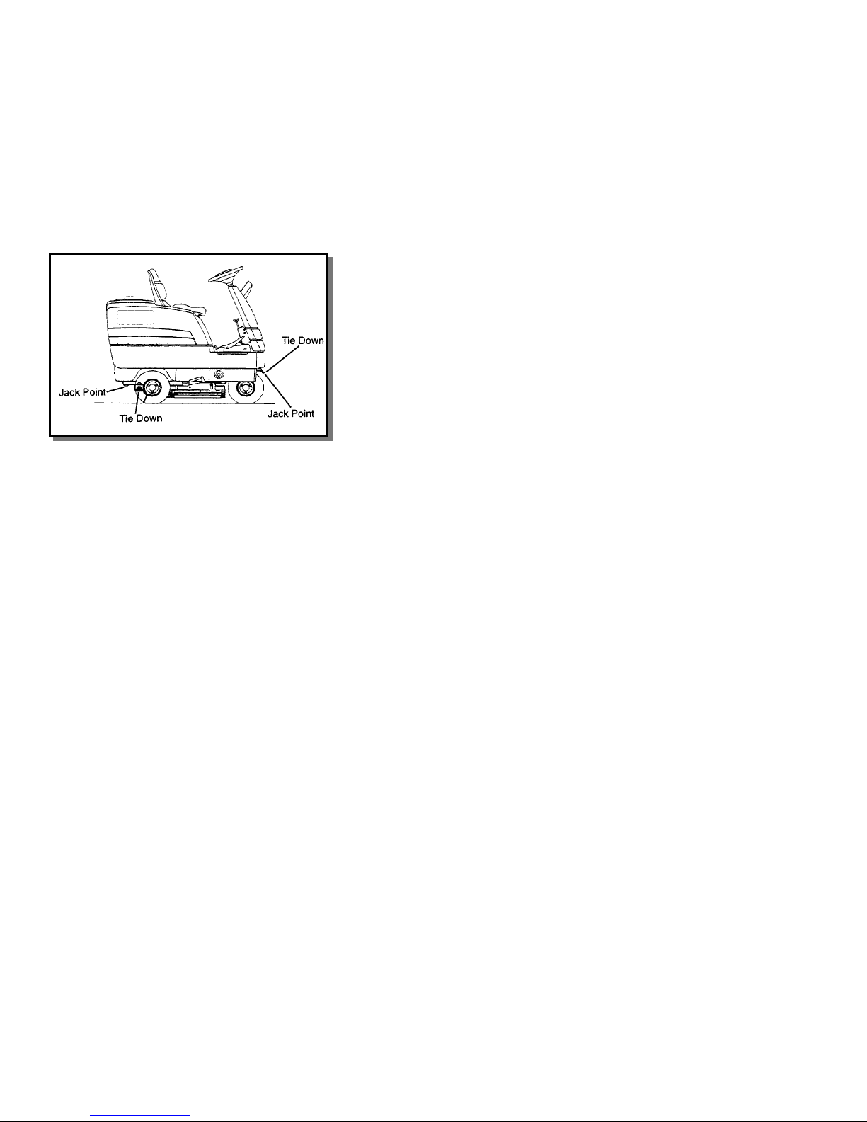
TRANSPORTING MACHINE
TOWING OR PUSHING MACHINE
The QUICK© may be towed for short distances at
speeds not to exceed 5 mph. Be careful to avoid
damaging machine. Attach towing device at tie
down point. The machine may be pushed by hand
from the rear.
NOTE: To avoid damage caused by regenerative
voltage, unplug traction motor before towing or
pushing machine.
MACHINE TIE-DOWNS
There are two tie points located at the rear, side of
the machine frame and one on the steering fork
above front tires. Tie-down devices must be of the
proper type and strength. The combined strength of
all tie-downs must be strong enough to lift tow times
the weight of the machine. Tie-downs must be
positioned to prevent the machine from moving
forward, backward, or either side to side. Use all
four corners of the machine with the tie-downs
running out opposite directions . Tie- d o wns m ust be
attached to the transporting vehicle securely.
PREPARATION FOR TRANSPORTING
Remove squeegee tool to eliminate interference with
tie-downs.
Scrub head must be in the up position before
loading.
NOTE: When transporting the machine on a trailer or
in a truck, in addition to using tie-downs, be sure to
set the parking brake, and block the tires to prevent
the machine from rolling.
MACHINE JACKING
The machine may be jacked up for service or
inspection by using the specified jack locations.
Always block the tires when jacking up the machine.
FOR SAFETY: Before leaving or servicing
machine; Stop on level surface, set parking
brake, turn off machine and remove key.
The rear jack points are the frame just behind the
rear wheels. Remove the squeegee tool before
jacking.
NOTE: See Squeegee Tool Removal in
Maintenance Section.
The front jacking point is the steering fork just above
the front tires.
3-11
QUICK 98560 09/20/99
Page 16

JACKING MACHINE
TO JACK UP MACHINE
1. Empty the recovery and solution tank.
2. Turn the key switch off and set the parking brake.
FOR SAFETY: Before leaving or servicing
machine; Stop on level surface, set parking
brake, turn off machine and remove key.
3. Block the tires that are not being raised to
prevent the machine from rolling.
FOR SAFETY: When servicing machine, block
machine tires before raising machine.
4. Using a jack of adequate capacity. Raise the
machine using the designated jack points.
FOR SAFETY: When servicing machine, use hoist
or jack of adequate capacity, jack machine at
designated jack locations only. Block machine
with jack stands when raised.
5. When machine is raised, use jack stands at the
designated jack locations.
FOR SAFETY: Block machine at designated jack
locations with jack stands when raised.
MACHINE STORAGE
If the machine is to be stored for extended periods of
time, the following steps must be taken to minimize
the chance of corrosion or deposits forming.
1. Drain both solution and recovery tanks. Clean
soil and chemical build up from tank. Flush with
clean water including the solutio n del iv er y
system. Leave solution tank lid and recovery
cover open.
2. Raise the rear squeegee assembly and the scrub
deck.
3. Remove brushes and rinse with clean water. Dry
thoroughly.
4. Wash squeegee blades with clean water.
5. Park the machine in a cool, dry area.
6. Check the charge level of the batteries monthly.
Recharge when batteries drop below 25%
charge.
If suitable space exists to store batteries from
machine, remove from machine.
7. Perform next lubrication interval.
6. Slowly lower the machine onto the jack stands.
7. Be sure that the machine is secure.
8. Service or inspect the machine as required.
9. When finished working on the machine, raise the
machine off the jack stands.
10. Remove the jack stands.
11. Lower the machine to the floor. Block wheels as
they are lowered.
12. Remove wheel block after machine has been
completely lowered .
QUICK 98560 09/20/99
3-12
Page 17

MAINTENANCE
GENERAL
The QUICK© has been designed with many
maintenance free features. Except as noted, all
bearings are permanently lubricated and sealed. All
friction points use bushings which do not require
lubrication. Keeping the equipment clean is the
primary preventative maintenance. With the
exception of the brush motors, vacuum motors, and
the main drive motor all exposed areas may be
washed without damage to the machine. A few steps
can be taken by the user in order to provide trouble
free service. The following explanations are
guidelines to follow for user service.
FOR SAFETY: Before leaving or servicing
machine; Stop on level surface, set parking
brake, turn off machine and remove key.
DIRECTIONAL CONTROL SYSTEM
(Refer to the “Electrical Component Group” in the parts manual)
The directional control system controls the direction
and speed of the machine. The system is made up
of the directional pedal, the electronic throttle, the
controller and the traction motor. The controller,
located in the electrical compartment, can only be
serviced by trained personnel.
brushes to follow irregularities and changes in floor
without losing contact with floor.
NOTE: Do not use a pressure washer to clean the
Scrub Head. Use tap pressure only. Care must be
taken so that water is not directed in brush motor air
intakes.
SCRUB BRUSHES
NOTE: All original equipment brushes are equipped
with “Perform Alert©”. This feature will tell the
operator when it is time to replace the scrub
brushes. “Perform Alert©” brushes have pre-trimmed
bright yellow tufts. When the tufts in the scrub brush
wear to a length equal to the yellow tufts, the scrub
brushes should be replaces.
There are five different types of brushes available to
cover applications from cleaning heavily soiled floors
to polishing. A pad driver is also available to take
advantage of the many cleaning pads on the market
and further add to the flexibility of the QUICK©.
Please refer to the following to assist in selecting the
proper brush or pad for the work at hand.
DIRECTIONAL CONTROL PEDAL ADJUSTMENT
(Refer to the “Pedal Group” in the parts manual)
The directional pedal is designed to prevent driver
fatigue. The pedal should require little effort to
operate. The complete assembly can be mounted in
two different positions to suit the individual. If a
different pedal position is preferred follow the
directions below.
FOR SAFETY: Before leaving or servicing
machine; Stop on level surface, set parking
brake, turn off machine and remove key.
1. Disconnect batteries from machine.
2. Locate the two bolts securing the pedal mount to
the floor plate.
3. Loosen the rear bolt and remove the front bolt.
4. Move assembly to alternate position.
5. Reinstall and tighten bolts.
SCRUB HEAD
(Refer to the “Scrub Head Group” in the parts manual)
The scrub head consists of two rotary type scrub
brushes, drive motors, self-adjusting side squeegee,
and splash skirt. The scrub head is factory adjusted
and has machine controlled down pressure
adjustment. The operator can select one of four
different down pressure settings on the touch control
panel. There are no mechanical adjustments to be
made by the operator. The hex drive hub allows
4-1
QUICK 98560 09/20/99
Page 18

MAINTENANCE
UNCOATED FLOORS
Aggressive Grit is nylon fiber impregnated with
silicone carbide grit. It grinds away stain, soil and
removes surface material.
Mild Grit is a less aggressive silicone carbide grit
suitable for cleaning medium soil conditions.
Advantages are faster ground speed than nylon
bristles on light solid applications.
Nylon is a general-purpose scrub brush with stiff
bristles. Polypropylene works well for maintaining
concrete, wood, and tile floors.
FINISHED FLOORS
Nylon Polish is the softest brush. It will gently clean
finished tile or terrazzo floors without removing floor
finish for floor material. Used for washing highly
polished or burnished floors.
Nylon bristles are used in a variety of applicat io ns on
coated or uncoated floors.
White Pads (Polishing) are used for dry polishing to
achieve a high-gloss appearance, or surface washing
on highly polished or burnished floors.
REPLACING OR INSTALLING SCRUB BRUSHES
1. With the scrub deck up, turn “OFF” the machine
and set the parking brake.
FOR SAFETY: Before leaving or servicing
machine; Stop on level surface, set parking
brake, turn off machine and remove key.
2. Locate release lever on top of brush or pad
driver. Rotate release lever counter-clockwise
and the brush/pad driver will release and drop
down.
3. To reinstall, center the brush diver under the
brush drive hub. Raise until it contacts brush
driver assembly. Turn clockwise until release
lever plate locks into position.
NOTE: Check that release plate is completely closed
and pad/brush is securely attached. Damage to
driver or brush could occur.
4. Repeat the procedure for the opposite side of the
machine.
Red Pads (Buffing) are used for light-duty scrubbing.
When used with a mild detergent they will provide
surface cleaning without removing the finish.
Blue Pads (Scrubbing) are used for heavy-duty
scrubbing and light stripping. The blue pads remove
less finish than brown stripping pads, yet will remove
black marks, stains, and dirt.
Brown Pads (Stripping) are used for easy and
complete removal of old floor waxes/finishes. They
will quickly remove ground in dirt, black heel marks,
and spills. When used with the proper stripper, this
pad leaves the floor clean and ready for finishing.
The scrub brushes should be checked before each
days work for wire, wear, or damage. The scrub
brushes should be replaced if brush bristles are
missing or if yellow Perform Alert© indicate minimum
brush length.
NOTE: For uniform scrubbing, scrub brushes must be
replace as a set.
QUICK 98560 09/20/99
4-2
Page 19

MAINTENANCE
SCRUB DECK REMOVAL
(Refer to the “Scrub Head Group” in the parts manual)
1. Lower deck to floor.
2. Disconnect horn.
3. Remove right skirt.
4. Remove solution line.
5. Disconnect scrub motors from wiring harness.
6. Disconnect actuator barrel from wiring harness.
7. Disconnect actuator wires.
8. Remove actuator from top.
9. Remove two bolts (KEY 16 SCRUB HEAD LIFT
GROUP) to frame.
10. Remove ball joint linkage from front of scrub
deck lift brackets.
11. Jack machine up at front.
12. Slide deck out.
NOTE: When installing the scrub deck it is important
to adjust actuator properly. To provide maximum
clearance for removing/installing brushes without
binding or bottoming out actuator, adjust actuator
such that in raised position there is 1/8” to 1/4” (3mm
to 6mm) clearance from top of scrub head mounts to
bottom of frame.
SQUEEGEE ASSEMBLY
(Refer to the “Squeegee Group” in the parts manual)
The QUICK© steering geometry and the design of
the squeegee assembly allows the squeegee
assembly to follow the track of the scrub of the scrub
head even in hard turns.
The assembly rides on the floor supported by two
wheels which follows changing levels in the floor.
Down pressure and squeegee flair is constant in
relation to the floor. Spring pressure is applied to
squeegee to maintain good contact with the floor.
(Refer to “Adjusting Squeegee”)
Rollers are mounted on each end of the squeegee
assembly to assist in rolling by obstacles.
The squeegee assembly is easily removed from lift
mechanism for service and transport.
SCRUB DECK SKIRT AND SIDE SQUEEGEE
(Refer to the “Scrub Head Group” in the parts manual)
The design requires the use of a side squeegee to
direct scrub solution to the main squeegee. The
side squeegee is spring loaded allowing constant
contact with the floor. The deflection of the side
squeegee is controlled at front by a guide that
contacts the floor and at rear by an adjustment knob.
Check the blade and guide for damage and wear.
The QUICK© uses a scrub deck skirt to contain the
solution around the scrub brushes. The scrub deck
shirt is self-adjusting by means of its accordion
design. As the brushes wear the skirt assembly will
automatically remain in contact with the floor.
The skirts should be inspected weekly for wear and
damage. Replace the skirts when it becomes
cracked, torn or brittle. The skirt may be removed by
loosening the nut on retaining band at center rear of
scrub head.
4-3
QUICK 98560 09/20/99
Page 20

MAINTENANCE
SQUEEGEE BLADES
There are four sets of squeegee blades available for
the QUICK©. Sets include front, rear and scrub deck
side squeegee blades. There are three different
notch patterns and three different colors for varying
floor conditions. Linatex squeegees are for industrial
settings. See squeegee parts list for part numbers.
The front squeegee blade allows solution to pass
through channels in the blade into the squeegee tool
while maintaining vacuum to provide lift. The front
blade has four wear surfaces and can be rotated for
extended life. The red blade has less notches and is
for rougher or tiled surfaces. The green blade has no
notches and is for very rough floors such as knobby
tile or uneven tile. The front blade should not require
regular replacement under normal use.
The rear blade wipes the floor to a near dry condition.
It is important the rear blade be in good condition to
properly do its job. Each squeegee blade has four
wear surfaces for extended service.
Check both the front and rear squeegee blades for
damage, wear, and adjustment each day in the prerun check. Change the front blade if it is torn or has
an uneven edge. Change the rear blade if it is less
than 1/2 the original thicknes s .
3. Unlock and pull open latch on right rear side of
tool.
4. Remove blade retainer strap from squeegee tool.
5. Remove squeegee blade from locating pins on
squeegee tool and rotate to new position or
replace as required.
6. Install blade on locating pins of squeegee tool.
7. Install squeegee retainer strap on left side of
squeegee tool. Install short retainer strap on
right side of squeegee tool.
8. Fasten and lock latch. Latch is adjustable.
Adjust latch only tight enough to take up slack in
retaining strap.
NOTE: Changing of squeegee blades does not
always necessitate a readjustment. Refer to section
on adjusting squeegee.
NOTE: An optional rear urethane blade is
available for industrial settings that have oil or
chemical based products.
TO REPLACE OR ROTATE REAR
SQUEEGEE BLADES
1. Touch squeegee switch on touch panel to raise
squeegee.
2. Turn off the key switch and set the machine
parking brake.
FOR SAFETY: Before leaving or servicing
machine; Stop on level surface, set parking
brake, turn off machine and remove key.
TO REMOVE SQUEEGEE TOOL
1. Raise squeegee tool.
2. Disconnect vacuum hose from tank and loosen
the two knobs.
3. Pull squeegee tool assembly rearward from the
lifting carrier.
4. With squeegee tool assembly on bench inspect
or repair as necessary.
5. To reinstall, align squeegee tool to lift carrier.
Push forward while keeping squeegee level.
6. Tighten knobs.
7. Attach vacuum hose.
TO REPLACE FRONT SQUEEGEE BLADES
1. With squeegee tool assembly on bench, release
latch securing retainer strap.
2. Remove front retainer strap.
3. Remove squeegee blade from locating pins on
squeegee tool and rotate to new position or
replaces required.
4. Install blade on locating pins of squeegee tool.
5. Replace front retainer strap.
6. Secure strap by locking latch.
NOTE: Changing of squeegee blades does not
always necessitate a readjustment. Refer to section
on adjusting squeegee.
QUICK 98560 04/05/01
4-4
Page 21

MAINTENANCE
ADJUSTING SQUEEGEE
Adjusting the squeegee is a two part process. First,
the squeegee tool must have correct pitch in order
for the squeegee blade to have the same deflection
at each tip as well as the center. The pitch
adjustment on the QUICK© is facili tated by the use
of a spirit level mounted on the squeegee tool. The
second adjustment is the amount of deflection or
down pressure on the squeegee. The ideal
deflection is conveniently marked by colors on the
squeegee tool according to the type of floor and
squeegee blade emplo yed.
TO ADJUST REAR SQUEEGEE PITCH
1. Choose a smooth, level surface, turn on the key
switch release the machine parking brake lower
the squeegee and drive forward at least 2 feet
(60 cm).
2. With the squeegee down, stop the machine with
the brake and set the parking brake. Do not
allow the machine to roll back.
FOR SAFETY: Before leaving or servicing
machine; Stop on level surface, set parking
brake, turn off machine and remove key.
3. Determine the differences, if any, in deflection of
the squeegee blade between each end and the
middle. Proper adjustment is obtained when
deflection is equal all the way across tool. This
should correspond to the bubble being in the
middle position of the spirit level.
4. To decrease the deflection of the squeegee
blade at the ends, loosen plastic knob on
squeegee railing arm. To increase the
deflection at the ends of the squeegee
assembly, tighten plastic knob on trailing arm.
5. Again check the deflection of the squeegee
blades. Repeat steps 1 through 4 until the
deflection is equal across the entire rear
squeegee blade.
TO ADJUST REAR SQUEEGEE DEFLECTION
1. Choose a smooth, level surface. Lower the
squeegee and drive forward at least 2 feet.
2. With the squeegee down, stop the machine and
set the parking brake. Do not allow the machine
to roll back.
FOR SAFETY: Before leaving or servicing
machine; Stop on level surface, set parking
brake, turn off machine and remove key.
3. Observe the amount of squeegee deflection. It
should deflect 3/8 in (9.5 mm) across the entire
width of the squeegee.
4. To adjust the squeegee deflection. Loosen knob
on the squeegee slide bar.
5. Sliding bar to left increases deflection. Sliding
bar to right decreases deflection.
6. Tighten knob on squeegee slide bar.
7. Turn the key switch, release the machine
parking brake. Raise, then lower squeegee
assembly by pressing the vacuum switch. Drive
forward at least 2 feet.
8. Repeat steps 2 through 7 until deflection of 3/8
in. (9.5 mm) is reached.
4-5
QUICK 98560 09/20/99
Page 22

MAINTENANCE
DRIVE WHEEL CHAIN
(Refer to the “Front Wheel Group” in the parts listing)
The drive wheel chain transfers power from the motor
to the drive wheels. Check the chain condition and
tension every 200 hours or operation. The chain
should deflect 1/2 in (13 mm). Lubrication of drive
chain is not recommended. Clean dirt and grease
build up from chain to eliminate the abrasive effects.
ADJUSTING THE DRIVE WHEEL CHAINS
1. Turn off machine with key switch and set parking
brake.
FOR SAFETY: Before leaving or servicing
machine; Stop on level surface, set parking
brake, turn off machine and remove key.
2. Loosen the bolts on the drive motor.
3. Slide the motor to adjust tension.
4. Tighten motor mounting bolts.
BRAKES
(Refer to the “Brake Group” in the parts listing)
The brake pedal and the parking brake operate the
self-centering front wheel disc brake. With the
parking brake set, the brake should hold machine
from moving with full throttle in either forward or
reverse. This brake check should be preformed in
the pre-run check before each days operation. The
disc and caliper should be inspected every 200 hours
of operation. The brake should be adjusted so that
the disc pads are as close to the disc as possible,
without causing brake to drag.
TIRES AND WHEEL
Inspect tires for proper inflation, cuts, and abrasion.
Check lug nuts for tightness. Lug nuts should be
tightened to 50-55 foot pounds (6.7-7.6 kg-meters).
Wheels should be checked for cracked or bent rims.
VACUUM MOTOR
(Refer to the “Vacuum Group” in the parts manual)
Do not use a pressure washer to clean around the
vacuum motors. Use tap pressure only. Care must
be taken so the water is not directed into vacuum
motor air intakes.
CHANGING VACUUM MOTORS
1. Disconnect vacuum motors.
2. Loosen bolts securing mounting brackets to
vacuum motor and remove motors.
3. Disengage mounting bracket from vacuum motor
and remove motor.
4. Reverse steps to install.
FOR SAFETY: Before leaving or servicing
machine; Stop on level surface, set parking
brake, turn off machine and remove key.
1. Jack up front of machine and support on jack
stands.
(Refer to section on JACKING MACHINE)
2. Once machine is secure on jack stands, release
parking brake.
3. Remove brake cover.
4. Locate the brake adjustment screws on the brake
caliper.
5. Turn the adjusting screw so that the disc pads
are as close to the disc as possible, without
causing brake to drag.
6. Reinstall brake cover.
7. Lower machine.
QUICK 98560 09/20/99
4-6
Page 23

BATTERIES
The batteries provide the power to operate the
machine. The batteries require regular maintenance
to keep them operating at peak efficiency.
The machine batteries will hold their charge for long
periods of time, but they can only be charged a
certain number of times. To get the greatest life
from the batteries, charge then when their level
reaches 25% of its full charge. Use a hydrometer to
check charge level.
Do not allow the batteries to remain in a discharged
condition for any length of time. Never expose a
discharged battery to temperatures below freezing.
Discharged batteries will freeze casing cracked
cases. Do not operate the machine if the batteries
are in poor condition or if they have a charge level
below 25%, specific gravity below 1.177.
Keep all metallic objects off the top of the batteries,
as they may cause a short circuit. Replace worn or
damaged cables and terminals.
Check the electrolyte level in each battery cell
before and after charging the batteries. Never add
acid to the batteries, use water. Do not allow water
level to fall below the battery plates. Portions of
plates exposed to air will be destroyed. Do not
overfill. Keep plugs firmly in place at all times.
! CAUTION
When servicing machine, avoid contact with
battery acid.
! WARNING
Batteries emit hydrogen gas. Explosion or fire
can result. Keep sparks and open flame away.
Keep covers open when charging.
! WARNING
Wear eye protection and protective clothing
when working with batteries.
! WARNING
Charge batteries in a well ventilated area. Leave
solution tank raised.
BATTERY MAINTENANCE
1. When cleaning the batteries, use a solution of
baking soda and water. Do not allow the
cleaning fluid to enter the battery cells.
Electrolyte will be neutralized.
2. Maintain the proper electrolyte level in each
battery cell. If a cell should accidentally
overflow, clean immediately.
3. Do not add water until the battery is fully
charged.
4. Wipe off the top of the batteries at least once a
week.
5. Test battery condition with a hydrometer at least
once a week.
6. Ensure that all connections are tight and all
corrosion removed.
7. Every 4 to 6 months, remove the batteries from
the machine and clean the battery cases and
battery compartment.
CHECKING BATTERY SPECIFIC GRAVITY
Use a hydrometer to check the battery specific
gravity.
CHECKING GRAVITY
A. Hydrometer
B. battery
NOTE: Do not take readings immediately after
adding water, if the water and acid are not
thoroughly mixed, the reading may not be accurate.
Check the hydrometer readings against this chart.
SPECIFIC GRAVITY @80°F (27º C) BATTERY CONDITION
1.265
1.225
1.190
1.155
1.120
NOTE: If readings are taken when the battery
electrolyte is any temperature other than 80ºF
(27ºC), the reading must be temperature corrected.
To find the corrected specific gravity reading when
the temperature of the battery electrolyte is other
than 80º F (27º C); Add (+) to the specific gravity
reading 0.004 (4 points), for each:
10º F (6º C) above 80º F (27º C)
Subtract (-) from the specific reading 0.004
(4 points), for each 10º F (6º C) below 80º F (27º C).
100% charged
75% charged
50% charged
25% charged
Discharged
4-7
QUICK 98560 09/20/99
Page 24

BATTERIES
8
TO CHA RGE BATTERIES
! CAUTION
When servicing machine, avoid contact with
battery acid.
! WARNING
Batteries emit hydrogen gas. Explosion or fire
can result. Keep sparks and open flame away.
Keep covers open when charging.
! WARNING
Wear eye protection and protective clothing
when working with batteries.
! WARNING
Charge batteries in a well ventilated area. Leave
solution tank raised.
Use a 24 volt, 25 amp maximum output, DC charger
which will automatically shut off when the batteries
are fully charged.
1. Stop the machine in a clean, well ventilated area
next to the charger.
2. Turn off machine and set parking brake.
For Safety: Before leaving or servicing machine;
Stop on level surface, set parking brake, turn off
machine and remove key.
Drain solution tank and raise the solution tank and
lock the support arm. Make sure the support arm is
fully engaged.
! WARNING
Batteries emit hydrogen gas. Explosion or fire
can result. Keep sparks and open flame away.
Keep covers open when charging.
For Safety: When charging, connect the charger
to the batteries before connecting the charger to
the AC wall outlet. Never connect the charger to
the AC wall outlet first. Hazardous sparks may
result.
7. Plug the charger into the battery connector.
Connect the charger AC plug to a wall outlet.
The charger gauge should indicate that the
batteries are charging.
8. When the batteries are fully charged, disconnect
the charger from the AC wall outlet, then
disconnect the charger from the batteries.
9. Connect the batteries to the machine connector.
10. Check the electrolyte level. It should be up to
the indicator ring. If necessary add distilled
water.
11. Lower the solution tank.
TO INSTALL BATTERIES
(Refer to diagram in “Battery Group”)
For Safety: Before leaving or servicing machine;
Stop on level surface, set parking brake, turn off
machine and remove key.
1. Drain solution tank and raise the solution tank
and lock the support arm. Make sure the
support arm is fully engaged.
2. Place batteries in battery compartment as
shown on diagram.
3. Connect all jumper cables positive to negative to
the four batteries.
4. Connect positive cable to battery in the position
shown.
5. Connect negative cable to battery in the position
shown.
6. Lower solution tank.
4. Check the electrolyte level in each battery cell.
Before charging, add just enough water to cover
the plates. After charging has completed, add
just enough water to bring the level to the
indicator ring. If the water level is too high
before charging normal expansion of the
electrolyte may cause an overflow, resulting in
loss of battery acid balance and damage to the
machine.
5. Replace the battery caps, and leave them in
place while charging.
6. Unplug the battery connector from the machine.
QUICK 98560 09/20/99
4-
Page 25

BATTERIES
TO REMOVE BATTERIES
FOR SAFETY: Before leaving or servicing
machine; Stop on level surface, set parking
brake, turn off machine and remove key.
1. Drain solution tank and raise the solution tank
and lock the support arm. Make sure the
support arm is fully engaged.
2. Disconnect battery pack from mac hine.
3. Use the proper size open end wrench to
disconnect main ground wire first and secure
cable terminal away from batteries.
4. Disconnect main positive lead and secure cable
terminal away from battery/batteries.
5. Loosen both terminals on each jumper cable
and remove one at a time.
6. Prepare a suitable site to place the batteries.
7. Attach suitable battery lifting device and lift
batteries from the machine.
! WARNING
Batteries are a potential environmental hazard.
Consult your battery supplier for safe disposal
methods.
FUSE LINK
(Refer to the “electrical Component Group”)
The fusible link protects the main contactors from
overload, and is located on electrical panel.
TO REPLACE FUSE LINK
FOR SAFETY: Before leaving or servicing
machine; Stop on level surface, set parking
brake, turn off machine and remove key.
FOR SAFETY: Disconnect all power to machine
by disconnecting battery pack from machine.
1. Remove plastic front cover from electrical panel.
2. Loosen nuts on burnt fuse.
3. Remove fuse by rotating and pulling up.
4. Replace fuse.
5. Tighten nuts.
6. Reinstall front cover.
4-9
QUICK 98560 09/20/99
Page 26

Maintenance Item Daily 50hrs 100hrs 200hrs
Before Starting The Work Period:
Check water level of batteries after charging.
Check that recovery tank cover seals tightly.
Visually check for low or worn tires.
Check brushes or pads for proper installation.
Check vacuum hose connections.
Check that squeegee is securely attached and properly adjusted.
Check for securely attached drain hose, plug and caps.
Check batteries and steering for proper operation.
End Of Work Period Before Storing:
Clean out solution tank and filter, check flow.
Run vacuum motors to dry.
Clean brushes or pad and check wear.
Clean squeegee blades and check wear.
Clean out recovery tank and vacuum filter.
Clean and inspect float shut-off.
Clean outside of tanks, check for damage.
Store with covers off tanks.
SERVICE SCHEDULE
*
*
*
*
*
*
*
*
*
*
*
*
*
*
*
*
Check side squeegee guide for wear.
Check air pressure in tires.
Clean off top of batteries.
Check battery condition with hydrometer.
Inspect scrub deck skirt.
Tighten wheel nuts.
Clean and check drive chain for wear and tension.
Check battery connections are tight.
Clean battery cases and battery compartment.
Check parking brake adjustment and cable for wear.
Clean pivot points on squeegee and scrub deck.
Check squeegee lift and solution cables for wear and damage.
Blow out dust form motors.
Check all motors for carbon brush wear.
Check motor commutators.
*
*
*
*
*
*
*
*
*
*
*
*
*
*
*
QUICK 98560 09/20/99
4-10
Page 27

MACHINE TROUBLESHOOTING
Problem Cause Solution
Cable disconnected Check connections of all battery
Emergency shut-off activated Reconnect
Battery cables corroded Clean battery cable clamps and
No power to machine
Blown fuse link Replace fuse link
Main connector failure Inspect/replace main connector
Key operated on/off switch failure Inspect/replace on/off switch
Circuit breakers tripped Reset breaker
Loose connection Check motor wires and connections
cables
terminals. Check voltage
Vacuum motor/s do not run or
speed varies
Squeegee will not go down/up
Scrub deck will not go down/up
Worn motor brushes Replace, check commutators
Recovery tank full Check recovery tank full LED. Drain
recovery tank.
Faulty contactor Replace contactor
Circuit breaker tripped Reset breaker
Loose connection Check motor wires and connections
Faulty actuator Repair/replace actuator
Broken lift cable Replace cable
Actuator circuit breaker tripped Reset breaker
Loose connection Check motor wires and connections
Faulty actuator Repair/replace actuator
Circuit breaker tripped Reset breaker
Loose connection Check motor wires and connectionsBrush motors do not run
Faulty contactor Replace contactor
Solution tank empty Fill solution tank
Vent hole in solution tank lid
obstructed
Solution strainer lines obstructed Clear blocked solution lines.
4-11
Clean vent holeNo solution or slow solution flow
QUICK 98560 09/20/99
Page 28

MACHINE TROUBLESHOOTING
2
Problem Cause Solution
Low battery charge Charge batteries
Controller overheated Allow cool down period. Check cooling
fan.
No propel
Full speed only
Machine will not reach full speed
Little power, high pitched whis tle
Forward speed only
Reverse speed only
Sporadic operation
Chain failure Repair/replace
Faulty motor Repair/replace motor
Machine turned on with pedal not in
neutral position
Damaged wires, short circuits crossed
wires.
Batteries run down Charge batteries
Controller overheated Allow controller to cool. Check cooling
Faulty throttle Check throttle
Faulty controller Check controller
Faulty throttle Check throttle. Check controller
Low battery charge Charge batteries
Allow pedal to return to neutral position
Check visually for damage. Check
controller for dirt or metal chips
causing short circuit.
fan.
QUICK 98560 09/20/99
4-1
Page 29

END USER STOCKING LIST QUICK
Part Number Description
830060 Scrub deck skirt
82616 Side squeegee guide
34345 Fuse 200A
81404 Fuse 8A
66227 Drain plug
81535 Knob
SQUEEGEE BLADE OPTIONS:
Part Number Description
82528 Squeegee blade, front red linatex (standard)
82529 Squeegee blade, rear red linatex (standard)
82652 Squeegee blade, side red linatex (standard)
82637 Squeegee blade, front blue tile
82638 Squeegee blade, rear blue tile
82650 Squeegee blade, side blue tile
82640 Squeegee blade, front green buttons
82641 Squeegee blade, rear green buttons
82651 Squeegee blade, side green buttons
4-13
QUICK 98560 09/20/99
Page 30
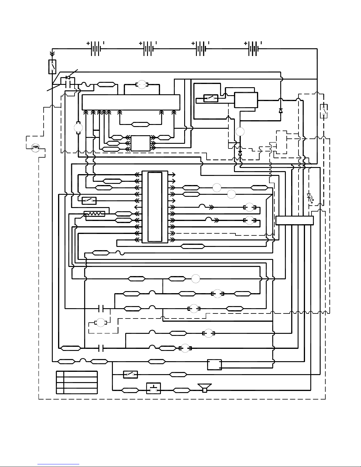
WIRING GROUP-SCHEMATIC
MAIN
CONTACTOR
RED 1
(OPT)
LIGHT
BLK 2
RED
EMERGENCY
SWITCH
M1
DIODE 29215
FUSE
200A
FAN
WHT 29
FWDREV 12 13 2 1
BLK 6
WHT 4
WHT/BLK
WHT/BLK 2
RED 3
FLOAT SWITCH
BLK
SHUNT
YLW
WHT 28
8A
M2
FWD
REV
GRAY
WHT/RED
GRAY
BRN 7
TAN 8
GRAY
WHT/TAN
FUSE
TRACTION
MOTOR
PM
CONTROLLER
TAN 23
THROTTLE
MODULE
P1 TOUCH PAD
112 1
6
71887
819
920109
10
11
M1
4
RED 4A
12
2132
13
14
1433
4154
15
165
5
16
6
17
17
18
19
20
21
21
22 11
22
B-
15
WHT/ORG
WHT/BLK
WHT/YLW
BLU 14
PUR 15
LT BLU
GRN
BLK
WHT/TAN 11A
SEAT
SWITCH
WHT/GRAY 16
BLK 32
RED
CONT COIL
BRUSH
CONT COIL
CB 7
15A
CB 6
15A
BLU 8
M2
VAC
GRN 7
RED
880206
WHT/TAN
WHT/GRAY 33
2
TIMER
1
NC
M2
ORG 6
M3
SCRUB BRUSH
ACTUATOR
PM
PM
SQUEEGEE
ACTUATOR
6
NO
C
WHT 880204
MAIN
CONT COIL
BRN 24
BLK 880093
RECYCLE BOARD
(OPT)
NEG
PMCTL
PM+
PWR
RED 5
BLK
TERMINAL
BLOCK
RED 82687
BLK 4
(OPT)
LED
(OPT)
REC
FLT
B
L
K
3
WHT/RED 4
PNK 27
LEGEND
CB
CIRCUIT BREAKER
PM
PERMENANT MAGNET
RELAY (CONTACTOR)
M
ARM
ARMATURE
SCRUB BRUSH
CONTACTOR
VACUUM MOTOR
CONTACTOR
CB 8
3A
M2
PUMP (OPT)
M3
BLU 23B
RED 1
GRN 880205
YLW 9
PUR 26
PUR 25
WHT 2
GRN 880206
KEY
SWITCH
BLU 23A
CB 4
35A
CB 3
35A
CB 1
25A
CB 2
25A
BLU 23
HORN
SWITCH
GRAY
RED 12
YLW 13
BLU 15
FRONT VACUUM
MOTOR
RED 24
ORG 25
NOTE: OPTIONAL ITEMS SHOWN IN HIDDEN LINES.
SOLUTION VALVE
SOLENOID
M4
YLW 19
RIGHT SCRUB
BRUSH MOTOR
PM
REAR VACUUM
MOTOR
PM
HORN
LEFT SCRUB
BRUSH MOTOR
PM
PM
HOUR
METER
12
3
BLK
BRN 20
BRN 22
GRAY
BLK
BLK
BLK
GRAY
BLK
QUICK 98560 09/29/00
4-14
 Loading...