

Page 1
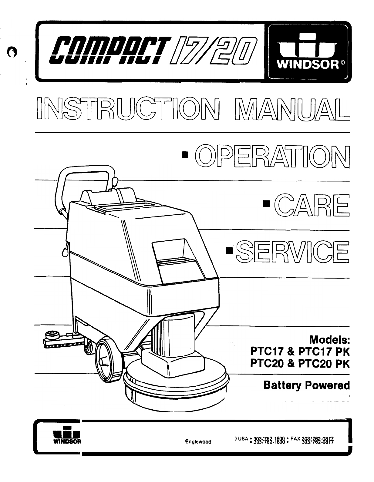
Floor Scrubber
INDUSTRIES, INC., 1351
W.
Stanford Ave., Englewood,
CO
80110
USA 303/762-1800 FAX 303/762-0817
Page 2
Operator Safety Instructions
Read the instruction manual before operating this
machine.
Operate this machine only from the rear of machine.
Use caution when operating the machine on a ramp
or incline.
on a ramp or incline.
Machine can cause an explosion when operated near
flammable vapors and materials.
Do
not turn or leave this machine unattended
Store machine inside. Keep the electrical components
of the machine dry.
Lead acid batteries generate gases which can cause
an explosion. Keep sparks and flames away from the
batteries. Charge the batteries only in a well ventilated
area.
Wear eye protection when working near batteries.
not put any type of metal objects across the battery
or
terminals
Maintenance and repairs must be done by qualified
personnel only. Maintain adjustments on machine
as per specifications noted in the service manual.
Make sure all warning and caution labels are legible
and properly attached to the machine.
on top of the batteries.
Do
Page 3
‘I
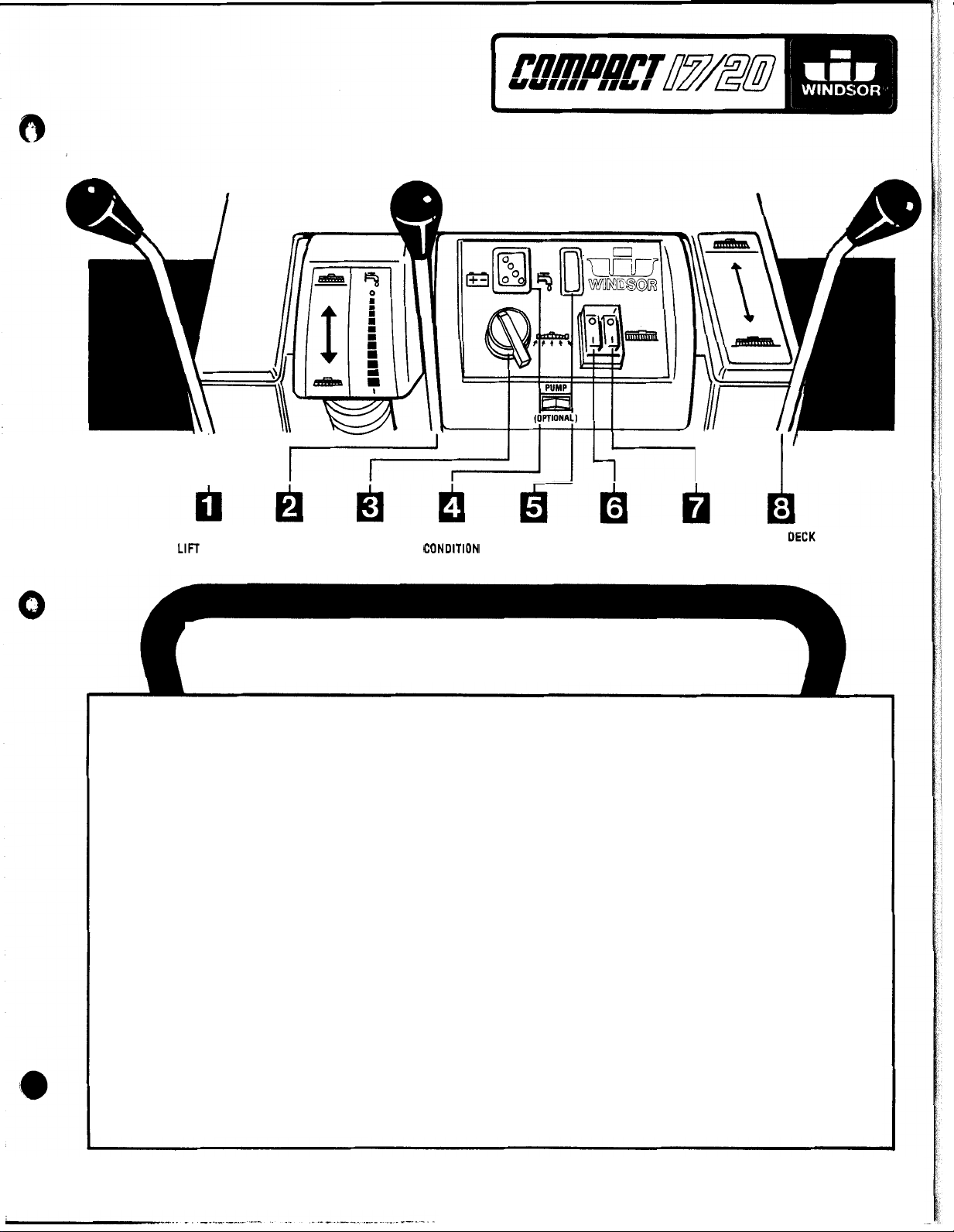
SQUEEGEE SOLUTION MAIN BATTERY SOLUTION VACUUM BRUSH SCRUB DECK
LEVER LIGHT LIGHT SWITCH SWITCH
OPERATOR CONTROL HANDLE
1.
Raises and lowers squeegee assembly.
2.
Controls flow of cleaning solution to floor.
3.
Controls electric power to all switched components.
4.
Indicates charge condition of batteries.
5.
Light
6.
Switches on vacuum motor.
7.
Switches on brush drive motor.
8.
Raises and lowers scrub deck assembly.
“ON”
indicates solution valve is open.
3
.
Page 4
MACHINE PREPARATION
BATTERIES
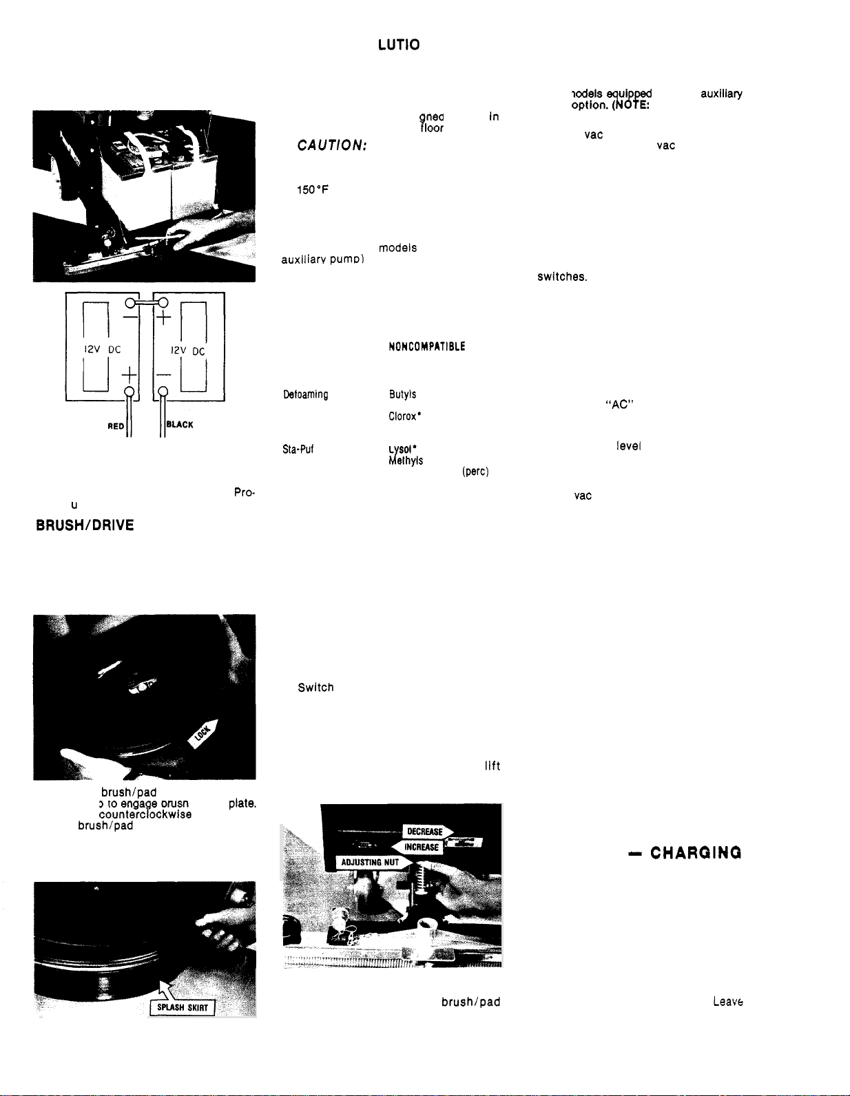
1.
Install batteries and connect battery
cables as shown.
WARNING:
leave door open when charging batteries.
2.
Charge the batteries before using the
machine. (See Battery Charging
ced
1.
Raise scrub deck assembly by raising
control lever to store position.
2.
Reach under scrub deck and rotate drive
plate until a lug hole is visible through
scrub deck sight hole.
3.
Positlon brush/pad driver under plate
and lift up to enga e brush lugs in
A
quick countercyockwise motion will
lock
4.
Lower scrub deck by pulling control
lever rearward. Adjust splash skirt to
floor.
Provide proper ventilation,
re)
CLEAN I N G
1.
Fill machine with hot water and add
cleaning chemical at the proportion
noted on the container.
CAUTION:
cleaning chemical desi ned for use In
automatic hard surface ?loor scrubbers.
tortion of polyethylene solution/
recovery tanks. DO NOT USE WATER
TEMPERATURE THAT EXCEEDS
(65°C).
SO
Always use a
To avoid possible dis
low
sudslng
CHEMICALS
The internal parts of the pump used in
the scrubber (on
most cleaning chemicals. But it is
ceptible to chemical attach from some
cleaning substances, such as hydro
carbon solvents and chlorinated bleaches.
These noncompatible materials are not
of the type normally used for cleaning.
SUITABLE
CHEMICALS CHEMICALS
Alkalis
Clorox
ii
Bleach’
Detergents Carbon Tetrachloride
Hydroxides
Oxygen Bleaches
Soaps
Vinegar
White Monday Bleach’ Perchlorethylene (perc)
*Registered Trademark
Agents
Fabric Softener’
OPERATING
1.
Adjust the operator control handle to
a comfortable position.
2.
Switch on main power switch.
3.
Release solution. Pull solution control
lever rearward.
solution can be regulated during oper
ation depending on the type of floor
and the traverse speed of the machine.
4.
Switch on brush drive motor.
5.
6.
Lower scrub deck. Pull deck lift lever
rearward.
CAUTION:
on floor while machine is stationary.
7.
Lower squeegee. Pull squeegee lift
lever rearward.
knob to change pressure on squeegee.
8.
Push machine forward to begin clean
ing. Forward motion is assisted by the
scrubbing action of the
driver.
Aldehydes
Aromatic Hydrocarbons
Chlorinated Bleaches
Chlorinated Hydrocarbons
L
(MEK)
Phenols
Trichlorethylene
D-Limonene
THE
MACHINE
NOTE
The amount of
DO
not leave brush running
NOTE
Use adjusting
sus
OPERATING MACHINE
WITH ACCESSORY
The
HFT
used
pump kit optionTPed E Factory installed
option only.)
1.
-
2.
3.
4.
5.
-
-
floor tool for wet pick-up can be
on models with the
Remove vac hose from squeegee and
connect to accessory
metal hose coupler.
Connect solution hose from accessory
tool to solution outlet nipple located at
lower right hand corner of rear panel.
Check solution tank for cleaning solu
tion and make sure dome is in place.
Switch on main power switch.
Switch on auxiliary pump and vacuum
WARNING:
motor when operating machine with
accessory tools.
Do not switch on brush
REGULAR MAINTENANCE
BEFORE STARTING
1.
Disconnect battery charger.
connect the “AC” power cord from the
wall receptacle before removing the
“DC” charger plug from machine.
2.
Check water level in batteries. Add
distilled water as needed.
3.
Attach brush or drive pad to drive plate.
4.
Check vac hose connection at squeegee
shoe.
5.
Check squeegee blades for wear.
6.
Fill machine with hot water and add
cleaning chemical at the proportions
noted on the container.
low
sudsing cleaner designed for use in
automatic hard surface floor scrubbers.
BEFORE STORING MACHINE AT
THE END
-
1.
2.
3.
4.
5.
6.
Drain both solution and recovery tanks
and rinse clean.
Remove dome, lift out float assembly
to allow recovery tank to air dry.
Remove brush or drive pad from drive
plate and store upside down or hang
on wall.
Wipe down exterior of machine with
damp cloth.
Raise squeegee assembly to “store”
position.
Charge batteries. (See Battery Charging
Procedure)
OF
WORK
WORK
NOTE
PERIOD:
BATTERIES
AND MAINTENANCE
BATTERY CHARGING PROCEDURE
WARNING:
gases which can cause an explosion. Keep
sparks and flames away from batteries.
NO
SMOKING.
when working near batteries. Charge the
batteries only in a well ventilated area.
-
1.
Set the charger on a flat level surface.
2.
Open bettery compartment door.
door open during charging cycle.
Lead acid batteries generate
Always wear eye protection
TOOL
PERIOD
NOTE
Dis
Use a
-
-
4
Page 5
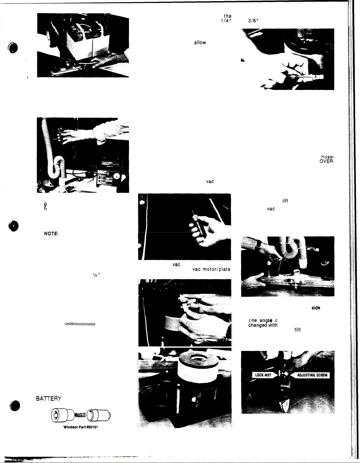
3.
Connect the “DC” charger plug to the
connector on the machine.
safety override switch is activated
when the “DC charge plug is connected.
This prevents all panel circuits on the
machine from accidentally being
switched on during charging cycle.
4.
Connect charger “AC” plug to properly
rounded outlet that has correct voltage
or the charger.
5.
The charger suppled by Wlndsor is
totally automatic and shuts off when
the batteries are fully charged.
Refer to the charger manual for
detailed charging information.
6.
After charging check electrolyte level
of the batteries. Add distilled water to
the level as shown in diagram.
NOTE
FROM
BOTTOM
OF TUBE
3.
Keep the battery electrolyte at th$
correct level - approximately
below bottom of filler tube of each cell.
Distilled water should be added, as
needed,
WARNING:
level to drop below the tops of the plates.
AFTER
charging cycle.
Do not allow electrolyte
SERVICING THE
COMPACT SCRUBBER
CAUTION:
ments or repairs to the machine.
A
1.
Only qualified maintenance personnel
are
2.
Make sure battery charger is discon
nected.
3.
Make sure all switches are “OFF”.
4.
Remove batteries as required or discon
nect main battery leads from batteries
when making repairs to electrical system.
5.
Refer to wiring diagram when replacing
electrical parts or repairing electrical
system.
VACUUM
1.
Disconnect battery leads and remove
batteries from compartment.
2.
Remove
plate assembly to recovery tank.
3.
Disconnect vac motor lead from con
nector and lift out vac motor/plate
assembly.
Before making any adjust
to
perform repairs.
MOTOR
(6)
screws holding vac motor/
4.
Check motor brushes. When worn to
replace both brushes.
-
.
.
PUMP
(On models equipped with auxiliary pump)
1.
-
2.
ASSEMBLY
Remove batteries and squeegee as
sembly. Lay machine on side.
Disconnect pump motor leads. Re
move
(4)
chassis. Disconnect solution hoses
from pump head and lift out pump.
Refer to pump drawing for replace
ment parts.
CAUTION:
barbs on pump head-DO NOT OVER-
TIGHTEN-as this could crack intake
and exhaust ports in pump head.
screws holding pump to
When replacing hose-
-
-
-
SQUEEGEE ASSEMBLY
To remove squeegee assembly.
1.
Raise squeegee lift arm to store position.
2.
Remove vac hose from squeegee.
3.
Pull retaining pin from locator stud.
Push down and slide squeegee to the
right to disengage right hand stud from
drag arm.
-
.
BATTERY MAINTENANCE
1.
Keep tops of batteries clean and dry.
Use a damp cloth with a weak solution
of baking soda or ammonia and water.
Use a clean dry cloth to wipe battery
tops dry after cleaning.
2.
If corrosion (white deposits) appears
on the battery terminals and cable
clamps, remove and clean. Use a battery
terminal and connector cleaning tool.
4.
When installing or replacing squeegee
blades make sure the
blade is next to the squeegee casting.
5.
The an
screw clockwise to
ward and counterclockwise to tilt rear
ward. Tighten lock nut after making
adjustment.
6.
Down pressure can be increased or
decreased with the adjusting nut.
of the squeegee can be
smooth
of the
-
-
5
Page 6

Squeegee tracking can be controlled
springs.
as shown before making adjustments.
:
Position
recovery
hose
SCRUB DECK/BRUSH
MOTOR
1.
Remove
shroud.
(4)
screws holding motor
4.
Disconnect motor leads from terminal
block.
5.
Remove
to scrub deck.
(4)
screws holding brush motor
Use allen wrench to remove wheel
retaining screw.
Use arbor press to replace bearings as
2.
required. Use grease gun to lubricate
bearings through zerk fitting on wheel
hub and caster axle.
2.
Remove batteries and squeegee as
sembly. Lay machine on side.
3.
Remove center screw holding drive
plate. Slide drive plate off motor shaft.
Limited
Warranty:
Windsor machine covered
Brush
-
6.
Windsor Industries warrants that the
Motor
Remove
end bell. Replace brushes when worn
to
(2)
motor thru-bolts and lift off
inch.
by
this warranty is free from
defects in workmanship and
terms:
6
Chassis and Metal Frames.
year
On Rotationally Molded Polyethylene Tanks.
On Traverse Drive Motors, Gear Units, AC Induction Polisher Motors, all Metal
On all other parts which are not specifically referenced herein, plus an extra
(2
years total) on Rectified DC Polisher Motors and Scrubber Brush Motors.
SOLUTION STRAINER
An inline solution strainer is located
under chassis behind left wheel. Re
move sediment bowl and screen period
ically and rinse clean with hot water.
6
The warranty period shall commence at the date of FIRST PURCHASE BY THE END USER
FROM AN AUTHORIZED
to failure caused by abuse or normal wear.
Windsor will, at its option, repair or replace without charge, except for normal transportation
costs, parts that fail under normal use and service when operated and maintained in accord
ance with the Owners Instruction Manual and the Preventive
applicable. This warranty shall apply to defects in material and workmanship only and
-
does not apply to:
-
c) misuse or abuse (including use of incompatible or corrosive chemicals or overloading of
capacity), d) failure caused by lack of proper maintenance and cleaning,
chargers which are warranted by the original manufacturer for one year, and
wear on items such as belts, brushes, bearings, capacitors, carbon brushes, clutches,
cords, filters, finishes, gaskets, hoses, pulleys, relays, rectifiers, and switches.
The warranty is in lieu of all warranties, expressed or Implied, and releases Windsor from all
other obligations and liabilities. It is applicable only in the U.S.A., Canada, Australia, and
New
to damage or
APPROVED BY
If
a difficulty develops with this machine, contact either the Dealer from whom you
purchased the product or write to:
a) transportation damages, b) alterations by unauthorized persons,
loss
of income due to malfunctloning of the machine. USE
WILL
VOID WARRANTY.
Maintenance Guide where
OF
PARTS NOT
-
f) normal
Page 7

27
TANKS,
VAC
FRAME
39
KEY
PART
NO.
DESCRIPTION
1 70020 Scr, 1/4-20 x 112 HHMS
2 61181 Panel, Rear
3 87090 Washer, 1/4 Flat
4 70010 Scr, 1/4
5
34188 Frame, Main
6 57119 Nut, 3/8
-
20 x 1.5 HHCS
-
16 Lock
7 18027 Caster
8 70266 Scr,
-
9 70327 Scr, 1/4
20 x 3/8 THMS
10 27266 Cap, Wheel Hub
11 09010 Bearing, Caged Cup Needle
12 89068 Wheel (With
13 73437 Spacer, Wheel
14 27408 Collar,
Axle
Axle
15 70119 Set Scr, 1/4-20 x 3/8 KCP
Axle,
Wheel
17 75152 Tank, Solution
18 50363 Label, Solution Warning
19 27416 Cord, Solution Lid
20 51138 Lid, Solution Tank
21 75153 Tank, Recovery
TANKS,
KEY PART
VAC
NO.
DESCRIPTION
FRAME
22 57047 Nut, 1/4-20 Ny-Lock
23 73427
Float
24 67227 Rod, Vac Float
25 73423 Screen, Float
26 27142 Cap Nut,
27 34190 Float
Asm,
28 35060 Gasket, Dome
29 28040 Lid, Recovery Tank
30 27417 Cord,
"
31 29154 Deflector, Vac Intake
32 70233 Scr,
PH Hi-
33 20046 Clamp, 2.25 Hose
34 27188 Cord, Drain Hose Plug
35 66051 Plug, Drain Hose
36 40019 Hosebarb, 1.5 Double
37 20002 Clamp, 2" Nylon
"
38 39037 Hose, 1.5 x 24
39 39383 Hose
40
27282 Cuff, 1.5 Slip x 1.5 Hose
41 70085 Scr, 1/4
Asm,
-
Drain
20 x 1/2 PHMS
42 87025 Washer,
-
Off
LO
KEY
PART
NO.
7
Page 8

SCRUB
DECK
‘74
24
A0
8
Page 9

PARTNO. DESCRIPTION
1/4
ID
2 87090 Washer,
3
48012 Knob, Adjustment
4A 14676 Bumper, PTC17 Brush Shroud
Bumper,
I
5A 02162
02098 Pad Driver,
02169 Pad Driver Asm, 18" Weighted
6 70304 Scr, W14x 1.25 FHWS
7
51076 Lug, Brush Mtg
8
41200 Synthetic Pad Lock
9 70233 Scr,
02115 Brush Asm, 16" Nylon
Pad Driver, 16
Pad Driver
x
"
Ylw
"
18
"
Blk Pad Lock
x
3/8 PH Hi-Lo
Pad Lock
Weighted
Flat
DECK
DESCRIPTION
PARTNO.
DESCRIPTION
I
I
BATTERY COMPARTMENT
PARTNO. DESCRIPTION
BATTERY COMPARTMENT
9
Page 10

ELECTRICAL
CONTROLS
,
26
27
28
29
10
Page 11

MECHANICAL CONTROLS
24
13
41
I.
34
I
30
-
3
22
32
I
PART
NO.
1
29151
2 66068
3 67226
4 73236
5
27413
6 66121
7 661 16
8
70020
9 27401
10 70025
11
57030
12 51125
13 67138
14 48030
DESCRIPTION
Door. Battery Compartment
Pin,
x
Roll
Rod, Battery Door Lock
Spring,
1.12
Cable, Battery Compartment Door
Pin,
Pin,
Scr,
Cable, Solution
Scr,
Nut,
Lever, Solution
Ring,
Knob, Handle
Compression
3/32 x 1/2
1/4 x 3/4
1/4-20
Cotter
Clevis
x
10-32 x 3/4
10-32
Ext
Snap
HHMS
HHMS
MECHANICAL CONTROLS
15
27460
16 70298
17 87029
19 87030
20 66144
21 57006
22 70119
23 67221
24 14679
25 50473
26 57032
27 87080
28 78220
29 38169
Cable, Squeegee
Shoulder Bolt,
Washer,
Washer,
Pivot, Cable
Nut,
1/4-20
Set Scr,
Rod, Main Lever
Bushing, Lever Pivot
Card, Instruction
Nut,
3/8-16
Washer,
Tube, Handle Adj
Handle, w/Foam Grip
5/16
5/16
Flat
3/8 x 3/4
Hex
1/4-20
x
Serrated Flange
Flat
Nylon
OD
KCP
PARTNO. DESCRIPTION
x
L
31 51142
33 67228
34 66133
35 87018
36 66073
37 50477
38 61181
39 57105
40 70018
41 87003
42 36059
30 67224
Rod, Handle Adjust
Cable, Scrub Deck
Rod, Scrub Deck Lift
3/16
x
.88
Washer,
Pin,
1/16 x 3/4
Label, Charger Warning
Panel, Rear
Nut,
1/4-20
1/4-20
Washer,
Grip,
MX
Flat
Hex w/Star
x 1 HHCS
5/16
Flat
Handle
L Clevis
L
Cotter
11
Page 12

SQUEEGEE
SQUEEOEE
LIFT
MECHANISM
I
Frame
-
Frame
KEY PART
1
2
3 89058 Wheel, Squeegee Roller
4 66108
5
6 14482 Brkt, Squeegee Wheel
7 70011 Scr, 1/4
8 87025 Washer,
9
12 73428 Squeegee Shoe
13A 73415 Squeegee Blade, Front
14 57085 Nut, 3/8
16 66092 Pin, Hair Spring Cotter
17 70098 Scr, 8
NO.
OESCRIPTION
67103 Ring, 5/16
87029 Washer, 5/16 Flat
57112
70020 Scr, 1/4-20 x 1/2 HHMS
67217 Retainer, Squeegee
73416 Squeegee Blade, Rear
02165 Squeegee Blade, Urethane
14483 Bolt, Squeegee Stud
Nut, 5/16-18 Flange
-
32 x 318 PHST
Snap
Wheel
-
20 x 5/8 HHMS
-
16 Hex Jam
SQUEEGEE
36 27382 Collar, Squeegee
SQUEEGEE
PART
NO. OESCRIPTION
LIFT
MECHANISM
I
KEY PART
I
4
NO.
12
Page 13

AUXILIARY
3
20
PUMP
MODEL
PLUMBING
28
27
Note:
i
I
machine laying
on right side.
STANDARD MODEL
Plumbing
6
I
13
Page 14

TROUBLE-SHOOTING
PROBLEM PROBABLE CAUSE CORRECTIVE ACTION
No
power.
Battery cables corroded
at battery terminals.
Faulty main switch.
Faulty safety override
switch.
GUIDE
1. Clean battery cable clamps and battery terminals.
2.
Check voltage at points A and B. Voltage should be
1. Check voltage at points
2.
Turn main switch on and check voltage at points B and D. Voltage should be
22/26
VDC.
If
no voltage remove leads and check switch for continuity.
With main switch
at B and
tinuity in normal position and no continuity when switch is activated.
H
“ON” check voltage at points B and
remove leads and check micro-switch for continuity. Should have con
B
and C. Voltage should be
22/26
22/26
G,
and B and
VDC.
VDC.
H.
If
no voltage
-
Vacuum motor
does not run.
Brush motor
does not run.
Solution
does not work.
Circuit breaker tripped.
Loose connection.
Faulty
Faulty
Faulty
breaker.
Motor brushes worn.
Circuit breaker tripped.
Loose connections.
Faulty brush switch.
Faulty brush relay.
Faulty brush circuit
breaker.
Motor brushes worn.
Loose connections.
Faulty solution light.
Light stays on with
solution lever in
“OFF” position.
Reset
Check motor lead connections at terminals.
Remove leads and check switch for continuity. Replace as needed.
Voltage should be
With main switch
Voltage should be
Check motor brushes.
and motor secured
motor should be
Reset circuit breaker.
Check motor leads at terminal block connections (located on inside front of frame).
Tighten screws as needed.
Remove leads and check switch for continuity. Replace as needed.
With main switch
Voltage should be
With main switch
Voltage should be
Check motor brushes. Replace when worn
and motor secured, apply battery voltage directly
motor should be
Check for loose connections at solution light, solution switch and at
ground.
Remove light and apply direct voltage
Adjust solution light switch.
“ON”
22/26
“ON”
22/26
,
apply ’battery voltage directly
6.2
amps.
“ON”
and brush switch
22/26
“ON”
22/26
6
to
8 amps.
(20
amp).
and vac switch “ON” check voltage at points B and
VDC.
and vac switch
VDC.
VDC.
and brush switch
VDC.
(24
“ON”
check voltage at points B and
to
“ON”
“ON”
to
VDC)
With batteries fullv charaed
to
motor.
check voltage at points B and
check voltage at points B and L.
to
motor.
to
light. Replace light as needed.
No
load amp draw of
No
load amp draw of
K.
I.
J.
Battery charge
does not light.
14
Loose connections.
Faulty PC Board or
faulty light.
-
Check connections at battery card, micro
ground connection at
Check voltage into PC Board (point
across first pin (from right) and eighth pin (from right) point
8/10
VDC. If voltage is 8/10 VDC replace battery charge level indicator light. If
there is no voltage replace PC Board.
T).
switch at charger Connection, and
Voltage should be
22/26
VDC. Check voltage
U.
Voltage should be
Page 15

POWER
SWITCH SWITCH LIGHT
SOLUTION SOLUTION LIGHT BATTERY LEVEL
SWITCH
WIRING
DIAGRAM
VACUUM
MOTOR
PUMP SWITCH
CHARGER
CONNECTION
I
PUMP MOTOR
(OPTIONAL)
I
Plug
66017
Housing
41010
Pump
I
I
Assembly
Pump Repair
Cover
65019
Kit
62053
47020
Base
-
I
Pump
Motor
PUMP
53188
15
 Loading...