

Page 1
Page 2
Operator Safety Instructions
Read the instruction manual before operating this
mac h i ne.
Operate this machine only from the rear of machine.
~ ~~~~ ~~~
Use caution when operating the machine on a ramp
or
incline.
on a ramp or incline.
Machine can cause an explosion when operated near
flammable vapors and materials.
Do
not turn
or
leave this machine unattended
~
'
~ ~~
Store machine inside. Keep the electrical components
of the machine dry.
~ ~ ~~
Lead acid batteries generate gases which can cause
an explosion. Keep sparks and flames away from the
batteries. Charge the batteries only in a well ventilated
area.
~ ~ ~~ ~~ ~
Wear eye protection when working near batteries.
Do
not put any type of metal objects across the battery
or
terminals
on top of the batteries.
Maintenance and repairs must be done by qualified
personnel only. Maintain adjustments on machine
as per specifications noted in the service manual.
Make sure all warning and caution labels are legible
and properly attached to the machine.
2
Page 3
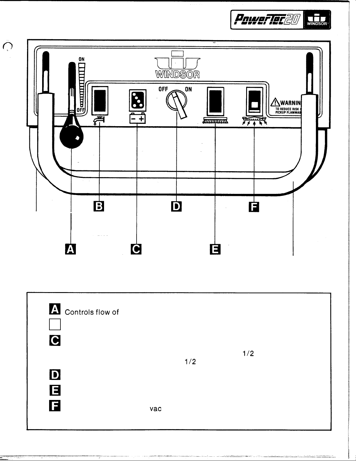
CONTROL
HANDLE
SOLUTION
“ON”
I
LIGHT
MAIN
SWITCH
LIGHTED
VACUUM
SWITCH
SOLUTION
CONTROL
LEVER
Controls flow of cleaning solution to floor.
Light
Indicates charge condition of batteries
Switches on main drive motor and brush.
Light
Lighted switch indicates vac motor is on.
“ON”
4
green lights - full charge - approximately
1
green light - approximately
“ON”
BATTERY
CONDITION
LIGHTS
indicates solution valve is open.
indicates brush is turning.
BRUSH
“ON”
LIGHT
-
112
hour run time left.
4
TRAVERSE
112
hours run time.
CONTROL
HANDLE
3
Page 4
,
MACHINE PREPARATION
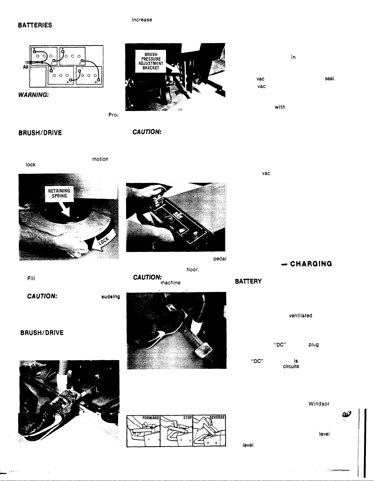
BAITERIES
1.
Install batteries and connect battery
cables as shown.
RE
MfARN/NG:
leave cover open when charging batteries.
2.
Charge the batteries before using the
machine. (See Battery Charging
ced u re)
Provide proper ventilation and
BRUSH/DRIVE PAD ASSEMBLY
1.
Remove brush cover.
2.
Position brush under drive plate and lift
brush to engage drive lugs in recesses
in plate.
lock brush to drive plate.
A
quick clockwise motion will
FRONT
Pro-
NOTE
This pedal can also be used to
Increase brush pressure to the floor.
This can be done by pulling up on the
pedal and locking it in one of the posi
tions on the brush adjustment bracket.
2.
Switch on brush motor by turning the
main switch clockwise.
CAUTION:
on floor while machine is stationary.
3.
Switch on vacuum switch.
4.
Push solution lever forward.
amount of solution can be regulated
during operation depending on the type
of floor and the traverse speed of the
machine.
Do
not leave brush running
NOTE:
REGULAR MAINTENANCE
BEFORE STARTING
-
1.
Disconnect battery charger.
connect the “AC” power cord from the
wall receptacle before removing the
“DC” charger plug from machine.
2.
Check water level In batteries. Add
distilled water as needed.
3.
Attach brush
4.
Check vac motor and float for proper seal.
5.
Check vac hose connection at squeegee
shoe.
8.
Check squeegee blades for wear.
7.
Fill machine with hot water and add
cleaning chemical at the proportions
noted on the container.
sudsing cleaner designed for use in
automatic hard surface floor scrubbers.
BEFORE STORING MACHINE AT
The
THE END
1.
Drain both solution and recovery tanks
and rinse clean.
2.
Lift out vac motor and float assembly
to allow recovery tank to air dry.
3.
Remove brush or drive pad from drive
plate and store upside down or hang on
wall.
4.
Wipe down exterior of machine with
damp cloth.
5.
Raise squeegee assembly to “store”
position.
8.
Charge batteries. (See Battery Charging
Procedure)
OF
WORK
or
drive pad to drive plate.
WORK
PERIOD
NOTE
NOTE
Use a low
PERIOD:
Dis
-
CLEANING SOLUTION
1.
Fill machine with hot water and add
cleaning chemical at the proportion
noted on the container.
CAUTION:
cleaning chemical designed for use in
automatic hard surface floor scrubbers.
OPERATINO
Always use a
THE
MACHINE
low
rudsing
BRUSH/DRIVE PAD CONTROL
1.
Push down and slightly to the left on
brush lift arm to lower brush to floor
(right hand pedal).
4
5.
Push down on front of squeegee pedal
to release the latch arm and lower
squeegee assembly to
CAUTION:
moving the machlne in
vent damage to squeegee blades.
8.
To
go
traverse handle.
STOP
To
pull back on the control handle.
To
REVERSE
handle.
Always lift squeegee before
FORWARD
release the traverse handle and
machine lift up on traverse
floor.
REVERSE
press down on the
to pre
BATTERIES - CHAROINQ
AND MAINTENANCE
BAITERY CHARGING PROCEDURE
-
WARNING:
gases which can cause an explosion. Keep
sparks and flames away from batteries.
SMOKING.
when working near batteries. Charge the
batteries only in a well
1.
Set the charger on a flat level surface.
2.
Lift
cover up during charging cycle.
3.
Connect the “DC” charger plug to the
connector on the machine.
safety override switch is activated when
the
prevents all panel circuits on the machine
from accidentally being switched on
during charging cycle.
4.
Connect charger “AC” plug to properly
grounded outlet that has correct voltage
for the charger.
5.
The charger supplied by Windsor is
totally automatic and shuts
batteries are fully charged.
NOTE:
detailed charging information.
8.
After charging check electrolyte level
the batteries. Add distilled water to the
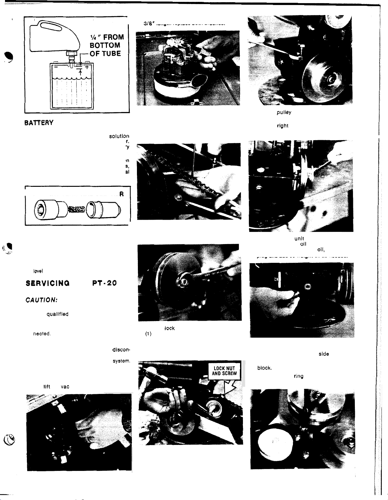
level as shown in dlagram. (upper right)
Lead acid batteries generate
Always wear eye protection
ventilated area.
up battery compartment cover. Leave
NOTE
“DC’
charge plug Is connected. This
off
when the
Refer to the charger manual for
NO
A
Of
Page 5
BATTERY MAINTENANCE
1.
Keep tops of batteries clean and dry.
Use a damp cloth with a weak
of baking soda or ammonia and water.
Use a clean dry cloth to wipe battery
tops dry after cleaning.
2.
If
corrosion (white deposits) appears on
the battery terminals and cable clamps,
remove and clean. Use a battery terminal
and connector cleaning tool.
SOlutlOn
2.
Check motor brushes - when worn to
318"
length replace both brushes.
DRIVE CHAIN
1.
Remove left side skirt and side panel.
2. To
remove chain, remove retaining clip
and pull out master link.
2.
Remove pulley to allow removal of left
hand lift arm.
3.
Remove right hand pivot bolt, bushing
and lift arm.
BATTERY TERM
3.
Keep the battery electrolyte at the
correct level
bottom of filler tube of each cell. Dis
tilled
water should be added, as needed,
AFTER
charging cycle.
WARNING:
level to drop below the tops of the plates.
SERVlClNQ
I
N
AL CLEAN E
-
approximately
Do not allow electrolyte
THE
114
PT-20
SCRUBBER
CAUTION:
ments or repairs to the machine..
1.
Only qualified maintenance personnel
are to perform repairs.
2.
Make sure battery charger is dlscon
nected.
3.
Make sure all switches are
4.
Remove batteries as required or dlscon-
nect main battery leads from batteries
when making repairs to electrical
VACUUM
1.
Disconnect motor leads from connector
and
Before making any adjust
MOTOR
lift out vac motor.
"
.
OFF
R
"
below
"
system.
3.
To
adjust chain tension
A.
Remove traverse drive pulley.
-
-
B.
Loosen lock nut and back out screw
-
(I)
turn.
C.
Use a hammer and punch to rotate
the eccentric bushing to tighten or
loosen the drive chain.
. . .
4.
To
check gear unit oil level - remove
Inspection plug;
bottom of hole.
plug and add
TRAVERSE DRIVE
1.
Remove lower right hand side skirt.
2.
Disconnect motor leads from terminal
block.
3.
Remove snap ring from end of motor
pivot shaft.
oil should be at the
To
add
011,
90
welght oil as needed.
remove
MOTOR
fill
QEAR
1.
UNIT
Loosen belt tension screw and remove
belts.
5
Page 6
4.
Lift out motor - check motor brushes.
When worn to
318"
replace brushes.
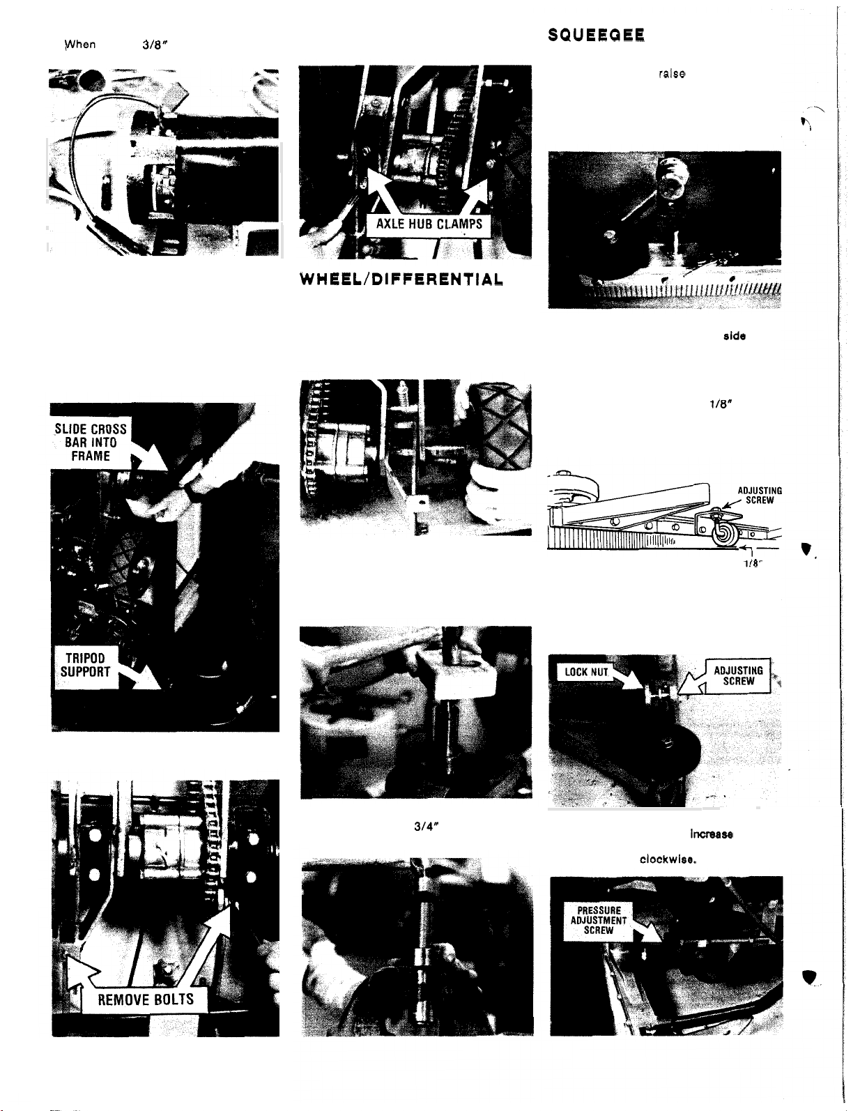
3.
Remove axle hub clamps. Lift
bly and lay on bench to service.
off
assem
-
SQUEEQEE ASSEMBLY
To
remove squeegee assembly.. .
1.
Depress pedal to raise squeegee.
2. Pull retaining pin from locator stud.
3.
Push down on squeegee to remove from
drag arm and slide squeegee to the right
to disengage right hand stud from arm.
DIFFERENTIAL ASSEMBLY
NOTE:
The differential assembly, traverse
drive motor and brush gear unit can be
removed as a total unit for servicing, if
required.
1.
Lay machine on side or build tripod
supports for each side of machine to
hold unit upright as shown.
WHEEL/DIFFERENTIAL
AXLE ASSEMBLY
1.
Remove bolt holding wheel to axle.
2.
Remove wheel from axle. Use wheel
if
puller,
damage threads in center hole of axle.
3.
To
A.
B.
needed, being careful not to
remove axle and bearings from hub ...
Remove snap ring from hub.
Use an arbor press or hammer and
block of wood to remove bearing and
axle.
4.
When installing or replacing squeegee
blades make sure the smooth
blade is next to the squeegee casting.
5.
Squeegee support caster - with
squeegee assembly setting perpendicular
to the floor surface, adjust caster to a
clearance of approximately
bottom of caster and the floor.
squeegee blades wear, adjust caster to
maintain this dimension.
6. The angle of the squeegee can be
changed with the adjusting screw. Turn
screw clockwise to tilt squeegee forward
and counterclockwise to tilt rearward.
Tighten lock nut after making adjustment.
1/8"
slde
between
As
1/0"
of the
the
2. Remove boits from brush lift arm bracket
and traverse drive connecting arm.
6
C.
To
remove roiler bearing from hub,
use a piece of
out bearing.
314"
dia. tube to drive
7.
Squeegee pressure can be changed with
the adjusting screw.
turn counterclockwise, to decrease
pressure turn
To
clockwise.
Increase
pressure
Page 7

CAUTION:
excessive pressure on the squeegee will
cause abnormal wear on the squeegee
blades.
BRUSH DRIVE BELT
‘\
1.
Remove traverse drive belt by rolling belt
off pulley.
2.
Loosen belt tension adjusting screw and
remove brush drive belt. After readjust
ing belt tension, make sure lock nut on
adjusting screw Is tight.
Operating the machine with
TRAVERSE DRIVE BELT
1.
With operating handle in neutral position,
roll belt off pulley. Replace as required.
2.
After installing new belt check for clear
ance between traverse pulley and brush
drive belt. The pulley should not be in
contact
handle is in the neutral position.
To
A.
B.
-
with the belt when the traverse
adjust clearance:
Remove left side panel.
Loosen lock nuts on link rod. Adjust
bracket on link rod
contact belt. Retighten lock nuts on pletely on the floor.
link rod.
so
pulley does not Springs will allow the brush to rest com
BRUSH ANGLE
-
ADJUSTMENT
- -- - -
1.
2.
3.
4.
-
~ ~
Start
the
brush
motor
brush slowly to the floor. When the rear
of the brush
front of the brush
3/16”
BY releasing the foot lift pedal the
A.
If
the brush vibrates while in opera-
tlon
B.
If
the machine pulls to the left during
operation
The springs
to maintain the distances
To
change brush inclination, IOOSen nut
(D)
and turn tie-rod
angle
“A”
from the floor.
Increase dirtanu
decrease dlrtanu
(C)
should be adjusted
Is reached.
and
touches the floor, the
“8”
should be about
(E)
until the correct
A
“B”.
as
lower
“B”.
shown.
so
the
-
as
Page 8

'
VAC,
BATTERY,
TANK
REV
VAC,
PARTNO.
BATTERY,
mnitvion
TANK
7
/
32
9
70280
Stud,
1/4 Turn Fastener
Scr,
10 70076
11 51074 Lug,
12 48012 Knob, 5/16
10-32 x 1 FHMS
Shroud
Mounting
-
18
8
Page 9

17
A
I
16
9
Page 10

'
MAINFRAME
WITANKS
34
38
37
36
35
I
41'
io
13
14,
"1
/
39
46
Page 11

SQUEEGEE
w/ARM
59
69
-
21
-
-
1
I
11
.
.
~
__
.
.
.
.- .- .
.
, . ,
.
.
.
-
.
..
Page 12

~ONTROLS
KEY PART NO. DESCRIPTION
1 05029 Arm. Drive Linkage Adj
2 70015 Scr. 1/4-20 x 314 HHMS
3 87090 Washer, 1/4 ID x 3/4
4 14492 Bushing, .25
5 70270 Scr, 1/4
6 05030 Arm, Drive Linkage
7
70260 Scr., M6 x 16 HHMS
8
87087 Washer, M6 x 25
9 14493 Bushing,
10 57105 Nut, 1/4-20 Hex w/Star Washer
11 05033 Arm, Linkage Transfer
12 14491 Bushing, .25
13 70265 Scr, 1/4
14 73268 Spring, Drive Linkage
15 57117 Nut. 5/16
16 67114 Rod, Drive Linkage
17 87096 Washer, 5/16
18 27277 Clevis, 5/16
19 66116
20 66121 Pin, 3/32 x 112 Cotter
21 70273 Shoulder Bolt, 318 x 1
22 87003 Washer, 318
23 90002 Yoke, PT-20 Drive Linkage
24 57112 Nut, 5/16
25 57104 Nut. 10
26 67122 Rod, Drive Linkage
27 14509 Bracket, RH Drive Handle Mtg
28 62190 Plate, PT
29 62211 Plate, Drive Handle Arm
30 70085 Scr, 1/4
31 57047 Nut, 1/4-20 Lock
32 61 102 Panel, PT
33 70054 Scr, 8
34 38131 Handle, PT
35 36084 Grip, PT
36 48030 Knob, PT
37 38133 Handle, PT
.
38 70057 Scr, 1/4-20 x 1
(
MECHANICAL
ID
x
-
20 x 3/4 HHCS
-
20 x 314
Pin Clevis, 114 x 314
-
32 w/Star Washer
-
-
20 x 112 PHMS
-
32 x 3/8 FHMS
-
20 Drive
-
.37
.25
ID
x .37
ID
x .62
SHCS
-
24 Hex
Int Lock-Lite
-
24 UNF Rod
ID
x 718
-
18 Flange
20 Support
-
20 Control
-
20 Drive
20 Solution Lever
-
20 Main
.OO
OD
OD
OD
OD
.OO
OD
RHMS
x .25
)
CONTROLS (MECHANICAL)
/
28
\
‘25
-\
l5
\
48
\
\
47
12
7
49
Controls (Mechanical) continued
I
KEY PARTNO. DESCRIPTION
45 70245 Scr, 4-40 x 314 PHMS
46 72053 Switch, 125 VDC SPST No Lever
47 57100 Nut, 4
48 14519 Bracket, Solution Cable Mtg
49 27289 Cable,
50 70085 1/4
5
51 70024 Scr,
52
70279
53
87029 Washer, 5/16
-
40 Hex
PT-20
Solution
-
20 x 112 PHMS
#8
x
112 Sheet Metal
Scr, MOB Sheet Metal PH
ID
x 3/4
O
I
D
Page 13

48
49
50
Page 14

‘IAL
-
39
14 21
Page 15

PT.20
PART NO. DESCRIPTION LOCATION
I
50378
Instruction Card
I
9387
Maintenance Under hood
LABELS
inside cover
On
handle
15
I
I
I
Page 16

-;:"BRUSH
I.
DRIVE
BRUSH
DRIVE
74
-
Reduction
KEY
PART
NO.
DESCRIPTION
53 671 12 Rod, Turnbuckle Sliding
54 57022 Nut, 3/8-16
55
66105 Pin, Turnbuckle
56 67104 Ring,
57 70260 Scr, M6x 16
58 87056 Washer, M6
59 20068 Clamp, PT-20 Brush
60 73317 Shim,
61 73318 Shim, 15mm Dia.
62 73319 Spring, PT-20 Brush Lock
63A 02095 Brush, PT-20 Nylon
638 02096 Brush, PT
63C 02097 Brush, PT-20 Extra Aggressive
630 02098 Pad Driver, PT-20
64 59020 0-Ring, 4125
65 57133 Nut, M24 x 2 Lock
66 73320 Shim, M47 x 0.3
67 67144 Ring, M47 Int Snap
68 73313 Seal, M30
69 36090 Gear, Reduction Pinion
70 67143 Ring, M60
71 62202 Plate, PT-20 Brush Holder
72 70304 Scr, 1/4-20 x 1.25
73 51076 Lug, Brush Mounting
74 36076 Gearbox Asm, PT-20 Reduction
Lock
518
Ext
Snap
12mm Dia.
-
20 Polypro
x
47 x
Ext Snap
Gearbox
H-D
7
Oil
FHWS
Assembly
,
1
t
16
Page 17

I'
"
Product
Modification
Pi-20
Beginning
were made
in
the .service manual. Retain
manual
BATTERY
with
for
to
Serial
the
#I700
brush
reference when ordering replacement
parts.
1.
Key
#44
-
Changed
replacing the snap
2.
Keys
drive plate,
#1-2-3-4-6-35-72-73-74-75-76-77
brush
to
rings.
drive lock, and new gear
assembly.
43
SC
the
drive as
this
rod
with
42
41
40
RU
B
B
ER
following changes
shown
lock
on
notice
nuts,
-
Page
in
16
your
Changed
unit
39
38
37
I
18
(Rev.
3/91)
b-
I
Page 18

PROBLEM
No
power.
Vacuum motor
does not run.
Brush motor
does
not
run.
Solution light
does
not work.
Battery charge
level Indicator
lights.
PROBABLE CAUSE
Circuit breaker tripped.
Battery cables corroded
at battery terminals.
Faulty main switch.
Faulty safety override
micro switch.
Faulty solenoid.
Circuit breaker tripped.
Loose connections.
Faulty
vac circuit
breaker.
vac switch.
Faulty
Motor brushes worn.
Circuit breaker tripped.
Loose connection.
Faulty solenoid.
Faulty drive motor.
Faulty circuit breaker.
Loose connections.
Faulty solution light.
Light stay on with
solution lever in
“OFF” position.
No
light are on with
main switch on.
Loose connections.
I
7
J.
CORRECTIVE ACTION
Reset brush motor circuit breaker
1. Clean battery cable clamps and battery terminals.
2. Check voltage at points A and
1.
Check voltage at points A and C. Voltage should be 22/26 VDC.
2. Turn main switch on and check voltage at points A and D. Voltage should be
22/26 VDC.
With main switch
be 22/26 VDC.
continuity. Should be continuity
lever is activated.
With main switch on (solenoid energized) check voltage at points
should be 22/26 VDC.
vac motor circuit breaker.
Reset
Check motor lead connections at terminal block and
motor. Keep all connections tight.
With main switch on check voltage at points A and H and A and
check continuity of circuit breaker. Replace as needed.
Remove leads and check switch for continuity. Replace as needed.
Check motor brushes. Replace when worn to
motor and applying
15
amp.
Reset
(50
Check motor leads at terminal block connection (located under right hand lower
side panel) tighten set screws as needed.
With main switch on check ouput voltage at points A and
22/26 VDC.
Check motor brushes
and motor secured, apply battery voltage direct to motor.
should be 12 to 13 amps.
Reset (6 amp) battery circuit breaker.
Check for loose electrical connections at terminal block, solution switch, and
solution light.
Remove light and apply direct battery voltage (24 VDC)
Adjust solution light switch.
Check (6 amp) battery circuit breaker. Reset
1.
Check electrical connections at circuit breaker.
2. Check voltage at inline connector at PC Board. Should be 22/26 VDC.
If
no voltage remove leads and check switch for continuity,
“ON”
If
check voltage at points A and E and A and F. Voltage should
no voltage at A and F remove leads and check micro switch for
If
24
VDC
amp) brush motor circuit breaker.
-
(50
amp).
B.
Voltage should be 22/26 VDC.
in
normal position and no continuity when switch
A
and
G
-
no voltage replace solenoid.
inline connector near vac
I.
W8“.
to
motor leads.
replace when worn to 3/8“. With batteries fully charged
No
if
Check vac motor by securing
load amp draw of motor should be
G.
Voltage should be
No
load amp draw
to
light. Replace light as needed.
tripped.
voltage
If
no voltage,
of
motor
17
 Loading...