

Page 1

MODEL: PRS2
PRSD2
MODEL: PRSIFB2 PRSDIFB2
PRSIFE2 PRSDIFE2
PRSIFA2 PRSDIFA2
Operating Instructions (USA)
Mode d’emploi (FR)
Bedienungsanleitung (GER)
Instrucciones de Funcionamiento (SPA)
G
98902 08/19/04
IPX4
Read instructions before operating the machine.
Lire attentivement le mode d’emploi avant la mise en service de la machine.
Vor Inbetriebnahme der Maschine Bedienungsanweisung lesen.
Antes de usar la maquina lea atentamente el libro de instrucciones.
Page 2

MACHINE DATA LOG/OVERVIEW
MODEL _______________________________________
DATE OF PURCHASE __________________________
SERIAL NUMBER ______________________________
SALES REPRESENTATIVE # _____________________
DEALER NAME ________________________________
OPERATIONS GUIDE NUMBER ___________________
PUBLISHED
__________________________________________
Copyright 2001 Windsor Industries, Printed in USA
YOUR DEALER
Name: __________________________________________________________________________________________________
Address: _______________________________________________________________________________________________
For the name and address of your dealer contact: Windsor Industries
Phone Number: _________________________________________________________________________________________
2
PRSIF2/PRSDIF2 98902 12/28/01
Page 3

3
Machine Data Log/Overview..........................2
Table of Contents...........................................3
HOW TO USE THIS MANUAL
How to use this Manual.................................1-1
SAFETY
Important Safety Instructions ........................2-1
Hazard Intensity Level...................................2-2
Grounding Instructions..................................2-3
OPERATIONS
Machine Operations......................................3-1
Set Up and Operation................................3-1
Shut Down and Storage..............................3-1
MAINTENANCE
TABLE OF CONTENTS
GROUP PARTS LIST
Recovery Tank Group...................................5-1
Solution Tank Group......................................5-3
Labels and Parts List.....................................5-5
Presto Hand Tool and Parts List...................5-6
Presto Cart and Parts List.............................5-7
Presto Deluxe Hand Tool Group...................5-8
Suggested Spare Parts .................................5-9
Notes............................................................5-10
EC Declaration of Conformity. .....................5-11
Maintenance Schedule..................................4-1
Daily Maintenance......................................4-1
Periodic Maintenance.................................4-1
Solution Pump Replacement.........................4-1
Vacuum Motor Replacement.........................4-1
Carbon Brush Replacement.......................4-1
Machine Troubleshooting..............................4-2
Wiring Diagram..............................................4-2
PRSIF2/PRSDIF2 98902 06/28/03
Page 4

THIS PAGE LEFT BLANK INTENTIONALLY
4
PRSIF2/PRSDIF2 98902 12/28/01
Page 5

HOW TO USE THIS MANUAL
This manual contains the following sections:
- HOW TO USE THIS MANUAL
- SAFETY
- OPERATIONS
- MAINTENANCE
- PARTS LIST
The HOW TO USE THIS MANUAL section will tell
you how to find important information for ordering
correct repair parts.
Parts may be ordered from authorized Windsor
dealers. When placing an order for parts, the
machine model and machine serial number are
important. Refer to the MACHINE DATA box which
is filled out during the installation of your machine.
The MACHINE DATA box is located on the inside of
the front cover of this manual.
MODEL _____________________________________
DATE OF PURCHASE ________________________
SERIAL NUMBER ____________________________
SALES REPRESENTATIVE # ___________________
DEALER NAME ______________________________
OPERATIONS GUIDE NUMBER __________________
PUBLISHED ________________________________
Copyright 1995 Windsor Industries, Printed in USA
The PARTS LIST section contains assembled parts
illustrations and corresponding parts list. The parts
lists include a number of columns of information:
- REF – column refers to the reference
number on the parts illustration.
- PART NO. – column lists the part
number for the part.
- QTY – column lists the quantity of the
part used in that area of the machine.
- DESCRIPTION – column is a brief
description of the part.
- SERIAL NO. FROM – column indicates
the first machine the part number is
applicable to. When the machine design
has changed, this column will indicate
serial number of applicable machine.
The main illustration shows the most
current design of the machine. The
boxed illustrations show older designs. If
column has an asterisk (*), call
manufacturer for serial number.
- NOTES – column for information not
noted by the other columns.
NOTE: If a service or option kit is installed on your
machine, be sure to keep the KIT INSTRUCTIONS
which came with the kit. It contains replacement
parts numbers needed for ordering future parts.
NOTE: The 98# on the lower left corner of the front
cover is the part number for this manual.
The model and serial number of your machine is on
the back underside of machine.
The SAFETY section contains important information
regarding hazard or unsafe practices of the
machine. Levels of hazards is identified that could
result in product or personal injury, or severe injury
resulting in death.
The OPERATIONS section is to familiarize the
operator with the operation and function of the
machine.
The MAINTENANCE section contains preventive
maintenance to keep the machine and its
components in good working condition.
PRSIF2/PRSDIF2 98902 02/01/03
Page 6

IMPORTANT SAFETY INSTRUCTIONS
When using an electrical appliance, basic precaution
must always be followed, including the following:
READ ALL INSTRUCTIONS BEFORE USING THIS MACHINE.
! WARNING:
Use only indoors. Do not use outdoors or expose to rain.
Use only as described in this manual. Use only manufacturer’s recommended components and attachments.
If the machine is not working properly, has been dropped, damaged, left outdoors, or dropped into water, return
it to an authorized service center.
Do not operate the machine with any openings blocked. Keep openings free of debris that may reduce airflow.
This machine is not suitable for picking up hazardous dust.
Machine can cause a fire when operating near flammable vapors or materials. Do not operate this machine near
flammable fluids, dust or vapors.
This machine is suitable for commercial use, for example in hotels, schools, hospitals, factories, shops
and offices for more than normal housekeeping purposes.
Maintenance and repairs must be done by qualified personnel.
During operation, attention shall be paid to other persons, especially children.
When leaving unattended, secure against unintentional movement.
To reduce the risk of fire, electric shock, or injury:
The machine shall only be operated by instructed and authorized persons.
When leaving unattended, switch off or lock the main power switch to prevent unauthorized use.
Do not handle the plug or machine with wet hands.
Do not unplug machine by pulling on cord. To unplug, grasp the plug, not the cord.
Do not use with damaged cord or plug. Follow all instructions in this manual concerning grounding the machine.
Do not pull or carry by cord, use cord as a handle, close a door on cord, or pull cord around sharp edges or
corners.
Do not pull/run machine over cord. Keep cord away from heated surfaces.
Connect to a properly grounded outlet. See Grounding Instructions.
SAVE THESE INSTRUCTIONS
2-1
PRSIF2/PRSDIF2 98902 12/28/01
Page 7

HAZARD INTENSITY LEVEL
The following symbols are used throughout this guide as indicated in their descriptions:
HAZARD INTENSITY LEVEL
There are three levels of hazard intensity identified by signal words -WARNING and CAUTION and FOR
SAFETY. The level of hazard intensity is determined by the following definitions:
! WARNING
WARNING - Hazards or unsafe practices which COULD result in severe personal injury or death
! CAUTION
CAUTION - Hazards or unsafe practices which could result in minor personal injury or product or property
damage.
FOR SAFETY: To Identify actions which must be followed for safe operation of equipment.
Report machine damage or faulty operation immediately. Do not use the machine if it is not in proper
operating condition. Following is information that signals some potentially dangerous conditions to the
operator or the equipment. Read this information carefully. Know when these conditions can exist. Locate
all safety devices on the machine. Please take the necessary steps to train the machine operating
personnel.
FOR SAFETY:
DO NOT OPERATE MACHINE:
Unless Trained and Authorized.
Unless Operation Guide is Read and understood.
In Flammable or Explosive areas.
In areas with possible falling objects.
.
WHEN SERVICING MACHINE:
Avoid moving parts. Do not wear loose clothing; jackets, shirts, or sleeves when working on the
machine. Use manufacturer approved replacement parts.
PRSIF2/PRSDIF2 98902 12/28/01
2-2
Page 8

GROUNDING INSTRUCTIONS
THIS PRODUCT IS FOR COMMERCIAL USE
ONLY.
ELECTRICAL:
The amp, hertz, and voltage are listed on the
data label found on each machine. Using
voltages above or below those indicated on the
data label will cause serious damage to the
motors.
EXTENSION CORDS:
If an extension cord is used, the wire size must
be at least one size larger than the power cord
on the machine, and must be limited to 50 feet
(15.5m) in length.
GROUNDING INSTRUCTIONS:
This appliance must be grounded. If it should
malfunction or break down, grounding provides
a path of least resistance for electric current to
reduce the risk of electric shock. This
appliance is equipped with a cord having an
equipment-grounding conductor and grounding
plug. The plug must be inserted into an
appropriate outlet that is properly installed and
grounded in accordance with all local codes
and ordinances.
Improper connection of the equipmentgrounding conductor can result in a risk of
electric shock. Check with a qualified
electrician or service person if you are in
doubt as to whether the outlet is properly
grounded. Do not modify the plug provided
with the appliance - if it will not fit the outlet,
have a proper outlet installed by a qualified
electrician.
2-3
PRSIF2/PRSDIF2 98902 12/28/01
Page 9

MACHINE OPERATIONS
SET UP AND OPERATION
1. Upon removing your new mini-extractor from the
box, loosen the latch at back end of the machine
that secures the recovery tank to the solution
tank. Remove the recovery tank from the
solution tank.
2. Pour clean, hot water to the indicated fill line of
the solution tank. To avoid possible tank
distortion, water temperature must not
exceed 140 F (60C).
3. Add a non-foaming cleaning solution
concentrate, for use in hot water extractors at
the proportions noted on the container (See list
below), into solution tank.
4. Place the recovery tank back onto the solution
tank and refasten the latch.
5. Plug the power cord into grounded outlet (See
GROUNDING INSTRUCTIONS).
6. Connect the vacuum and cleaning tool hoses to
the extractor. This unit is equipped with an 1/8”
male quick connect for solution hose attachment
and a 1” ID vacuum hose hookup. Insure that
the female solution hose coupler is securely
locked onto the male coupler on the extractor.
7. Turn switch ON. This switch operates both the
vacuum motor and the water pump. NOTE: The
pump is an oscillating pump and should not be
run dry for extended periods of time. This may
cause damage to your pump, therefor voiding
your warranty.
8. Squeeze the solution lever on the cleaning tool
to spray cleaning solution and place the vacuum
head on the surface to be cleaned. Normally,
chemical is applied on the push stroke while
vacuuming is done on the pull stroke. For
heavily soiled carpets the hand tool may be
used in the scrubbing manner, applying
chemical in both the push and pull stroke.
A
LWAYS FINISH UP AN AREA WITH A VACUUM PULL
STROKE
9. The shutoff float inside the recovery tank will
impede the vacuum flow when the tank is full.
When this occurs, empty the recovery tank.
NOTE: Dispose of waste in a proper manner
which would not violate any Local, State or
Federal law.
.
! CAUTION
Operating Vacuum after shutoff has activated could
draw water directly into the vac motor. This will
cause damage to the motor, therefor voiding your
warranty.
! CAUTION
A
LWAYS TEST UPHOLSTERY/CARPET FOR COLOR
FASTNESS IN AN INCONSPICUOUS PLACE
prolonged drying times, do not spray too much
solution in any one area.
. Also, to avoid
PRSIF2/PRSDIF2 98902 12/28/01
! WARNING
Always use defoamer if foaming occurs. Foam
will suspend large particles which may damage
vacuum as well as allow liquid into the vacuum
motor without activating the float shutoff.
! WARNING
To prevent possible disease hazard, before
attempting to clean bodily fluids spills, you must
kill any viruses, germs or bacteria present in the
bodily fluid.
SUITABLE INCOMPATIBLE
CHEMICALS CHEMICALS
Alkalis Aldehydes
Clorox II Bleach* Aromatic Hydrocarbons
Defoaming Agents Butyls
Detergents Carbon Tetrachloride
Hydroxides Clorox*
Oxygen Bleaches Chlorinated Bleaches
Soaps Chlorinated Hydrocarbons
Sta-Puf Fabric D-Limonene
Softener* Lysol*
Vinegar Methyls (MEK)
Perchlorethylene (perc)
Phenols
Trichlorethylene
*Registered Trademark
! WARNING
Before making any adjustments or performing
any maintenance to your machine, disconnect
the power cord from the electrical source.
SHUT DOWN AND STORAGE
1. Turn Switch OFF. Empty recovery tank
completely and rinse several times to remove
any dirt or debris that may be left behind.
2. Tip the solution tank over a sink to drain any
unused cleaning solution and rinse with clean
water to remove any suds left behind by the
cleaning chemicals. NOTE: Dispose of waste in
a proper manner which would not violate any
Local, State or Federal law
3. Run a small amount of clean water through
pump if chemicals were used. This will help
insure the life of your pump.
4. Check the spray jet on the cleaning tool for full
spray pattern and inspect vac head for any
obstructions. Also make sure to clean the filter
cap attached to portal cover of any debris that
may have been trapped during cleaning.
5. Remove as much moisture from system before
storing in cold climates. Excess water may
freeze during storage and crack internal
components, causing damage to the unit.
3-1
Page 10

MAINTENANCE
y
g
ushes 230
p
DAILY MAINTENANCE:
Follow same procedure for Shut Down and Storage.
PERIODIC MAINTENANCE:
1. Twice a month, flush a white vinegar solution
(one quart vinegar to two gallons water) or antibrowning solution (mixed as directed) through
the extractor. This will prevent build-up of
alkaline residue in the system.
2. If spray jet becomes clogged, remove the spray
tip, wash it thoroughly, and blow dry. NOTE: D
NOT USE PINS
THIS COULD DESTROY THE SPRAY PATTERN
3. Apply silicone lubricant to solution nipple.
4. Periodically inspect all hoses, electrical cable
and connections on your machine. Frayed or
cracked hoses should be repaired or replaced to
eliminate vacuum or solution pressure loss. If
the cable insulation on the power cord is broken
or frayed, repair or replace immediately. Don’t
take chances with electrical fire or shock.
, WIRE, ETC. TO CLEAN NOZZLE AS
.
Only qualified
maintenance
personnel are to
perform the following repairs.
5. Reverse process to install vacuum motor
replacement.
Vac Motor Carbon Brushes
lacement
Re
Carbon
Br
O
V
WARNING: The
green ground wire
must be attached
for safe operation.
See wiring diagram.
Note: When replacing carbon vac motor
brushes loosen wire terminal BEFORE
removing screws on bracket.
If armature commutator is not concentric,
extremely pitted, or grooved the motor will
need to be replaced or sent to a qualified
service center to restore vac performance.
SOLUTION PUMP REPLACEMENT:
1. Turn off all switches and unplug the
machine.
2. Unfasten screws holding pump plate to
bottom of solution tank.
3. Remove solution hoses from fittings on
pump.
4. Remove pump from brackets and remove
fittings and grounding wire.
5. Reverse process to install new replacement
pump.
VACUUM MOTOR REPLACEMENT:
1. Turn off all switches and unplug machine.
2. Unfasten latch at back end of machine and
remove recovery tank.
3. Unfasten screws holding switch plate to
solution tank. Remove from solution tank.
Locate the vacuum motor wires and
disconnect at the connector.
Important:
These brushes wear
quicker as the length
shortens due to
increased heat.
Spring inside brush
housing will damage motor
if brushes are
allowed to wear awa
Periodically check the length of the carbon
brushes. Replace both carbon brushes
when either is less than 3/8" lon
.
4. Unfasten screws holding vac plate to switch
plate. Remove the vacuum motor.
4-1
PRSIF2/PRSDIF2 98902 12/28/01
Page 11
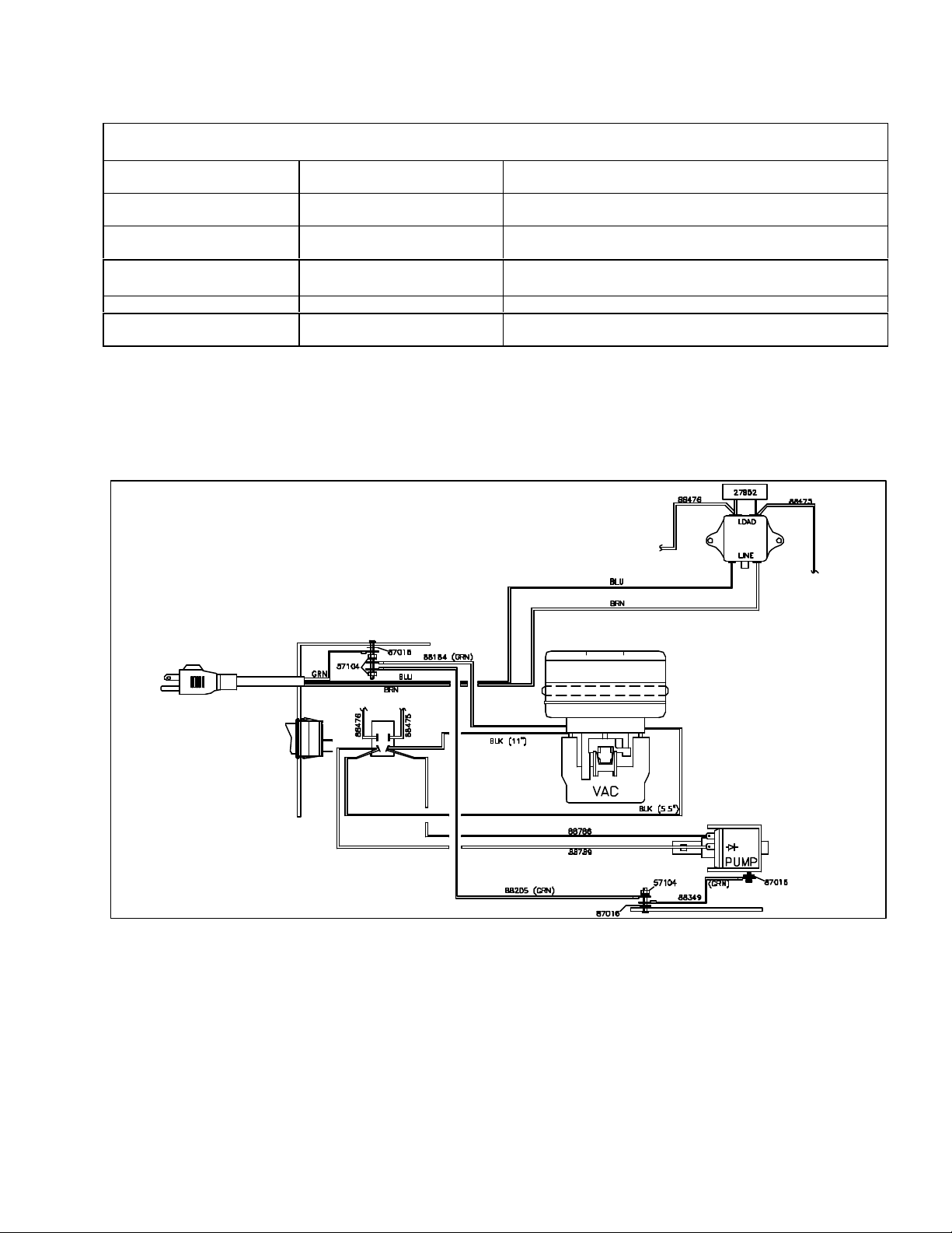
TROUBLESHOOTING
PROBLEM. CAUSE SOLUTION
TROUBLESHOOTING/WIRING DIAGRAM
Little or no solution flow
Loss of vacuum/
Solution recovery
WIRING DIAGRAM
Clogged spray jet on cleaning
tool
Faulty pump
Incorrectly attached solution
hose
Incorrectly attached vac hose
Obstruction in cleaning tool Inspect for and remove any debris.
Recovery tank is not securely
mounted on the solution tank.
Remove and clean jets
Check and replace pump.
(Call Windsor Tech. Services first)
Ensure solution hose coupler is securely attached to the
coupler on the solution tank.
Ensure vac hose is pushed completely onto the recovery
tank inlet.
Tighten latch on back end of the machine.
PRSIF2/PRSDIF2 98902 02/08/03
4-2
Page 12
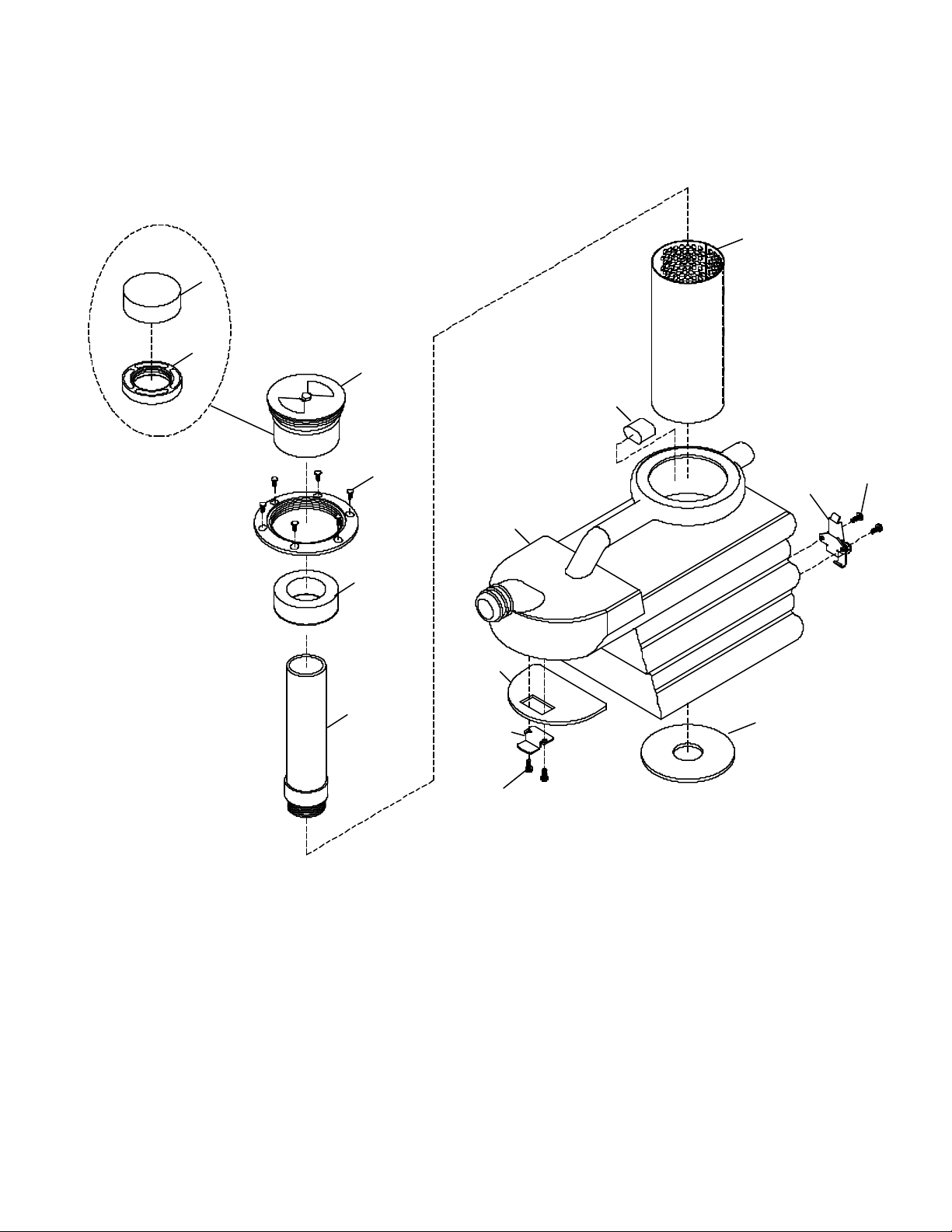
RECOVERY TANK PARTS
5-1
13
14
PARTS INSIDE
PORTAL CAP
10
1
9
2
11
5
8
3
7
4
6
5
12
PRSIF2/PRSDIF2 98902 06/28/03
Page 13

RECOVERY TANK PARTS LIST
REF PART NO. QTY DESCRIPTION
1 05160 1 ASM, ACCESS COVER
2 70546 6 SCR, 8 X ¾ PFHT/S BLK ZINC
3 34391 1 FLOAT ASM SPOTTER WGHT
4 78484 1 TUBE ASM, SPOTTER
5 70683 4 SCR, 10-32 X 3/8 PPHMS SS NP
6 50-501913 1 BRKT, REC/SOL TANK GRIP
7 43-807525 1 GASKET, RECOVERY TANK SEAL
8 75368 1 TANK, RECOVERY SPOTTER DRK BLU
9 43-807578 1 PLUG, HANDLE RECOVERY TANK
10 50-502114 1 PLATE, BACKSPLASH SHIELD
11 46-802541 1 LATCH, TENSION 3.22L
12 35168 1 GASKET, 2.5”ID X 4”OD X 3/8”T
13 14-806573 REF FOAM, AIR FILTER SPOTTER
14 11-800518 REF BUSHING, 3” PVC FLT SHUTOFF
SERIAL NO.
FROM
NOTES:
PRSIF2/PRSDIF2 98902 08/19/04
5-2
Page 14

SOLUTION TANK PARTS
*
*
5-3
PRSIF2/PRSDIF2 98902 02/01/03
Page 15

SOLUTION TANK PARTS LIST
REF PART NO. QTY DESCRIPTION
1 75367 1 TANK, SPOTTER SOL DK GRY
2 40066 3 HOSEBARB, 1/8NPT X 3/8 90D PLASTIC
3 270-11A 1 NIPPLE, 1/8 FPT QD MALE BRASS
4 56032 1 NIPPLE, 1/8 CLOSE
5 20042 5 CLAMP, 3/8 HOSE (D-SLOT)
6 39035 1 HOSE, 3/8” NYLOBRAID X 10”
7 73864 1 STRAINER, 3/8 NPT 60 MESH
8 40067 2 HOSEBARB, 1/8MPT X 3/8 PLASTIC
9 40043 1 HOSEBARD, 3/8MPT X 3/8 90D
10 39233 1 HOSE, 3/8” RUBBER X 17”
11 57104 6 NUT, 10-32 W/STAR WASHER PLTD
12 140446 2 BRKT, PVC FLOJET PUMP L-SHAPE
13 250-78A 1 PUMP, 220/240 50HZ FLOJET
14 39049 1 HOSE, 3/8” RUBBER X 11”
15 50-502111 1 PLATE, LOWER PANEL COVER
16 87016 1 WASHER, #10 LOCK EXT STAR
17 70088 5 SCR, 10-32 X ½ PPHMS SS NP
18 70683 13 SCR, 10-32 X 3/8 PPHMS SS NP
19 50-502108 1 PLATE, VAC MOTOR
20 53802 1 VAC ASM, 230V SPOTTER
21 330-13 1 SWITCH, DPST ROCKER 20A
22 70351 4 SCR, 10-32 X 3/8 HHTR W/STAR
23A 23700 REF CORD ASM, 230V SPOTTER BRIT
23B 23701 REF CORD ASM, 230V SPOTTER EURO
23C 23702 REF CORD ASM, 230V SPOTTER AUSTR
24 73505 1 STRAIN RELIEF, ½ NPT TRUMPET
25 67023 2 RIVET, 1/8OD X 3/8 GRIP
26 46-802542 1 KEEPER, TENSION LATCH
27 70595 1 SCR, 10-32 X 1 PPHMS GRN
28 50-502110 1 PLATE, SWITCH/CORD SPOTTER
29 57040 1 NUT, ½ CONDUIT
30 70363 1 SCR, 10-32 X 3/8 PHTR PLTD
31 27952 1 CAPACITOR ASM, EMI SPOTTER
32 34290 1 FILTER, EMI 250V 6A 1.75MH
33 20103 1 CLAMP, 43/64” NYLON RATCHET *
SERIAL NO.
FROM
NOTES:
PRSIF2/PRSDIF2 98902 02/01/03
5-4
Page 16

LABELS & PARTS LIST
REF PART NO. QTY
1 500009 1
2 500528 2
3 500529 2
4 50776 1
5 500480 1
DESCRIPTION
LABEL, WARNING
LABEL, PRESTO MAIN
LABEL, WINDSOR LOGO 6 X 1.75
LABEL, FOR SAFETY
LABEL, ON/OFF VAC/PUMP
SERIAL NO.
FROM
NOTES:
5-5
PRSIF2/PRSDIF2 98902 12/28/01
Page 17
PRESTO HAND TOOL & PARTS LIST
5-6
REF PART NO. DESCRIPTION
1 41422 HOUSING, HANDTOOL SPOTTER
2 20053 CLAMP, DHT VALVE
3 39593 HOSE ASM, HOSE/CUFF CONNECTOR
4 270-11 NIPPLE, 1/8 FPT QD FEM BRASS
5 44074 JET, ASM W/O RING
6 70268 SCR, 8-32 X1/4 PHST PLTD
7 62918 PLATE, RETAINER W/SCRS
8 54181 MANIFOLD, SPOTTER 3/16
9 34384 FITTING, 1/8MPT X 3/16 COMP
10 84177 VALVE ASM, SPOTTER PLASTIC
39592 SPOTTER HAND TOOL (SHT) Entire assembly as Kit
SERIAL NO.
FROM
NOTES:
2
1
3
10
5
8
7
9
6
4
PRSIF2/PRSDIF2 98902 12/12/02
Page 18

PRESTO CART & PARTS LIST
REF PART NO. DESCRIPTION
1 78310 TUBE, CART HANDLE
2 70010 SCREW, 1/4-20 X 1.5 TAP PLTD.
3 57196 NUT, 1/2 STAR LOCK PUSH-ON
4 57104 NUT, 10-32 HEX W/ STAR WASHER
5 89048 WHEEL
6 57047 NUT, 1/4-20 LOCK
7 27637 BASE, CART PRESTO
8 70088 SCREW, 10-32 X 1/2 PHMS
9 140088 BASKET, 3 BOTTLE
10 18010 CASTER, SWIVEL
SERIAL NO.
FROM
NOTES:
5-7
PRSIF2/PRSDIF2 98902 12/28/01
Page 19

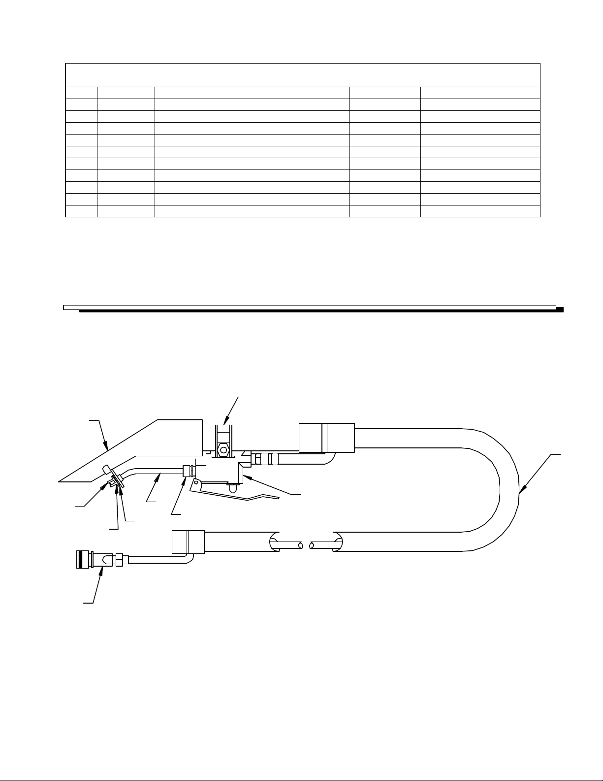
PRESTO DELUXE HAND TOOL ASSEMBLY
2
REF PART NO. DESCRIPTION
1 04007 ADAPTOR, 1/8 MPT X 1/8 FPT BR
2 12509 BRUSH, DDH
3 22026 COUPLER, 1.5 VAC HOSE
4 27677 CUFF, SWIVEL DDH HOSE EXIT
5 27678 CUFF, SWIVEL DDH
6 27685 CONNECTOR, 1/4T COMP X 1/8 MPT
7 31067
8 39463 HOSE, VAC 1 1/2 X 5' DDH
9 78384 HOUSING, DOUBLE VAC, ASM
10 44052 JET, BODY MINI-QUICK W/ SEAL
11 44060 JET, 8002 MINI-QUICK REPLACEMENT
12 51248 LEVER, TRIGGER
13 51249 LOCK, LEVER
14 51250 LEVER, HANDLE
15 270-11 NIPPLE, 1/8 FPT QD FEM BRASS
16 57240 INSERT, 8-32 NUT
17 66031 PIN, ROLL 1/8" X 3/4"L SS
18 70045 SCREW, 8-32 X 1 PPHMS SS
19 70704 SCREW, 6-32 X 7/8 PPHMS SS
20 73776 SPRING, COMP. .08D X .75L X .01W
21 73835R SHIELD, DDH UPHOLSTERY
22 78335 TUBE, 1/4OD X 77.5"
23 84137 VALVE, 1/8 NPT
24 87017 WASHER, #8 FLAT
25 57049 NUT, 6-32 HEX NYLOCK SS
ELBOW, 45° 1/4T X 1/8 NPT
SERIAL NO.
FROM
NOTES:
15
8
22
6
3
4
5
13
20
14
25
19
16
9
12
17
23
21
24
18
1
7
10
11
24
PRSIF2/PRSDIF2 98902 06/28/03
5-8
Page 20

SUGGESTED SPARE PARTS
PART NO. DESCRIPTION
44074 JET ASM W/O-RING
44060 JET, 8002 MINI-QUICK REPLACEMENT
330-13 SWITCH, DPST ROCKER 20A
53802 VAC ASM, 230V SPOTTER
250-78A PUMP, 220/240 50HZ FLOJET
SERIAL NO.
FROM
NOTES:
5-9
PRSIF2/PRSDIF2 98902 06/28/03
Page 21

NOTES
PRSIF2/PRSDIF2 98902 06/28/03
5-10
Page 22

5-11
PRSIF2/PRSDIF2 98902 12/28/01
 Loading...