

Page 1

SUPREME
ULTRA
HIGH
SPEED
BURNISHER
P
1
700120
SERVICE
MANUAL
AND
PARTS
LIST
INSPECTION
Carefully unpack and inspect your ma
chine for shipping damage. Each unit is
operated and thoroughly inspected before
shipment, and any damage is the re
sponsibility of the delivering carrier who
should be notified immediately.
ELECTRICAL
This rotary polisher is designed
to
oper
-
ate on a standard
15
amp,
115
volt,
60
hz,
AC household current. Check that the
voltage shown on the serial number plate
is suitable for the supply available. Volt
-
ages below
105
volts or above
125
volts
could cause damage
to
the motor.
WARNING:
To avoid electric shock do
not expose to rain. Store indoors.
GROUNDING INSTRUCTIONS
To protect the operator from electrical
shock, this machine must be grounded
while in use. The machine is equipped
with an approved, three
-
conductor
power cord and three
-
prong grounding
type plug
to
fit the proper grounding
type receptacle. The
P1700-20
is equip
ped with a
14-3,80
foot power cord.
OPERATION
1.
Plug machine into the power supply
and check that the red indicator light
(located on top of switch housing)
is
on.
2
You will notice three control levers
located at the top of the handle. The
two smaller ones directly beneath
the handle grips control the onloff
switches. From the operator's posi
tion, the longer lever on the right is
used for
adiustina/lockina the handle
in position.'
"
-
3.
With the handle locked in the upright
position, tilt the machine back until
the handle is resting on the floor ex
-
posing the
Hi$h-Flex
drive-pad. Install
the proper high speed buffing pad
using the
centering/locking pad
holder
to
retain pad.
4.
With the pad properly installed, return
machine
to
the upright position.
CAUTION:
To prevent possible dam
age to the pad or pad driver, remove
buffing pad from machine when not
in use.
5.
Adjust front caster: For
thln
pads
turn caster adjusting knob counter
clockwise to lower machine. For
thick pads turn clockwise to raise
machine.
NOTE:
When pad pressure is properly
set, the machine will start instantly.
It too much pressure is
applied, an
overload of motor will exisf cawing
circuit breaker
to
trip.
6.
Pull up on the adjusting lever and
lower the handle to a comfortable
working height. Release adjusting
lever
to
lock
handle
in
place.
NOTE:
A
safety switch mounted
in
the handle
will
not allow machine
to
run until handle is lowered
to
the
operating position.
For best results, the Supreme
High-
Speed Burnisher should be operated
in a straight line - forward and re
-
verse
-
not side
to
side as you would
a
low speed polisher.
The floor polisher is equipped with a
circuit breaker. The action of the cir
cuit breaker is entirely dependent
upon the loading
of
the brush drive
motor and will only trip under exces
-
sive overload conditions. If the circuit
breaker should trip, it can be reset
after
20
seconds by pressing the re
-
set button on the right hand side of
the motor housing.
NOTE:
The operator should correct
the cause
of
overloading before pro
-
ceeding. The most common cause is
an excessively soiled pad which
should be
tu'rned over, cleaned
or
re
-
placed.
SERVICING
A
full service inspection involves the
in
-
spection and testing of all items which
affect operator safety, items which may
require adjustment from time
to
time,
and items subject to wear which may
require replacement in order
to
prevent
a
breakdown.
Motor:
The motor is totally enclosed,
capacitor start, capacitor run with circuit
breaker protection.
All
ball bearings are sealed and have
enough lubricant for the life of the
machine.
Remove motor cover occasionally and
blow dust and lint from motor housing.
Wheels: Periodically remove wheels and
add silicone lubricant
to
axle.
Motor
Removal:
1.
Remove high-flex drive pad
(4)
screws.
2.
Remove brush cover
(6)
screws.
3.
Release tension on belt tension spring.
4.
Remove motor mounting bolts
(3).
Belt Replacement/Adjustment:
1.
Remove high-flex drive pad.
2.
Remove brush cover.
3.
Release tension on
belt
tension spring.
4.
Loosen nuts on motor mounting studs
-
4
or 5 turns.
5.
Install new belt and readjust belt
tension as shown:
The trouble shooting guides on inside
and back cover have been categorized
to
assist you
in
locating and servicing
problems that could occur during the
life of the
High-speed Burnisher.
Page 2
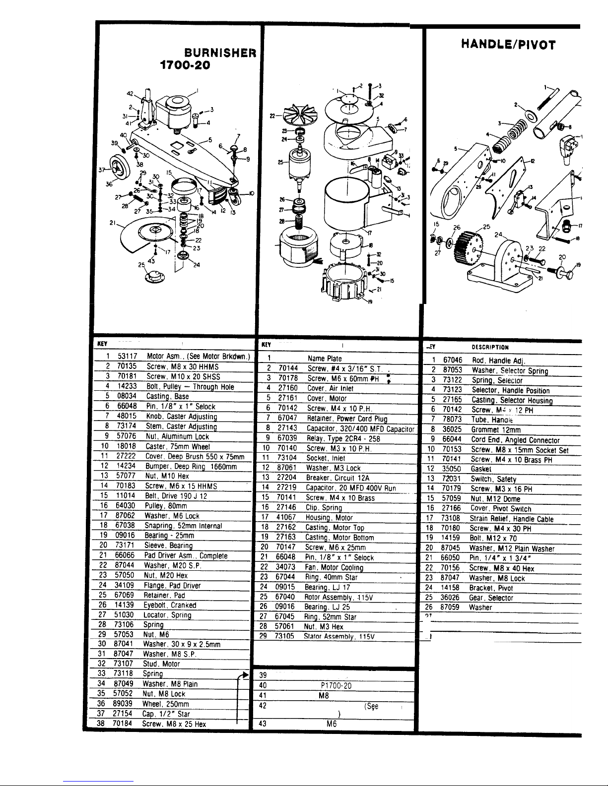
SUPREME ULTRA
HIGH
-
SPEED BURNISHE1
P
d
700-20
:Y
PART NO. DESCRIPTION
MOTOR
ASSEMBLY
P
1
700-20
29
iY
PART NO. DESCRIPTION
~~
87046
Washer, Wave
03025 Axle.
P1700-20
57054
Nut.
M8
66067
Handle Pivot
Asm..
(See Handle
Breakdown
)
70185 Screw,
M6 x 30 PHMS
HANDLEIPIVOT
ASSEMBLY
IY
PART
NO.
OESCRIPTION
'
57060
Nut.
Half Hex
I
87058 Washer.
M4
Flat
I
87057 Washer,
M4
Shakeproof
-
Page 3

Page 4

GENERAL
Usor
sorvltoablo
faults
Red
ligM will not
come on
or
goes
out
when trying
to
start
Red
light on
will not
start
Poor
starl/run
trips circuit
breaker
or
blows
fuses
Machine “wobbles”
in
use
C
AULT
Not
plugged
in.
not
switched on
Faulty plug connections
fuse blown or wrong
fuse fitted
Faulty supply cable
Wrong supply voltage
Handle not
in
operating
position
Handle assembly
not
plugged
into
motor
Circuit breaker tripped
motor overloaded
Wrong supply voltage.
Floor pad
wornlnot
centered.
REMEDY
Plug in and switch on
Open plug and inspect
connections
&
cable re
-
straint - fit a new fuse
Check by substitution
Check name plate.
Lower handle
Plug handle assembly
into motor
Press red button
to
reset
circuit breaker
-
wash
or replace floor pad.
Check name Plate
Check floor pad for uneven
wear
-
center
on
the
drive plate.
WINDSOR
LIMITED
WARRANTY
WINDSOR
warrants
to
the original purchaserluser
for
a
period
of
one
year from date of purchase that this Rotary
Floor
Machine
IS
free
from defects in
workmanship and materials, under normal use and
service. and when operated and maintained in accordance with
Windsor’s service and operating instructions This warranty does
not
apply
to
normal wear items such as electrical cable relays
capacitors. rubber parts and switches During this one year period
Windsor will replace
or
repair defective parts covered b this war
ranty when the machine
IS
delivered either to the fact0 $n;lglewm
Colorado
or
to
an Authorized Windsor Service Center ?ransportation
Costs are
to
be prepald by the original purchaserluser
EXTENDED
WARRANTY
In
addition
to
the above warranty, the following
will
apply
1
In
the event of failure from normal usage during the useful life
Of
the machine of the main
onloff’ switch located in the ma
chine handle switch housing. WINDSOR will replace or repair
such switch free of cost except for labor and transportation
charges which
must
be borne by the original purchaser
2
For a period
of
three years after purchase WINDSOR will. with
-
out charge replace
or
repair any motor that fails as a result of
defects during normal service and usage except for normal
wear items as described above and for transportation charges
to
and from the Windsor factory which must be prepaid by the
original purchaser
This warranty is in lieu of all other warranties. expressed
or
implied.
and releases WINDSOR from all other obligations and liabilities
It
is applicable
only
in
the U S A and Canada, and
IS
extended only
to
the original user purchaser of this product
WINDSOR is
not
responsible for costs
for
repairs performed by
other persons unless they have been specifically authorized in
advance and in writing by WINDSOR This warranty
does
not apply
to
damage from transportation alterations by unauthorized persons
misuse
or
abuse of the equipment use of noncampatible chemicals
or
damage or
loss
of income due to malfunctioning of the product
TROUBLE
SHOOTING
BELT
DRIVE
TRAIN
SYMPTOM
MDtor
runs,
bolt
slip,
nalpoor
drivo,
squeak on
start.
promaturo
bolt
woar
Belt
runs
OH
High
amps,
tripping.
blows
fuses
Noisy
or
“clicking”
drivo
pulley
w
WINDSOR
INDUSTRIES,
INC.,
135
CAULT
Belt too slack
Belt worn or broken
Motor
slide
seized
Polished/greasy drive pulley
Pulleys out
of
alignment
-
belt tension too high
Seized or stiff pulley
bearings
Bearings or housings worn.
TEST
Stall test machine with
drive board glued or screwed
to floor
lnsoection
Remove belt slacken
mounting spring check for
free movement.
Inspection
Check pulley alignment
Turn drive by hand
-
run
motor with belt removed.
InSpectlOn
REMEDY
Adjust
belt tension correctly.
Check pulley alignment
before fitting new belt.
Ensure free movement in
guide
slots
over
lull
length.
Remove grease with solvent
-
emery pulley surface.
Realign pulleys. refit drive
belt.do not over tension.
Replace bearings.
Replace
-
CAUTION
The bearings are shrink
fitted. heat the pulley before
reassembly.
I
!
W.
Stanford
Ave.,
Englewood,
CO
80110
USA
3031762-1800
TWX
910.931-0565
2af
 Loading...