

Windsor L175 Owner's Manual

Contents:
1
Warnings - Product Description
2
4
Wiring Diagrams
5
Motor, Frame, Driver Assembly
6
Cover Assembly
7
Handle Assembly
9
Trouble Shooting
10
Warranty
Operation
/
Maintenance / Service
Record model and serial number located on
data label. Refer to these numbers when calling
Windsor dealer for parts or service.
MODEL
:
SERIAL
NO.
:
PURCHASE
DATE
:
WARNING
OF
A
POTENTIAL INJURY:
This product contains moving parts. To
reduce the risk of injury unplug the
machine before servicing.
Whenever repairs are made ensure electrical
connections are correct and wiring matches
APPROPRIATE
diagram before plugging
machine into an electrical outlet.
CAUTION:
1
.)
See the Owner’s Guide for
complete operating instructions.
2.)
Maintenance
and
repairs must only
be done by qualified personnel.
3.)
Using non-Windsor parts to repair
this machine will void the warranty.
0
80110
USA
303-762-1800*FAX3
98116
Rev.1
512/94

INSPECTION
OPERATION
Please carefully unpack and inspect your machine
for shipping damage. Each unit is operated and thor
oughly inspected before shipment, and any damage is
the responsibility of the delivering carrier who should
be notified immediately.
ELECTRICAL
This rotary polisher is designed to operate on a standard
15
amp,
115
volt,
60
hz,
AC
household curtent. Check that the
voltage shown on the serial number plate is suitable for the
supply available. Voltages below
105
volts or above
125
volts
could cause damage to the motor.
NOTE: 230/250 volt
50
hz
models
are available.
,
GROUNDING INSTRUCTIONS
This appliance must be grounded.
If
it should malfunc
tion or break down, grounding provides a path of least
resistance for electric current to reduce the risk of elec
-
tric shock. This appliance is equipped with a cord hav
ing an equipment-grounding conductor and grounding
plug. The plug must be inserted into an appropriate out
let that is properly installed and grounded in accor
dance with all local codes and ordinances.
WARN
1
NG
:
Improper connection of the equipment-grounding
conductor can result in
a
risk of electric shock.
Check with a qualified electrician or service person
if
you are in doubt as
to
whether the outlet
is
prop
-
erly grounded.
Do
not modify the plug provided
with the appliance
-
if
it will not fit the outlet, have
a proper outlet installed by
a
qualified electrician.
This appliance is for use on a nominal 120-volt circuit,
and has a grounded plug that looks like the plug in
“Fig.
A
below. A temporary adaptor that looks like the adap
-
tor
in
“Fig
.
C“
below
may
be used to connect this plug
to
a
2-pole receptacle as shown in “Fig. B below,
if
a
properly grounded outlet is not available. The tempo
rary adaptor should be used only until a properly
grounded outlet (Fig.
A)
can be installed by a qualified
electrician. The green colored rigid ear, lug,
or
the like
extending from the adaptor must be connected to a per
-
manent ground such as a properly grounded outlet box
cover. Whenever the adaptor
is
used, it must be held
in place by a metal screw.
PROPER GROUNDING CONNECTION
CONNECTION USING
AN
ADAPTOR
GROUNDING
Grounding Pin
\\
I
-
Metal
Screw
Grounded
Outlet
Rg.
A
/
Tab
For Groundina
-
Screw Grounded Outlet
Box
ADAPTOR
-
flg.
B
NOTE: Adaptors
are
not allowed In Canada.
‘6
Fig.
C
CAUTION: For indoor
Use
Only.
To
prevent possible damage to the floor
when using the Brush optlon, use water or other
approved
cleanlng solution while operating.
When using the pad optloln, always keep
the machine moving when In contact with the
floor.
WARNING:
HIGH STARTINQ
TORQUE.
HOLD MACHINE FIRMLY
WITH
BOTH
HANDS.
1
.)
Ensure that the pad driver
or
brush is installed correct
-
ly and in good shape. Install or change pad
if
necessary
(See Page 3
for
detall
of
Installation).
2.)
Plug the machine into a wall outlet
as
described in the
grounding instructions.
3.)
Lower the handle
by
unlocking the adjustment handle
and moving the handle into position.
Relock the handle
when it is in a comfortable position.
4.)
Check to be sure the pad driver or brush is installed
before starting.
5.)
With the switch lock@) rotated forward, squeeze
one
of the switch levers, turning the machine on. (These levers
can be operated independently
of
each other)
6.)
To
stop the machine, release the switch lever
and
switch lock.
NOTE
The machine is equipped with a circuit breaker
to
protect the motor in the event
an
overload condition
occurs. The circuit breaker is located
at
the bottom
of
the
switch housing. Push the reset button to restart the ma
-
chine.
If
the breaker trips again, correct the cause
of
over
-
loading before proceeding.
7.)
Do
not let machine rest on pad. When finished with the
machine for the day return handle to the storage position.
Be sure to leave machine in a
safe
place where there is no
risk
of
being tipped over.
CONTROLS
Page
2
R0v.l
y2/94
L175”
.. . .
I
1
NOTE:
In
the
following
instructions
all
letter
will
be
shown
in
the
up-
DAILY
MAINTENANCE:
(At
the
end
of
each
working
day):
1.
Inspect power cord for wear.
To
prevent
electrical
shock replace cords with frayed or cracked insulation
MAINTENANCE INSTRUCTIONS FOR THE
L175
SERIES
OF FLOOR SCRUBBERS
immediately.
Place machine
in
the storage position.
Check pad condition. Change
if
soiled or torn,
2.
3.
WARNING:
Remove machine power cord from electrical
source before making any adjustments or repairs to the
machine.
Only qualified maintenance personnel are
to
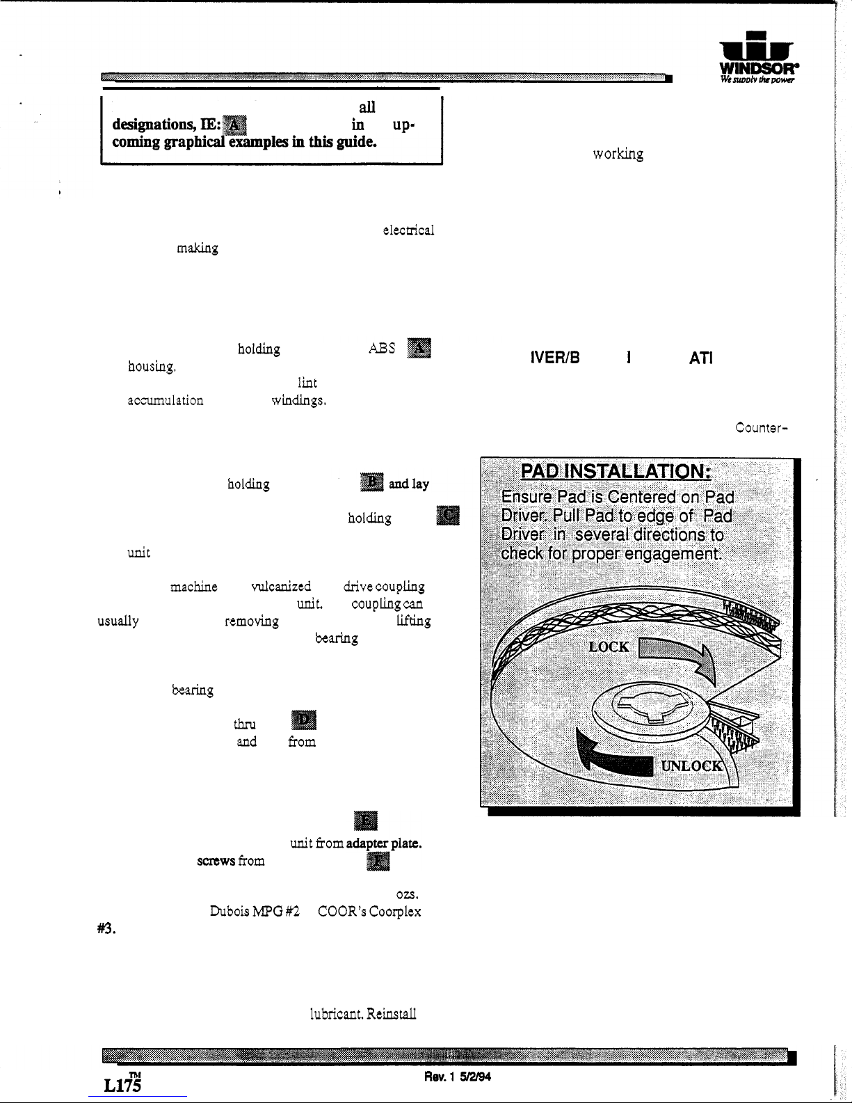
PADS:
perform repairs.
MOTOR
Only
standard
1/2
inch thick
pads
suitable for low
speed
burnishing
are recommended.
PAD
D
R
IV
ER/B
R
US
H I NSTA
LL
AT1 0 N
:
1.
2.
1.
2.
Remove
(4)
screws holding motor cover to
ABS
housing.
Use compressed
air
to remove lint
and
dust
accumulation from motor windings.
Lay
machine back on
the
ground, exposing
the
underside.
Place pad driver or
brush
on
the
motor lug and rotate
clockwise
until
engaged.
To
remove,
turn
Counter-
MOTOR-GEAR UNIT ASSEMBLY
1.
2.
Remove
(4)
bolts holding handle bracket
aside. Lift
off
plastic motor shroud.
Tip machine back
and
remove
(4)
bolts holding brush
cover and gear unit to
chassis.
Lift
out motor and gear
unit assembly.
NOTE:
The machine has a vulcanized steel drive coupling
located between
the
motor
and
gear
unit.
The coupling
can
usually be replaced by removing the motor cover and lifting
out the armature.
If
the
lower
armature
bearing
remains
in
gear unit adapter plate, it
will
have
to
be
removed from the
gear
box
to
access the bearing
for
removal.
3.
Remove
(4)
motor
thru
bolts and
lift
off
motor
cover. Remove armature
and
field from gear unit adapter
plate.
GEAR UNIT
1.
2.
3.
NOTE:
The
maximum
capacity
of
the
gear
unit
is
10
ozs.
Use
gearbox grease Dubois
MPG
#2
or COOR’s Coorplex
#3.
Remove
(6)
screws
from
adapter plate.
Use
pry bars to seperate gear unit fiom
Remove
(6)
saws
fnnn
gear unit cover.
Remove cover. Repair
as
needed.
WHEELS
1.
Remove wheels every 2 to 3 moths. Clean axle an
apply
a
small
amount
of
silicone lubricant. Reinstall
wheels.
clockwise.
NOTES:
L1%
Rev.1
5/2/94
3
 Loading...