

Page 1

L22AF
(OBS)
Page
1
of
20
CONTENTS:
2
3
4
5
6
8
9
10
11
12
13
14
15
16
17
18
19
22
Safety Instructions
Battery Information
Control Panel
Layout
Drive Controls I Operation
Maintenance
Hood Assembly
Shroud Assembly
Service
I
Adjustments
Lvi
Linkage
Deck
Lift
Mechanism
Chassis
Drive Assembly
Drive Control Assembly
Electrical Controls
Wiring Diagram
(F22)
Wiring Diagram
(F22T)
Trouble Shooting
Warranty
-
MODELS:
F22,
F22T
~
981
77
Rev.
716194
FILTRON~C'
Page 2

-
IMPORTANT SAFETY INSTRUCTIONS
When using battery powered machines, basic precautions should always be followed, including
the
following:
READ ALL INSTRUCTIONS BEFORE USING MACHINE
Operate from the rear of the machine only.
Use caution when operating the machine on a ramp or incline.
Do
not turn the machine, or leave it unattended, on a ramp or incline.
~~ ~ ~~ ~~
Machine can cause an explosion when operated near flammable vapors
or materials.
Store machine inside. Keep the electrical components of the machine dry.
Lead acid batteries have a number of inherent dangers, carefully read the
instructions and warnings which accompany the batteries and battery charger.
REMEMBER:
The batteries generate gasses which can ignite. Always
charge in a well ventilated area. Keep sparks and flames away from the
batteries.
Do
not smoke around the batteries. Avoid skin contact with the acid
contained in the batteries. Always wear eye protection and protective clothing
when working on or near batteries. Never allow metal objects to lay across
battery tops.
~ ~~ ~~
All
maintenance and repairs must be done by qualified personnel only.
Maintain adjustments on machine as specified in service manual.
Make sure all warning and caution labels are legible and properly
attached to the machine.
SAVE
THESE
INSTRUCTIONS
Record the model and serial number on the blue data label located at the rear of the machine
.
These numbers are used when calling upon the Windsor dealer for parts and service.
MODEL SERIAL
NO.
PURCHASE
DATE
nv
damaaes
which
2
Rev.7
7/6/94
FILTRONIC
Page 3
L22AF
(OBS)
Page 3 of
20
Battery Maintenance:
When cleaning batteries use a solution
of
baking
soda and water.
(Do
not allow cleaning fluid to
enter inside battery cells.)
Keep a proper electrolyte level in battery cells.
Wipe down the battery tops at least once a
week.
If
a
cell
should accidently overflow, clean
immediately.
Test battery condition with a hydrometer at least
once a week.
Ensure that all connections are tight and that
all
corrosion
is
removed.
Every
4
to
6
months remove batteries from the
machine and clean the battery compartment.
Spare Parts and Accessories:
021
00
Hydrometer
02101
Battery
Post
Cleaner
02143
Battery,
12V
DC,
20
Amp,
185
Amp Hour
02104
Charger,
36V
DC 20 Amp, Auto Shut-Off
(115v)
02141
Charger,
36V
DC
20
Amp, Auto Shut-Off
(1
OOV
50/60
Hz)
02142
Charger,
36V
DC
20
Amp, Auto Shut-Off
(230V
60
Ht)
02155
Charger,
36V
DC
20
Amp, Auto Shut-Off
(250V
50
Hz)
021
63
Charger,
36V
DC
20 Amp, Auto Shut-Off
(230V
50
Hz)
231
25 Cable,
12
"
Red
78231
Battery Tray
FILTRON~
Rev.1
7W
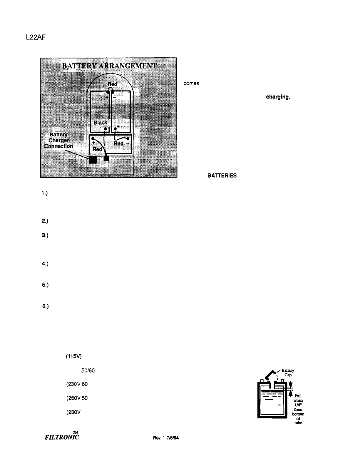
Battery Charging Procedure:
Charge the batteries once the amber charge
level
light
comes on.
The
amber light indicates that there is
about
20%
charge
left
in the batteries.
Do
not let the
batterles completely drain before
charglng.
Avoid
charging the batteries before the amber light comes
on.
The
machine will run for hours
on
fully charged,
well
maintained batteries.
DO NOT SMOKE, HAVE OPEN FLAMES,
OR
SPARKS NEAR BATTERIES
AT
ANY TIME.
WARNING:
WEAR EYE PROTECTION AND PROTECTIVE
CLOTHING WHEN WORKING
WITH
BATTERIES.
CHARGE
BAlTERlES IN A WELL VENTILATED
AREA WITH DECK DOWN AND COVER OPEN.
1
.)
Use
a
36
volt, 20 amp maximum output, D.C.
charger which turns itself
off,
when the batteries are
fully charged. The charger must have a connector
that matches the machines battery connection.
2.)
Read the instructions and warnings provided by
the battery charger manufacturer.
3.)
Set the charger
in a well
ventilated area on a lev
-
el
surface. Make sure cords will easily reach outlets
on both machine and wall.
4.)
Connect
charger to
D.C.
outlet on machine
first.
5.)
Connect the A.C. power cord to properly
grounded wall socket.
NEVER MAKE THE A.C.
CONNECTION FIRST, HAZARDOUS SPARKS MAY
RESULT.
6.)
After the batteries are completely charged discon
-
nect the charger from the A.C. wall socket.
7.)
Once the charger is disconnected from the A.C.
wall socket it is safe to disconnect the charger from
the machine.
8.)
When the batteries
are fully charged, check the
electrolyte level by removing
the caps on top of the
batteries.
If
necessary
fill
the
cells with distilled water as
shown in the diagram to the
-
-
right. Be careful not to overfill
cells.
Nbe
3
Page 4

L22AF
(OBS)
CONTROL
PANEL
I
I
n
IV
I
I
i
L.
70
Amp 3AmD r8AmD
Main power switch. Turns power on
and
off
to machine.
Deck lift switch. Tactile membrane
switch raises or lowers deck when
pressed.
Deck raised, amber indicator light.
Deck lowered, green indicator light.
Polisher running, green indicator
light. Light comes on when machine
is running and the pad is making
proper contact with floor.
[
1
J
I
Rev.$
71#’94
6.)
Battery charge drained, red light.
Operator has less than ten minutes to
return machine to charger. Once
batteries are completely drained the
red light flashes, polisher motor quits
running, and the deck automatically
raises.
7.)
Battery charge level low, amber
indicator light. Operator should return
machine
to
charger.
8.)
Battery charge level, green indicator
lights. Each light represents
1/4
charge, lights go out as the batteries
drain.
9.)
Danger, no pad, red flashing light.
If
someone tries to operate the machine
without the pad in place the deck will
automatically raise and the machine will
turn
off.
Turn main switch
off
and install
pad. Machine can be turned back on
once
pad
is
properly installed.
10.)
Brush wear, red indicator light.
Worn carbon motor brushes need to be
replaced before damage to motor
occurs.(See page
16
Item
20)
11
.)
Pad driver bar, starts pad driver when
squeezed to main handle, stops pad
driver when released.
12.)
Main handle.
13.)
Hour meter.
14.)
70
amp magnetic circuit breaker,
protects pad driver motor.
To
reset turn
to
“ON”
position.
15.)
3
amp thermal circuit breaker,
protects lift mechanism. Press to reset.
8
amp
F22T
Ty
FILTRONIC
Page 5
L22AF
(OBS)
F22T
DRIVE
CONTROLS
Page
5
of
20
1
.)
The speed the machine will travel is
regulated by the knob located on the
controls which are found on the main
handle.
Turn
the knob
to
the
right
to
increase the speed
of
the machine.
2.)
Squeezing one or both
of
the control
levers will propel the machine forward
at the selected speed.
Releasing
both
control levers
will
stop
the machine.
3.)
4.)
Pressing forward on
the
levers moves
the machine backwards at the selected
speed.
Before starting the work period:
1
.)
2.)
Close the cover. is fully raised
4.)
Lower or raise deck by pressing deck
lift switch. On the
F22
models a green
light indicates position to begin
polishing. Amber light indicates deck
Disconnect the battery charger.
(See battery charging procedure)
3.)
Raise the deck. (Turn on the main
power switch and press the deck
lift switch.)
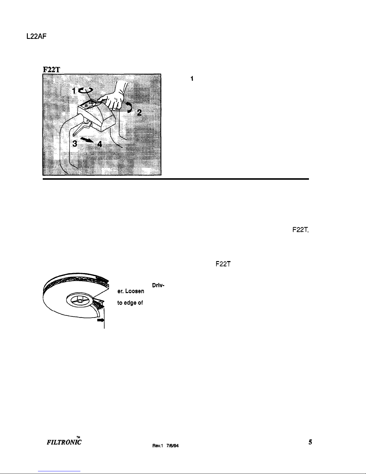
4.)
Turn or install a new buffing pad as
needed.
Ensure
Pad
is
Cen
-
tered
on
Pad
Drlv-
er.Loosen
Pad
Lock
and
pull
Pad
toedgeof
Pad
Driver
in
several
directions.
-i
5.)
Check wheels and other pivot points
for proper lubrication.
Operating the machine:
1
.)
If
using a machine which was already
set up, check to make sure the pad is
properly installed..
Adjust the operating control handle to
a comfortable position using the
handle lock lever.
2.)
3.)
FILTRONI?
Turn on the main power switch.
5.)
All
the machines, except for the F22T,
are controlled by squeezing the
thin pad driver bar and main handle
together.
The
F22T
drive controls are shown
above.
Caution:
To prevent possible
damage to the floor surface, always
keep the machine moving while the
pad is spinning.
The
F22
pad pressure will adjust automatically
to compensate for irregularities in the floor. pad
thickness, aggressiveness, and load. The
mo
-
tor amp draw is monitored causing the front
deck to be raised and lowered.
6.)
When the drive handle is released the
deck will automatically raise and the
motor will turn
off.
7.)
The operator can continue polishing
until all four green battery charge level
indicator lights
go
out.
Return the machine to the battery
charger when the amber charge level
light comes on.
5
8.)
Rev.1
7M4
Page 6

L22AF
(OBS)
Page 6 of
20
F22
MODELS
FILTER CARTRIDGE
The filter (part no. 3421 2)
is
accessed using
the latch at the front of the filter
cover.
Periodically wash the filter out.
BE
SURE
THE FILTER
HAS
COMPLETELY DRIED
BEFORE USING.
FELT DUST CONTROL SKIRT
Replace skirt (part no. 73520) when exces
sively soiled, worn, torn, or damaged in any
way that allows dust to escape.
Located inside the shroud the dust control
skirt is easily replaced. Each slot
on
the skirt
slips onto a tee nut inside the shroud.
ph
b150
ACTUATOR SPRING
To ensure pad pressure consistency, the dis
-
tance between the bottom of the cap spring
(p/n
27430)
and the flange on the actuator
pivot
(p/n 66150) should be 2.125 (see
above).
70424
\
pn
140032
LIFT LINKAGE
To ensure that the pad
is
at the proper height
when in the
“ready” position, the distance
between the edge of the safety switch brack
-
et (p/n 140032) and the end
of
the plunger
assembly
(see
above) must be 1.65”.
Weeklv
Maintenaace:
1.)
Use a hvdrometer to check the
conditioi of each battery cell.
Check battery cable clamps. Ensure
clamps are tight on battery terminals.
Clean tops of batteries with a wet
cloth and a solution of water and
baking soda. Wipe battery tops dry
after cleaning.
Check pad lock for looseness
or
damage.
Check filter and filter seals. Air flow
should be
unobstructed through filter.
Ensure that the chain, on the
F22T
model, and the pivot points and
casters, on all models, are properly
lubricated.
Tighten any loose screws or nuts.
At the end
of
each
work
period:
1
.)
Wipe down the exterior
of
the
machine.
2.) Vacuum out the filter cartridge.
3.)
Lower the deck.
4.)
Open the cover.
5.) Charge the batteries.
(See battery charging procedure
on page
3).
4to6Mo nth inten-
1
.)
Remove batteries - clean battery tray
-.
and battery compartment.
Clean battery cable clamps and
battery terminals.
Check the drive chain tension on the
F22T. Tighten, clean and lubricate
if necessary.
Check the carbon motor brushes in
the pad driver motor.
(#17 on page
12)
Use a vacuum to remove lint or dust
build
-
up from motor windings.
6
Rev.1
7/6/94
FILTRONI;
Page 7

L22AF
(OBS)
Lubrication;
The following symbols found throughout
the manual indicate items requiring
lubrication:
Apply grease
Use spray lubricant.
Use
anti-seize when repairing.
4
Permanent (Red) Thread Lock
reaker 3
Amp
471
Z
Wlrcuit 70
Am0
1491
7
4"
Polvurethane Swivel 18427
rx15 23izfi
23122
ntrol 34212
FlLTqpNlC Filter 35117
Flter.
Cartridae Dust
Co
I
Filter 35131
Holder. Centerlock
411a
Circuit Board. Contro
I
27035
Pad Driver 66182
671
66
Switch. Main
Rotary
72051
125VDC
SP
NC roller 72053
72088
72-
7-
8-
Cable
As-
27" 231
26
le
Asm..
4Ga
blk
x 37"
125VDC
SPST
N.O.
FILTRON~
NOTES:
Rev.1
7/8/94
7
Page 8

L22AF
(OBS)
HOOD
ASSEMBLY
F22, F22T
Page
8
of
20
12
*c
11
PARTS
LIST:
8
N
FILTRONIC
Page 9

L22AF
(OBS)
Page
9
of
20
2
4
See
page
12
inside
of
the
shroud
assembly
i
i
i
i
i
SHROUD
1
ASSEMBLY
1
.21
\
Hem
17
*NOTE:
Item
17
should
extend
3/8'
below
item
12.
N
FILTRONIC
Rev.1
7/8/94
9
Page 10

L22AF (OBS)
Page
10
of
20
ACTUATOR REMOVAL
1.)
Switch
on
main switch and lower buffing
head to floor. Switch
off
main switch.
2.)
Remove main cover and batteries.
3.)
Lay machine
on
left
side.
4.)
Remove actuator connecting
lift
link
##42
on
page
11.
5.)
Disconnect motor
leads.
,
6.)
Remove
(4)
bolts holding actuatorbracket
to frame and
lift
out actuator.
Testing Actuator
Barrel
’Iz.avel:
1.)
Donot allow the barrel
to
rotateorthe
1/2”-9/16” (1,25 to
1,4
cm) adjustment will
be
lost).
2.)
Connect white
wire
to
the
(+)
positive post and
the black
wire
to the
(-)
negative post of the
36VDC power supply to retract
the
barrel to the
lower limit.
3.)
Black
wire
to
the
(+)
positive post and the
white wire
to
the
(-)
negative
post
of the 36VDC
power supply
to
extend the barrel
to
the upper lim-
it.
4.)
Reverse the
wires
to
retract
the
barrel electrical
-
ly. the actuator
is
now ready for assembly and
installation.
LIMIT SWITCH
SETTINGS
Lower
Adjustment
1.)
Connect the white wire
to
the (-)negative
post
of
a 36VDC power supply and the black
wire
to the
(+)
positive post.
This
will
retract or
close the actuator barrel. Maintain the connection
until
the
limit switch shuts
the
power
off.
2.)
Disconnect both wires
from
the power supply.
Set
“A”
(barrel
to
frame
gap) at between
1/2
and
9/16
of
an
inch
(1,25
to
1,4
cm) rotating by
hand.
10
Rw.1
7m
Upper Adjustment
1.)
Hold Barrel
With
Hand
power supply, white wire to the
(+)
positive post
and the black wire
to
the
(-)
negative post.
This
will extend or open
the
actuator barrel.
Reverse the wire connections
to
the 36VDC
Do
not allow barrel to rotate.
2.)
Extend actuator barrel electrically
until
it
stops. Ensure
“A”
is
between 3 3/4 and 3
7/8
in
-
ches (95 to 9,9
cm)
on
all
models.
3.)
If
the
dimension is incorrect, disconnect from
the power supply and set the switch cam adjust
-
ment.
Switch
Cam Adjustment
1.)
Remove the two cam switch cover screws
(TOM
T15) and remove cam
switch
cover.
2.)
Loosen the two cam lock screws
(TORX
“20)
on
the cams.
CAUTION:
Do
not
allow
retract
cam
to
rotate.
3.)
If
the
“A”
dimension
is
incorrect, turning the
cam clockwise will INCREASE
“A,
counter-
clockwise
will
DECRBASE
“A”.
4.)
Tighten the two cam lock screws and cycle the
actuator.
Do
Not Allow The Barrel
To
Row.
Check the extended
“A”
dimension.
If
it is cor
-
rect,
replace
the cover with screws.
If
not repeat
3
above.
ru
FILTRONIC
Page 11

L22AF
(OBS)
Page
1 1
of
20
LIFT
LINKAGE
10
s/-
NOTE:
When the
actuator
continues
Wg
beyond
the
set
limits
use
page
10
to
adjust
or
replace
switches.
KEY
PART
NO.
DESCRIPTION
1
70015 Screw, 114-20 x 314 HHMS
2 70242 Screw, 4
-
40 x 114 PHMS
3 27457 Cord Assembly, Cover Pin
4 66092 Pin, Hair Spring Cotter
5
66149 Pivot, Cover
6 14725 Bushing, Cover Pivot
7 87025 Washer, 114 Star
8 70020 Screw,
114-20 x 112 HHMS
9 14704 Bracket, Deck Linkage
(Left)
10 87013 Washer, 114
ID
x 518
OD
Flat
11 66201 Pivot Asm,
F22T
12 14x8 Bushina. Flame 112 x 314 OD
13 14593 Bushina, Deck Linkaae
14
51147 Linkatre, Deck Lift
15 51151
Linkaae, Deck
Guide
Adi
lR
16 14705 Bracket, Deck Linkaae (Mid)
17
14706 Bracket, Scrub Deck Linkaae
(R)
18 57105 Nut, 1/4-20 Hex wl Star washer
19 571
63
Nut. 4-40 Hex wl Star washer
20
73456 Spacer, Plunaer Switch
21
70245
Screw. 4-40 x 314 PHMS
22 72053 Switch.
125VDC SPST NC
23 140032 Bracket,
Ext.
Microswitch Mntg. (Both:
24 67286 SnaD Rina, 5/16
11
FILTRONIC
Rev.1
7W
Page 12

L22AF
(OBS)
DECK
LIFT
MECHANISM
19-6
69-20
-l
I
Permanent
(Red)
Thread Loeking
adhive
2
For
the
Assemblies
see
pg.
9
Page
12
of
20
12
Rev.1
718/94
TM
FILTRONIC
Page 13

L22AF
(OBS)
F22T
See
Page
#
15
Page
13
of
20
CHASSIS
sea
page
14
of
thls
gulde.
'ARTS
LIST:
'./'
FILTRONI?
Rev.1
716194
13
Page 14

L22AF
(OBS)
DRIVE
ASSEMBLY
PARTS
LIST:
Page
14
of
20
Plate, Motor Spacer
Screw, 1/4
-
20 x 314
HHCS
Washer, 1/4 Lock
Ext
Star
SS
Washer 1/4
ID x 7/8 OD
SS
1”:”
Plate
,,D
Pro el Motor
I
70015
87025
870
13
14
Rev.1 7l6tW
lM
FILTRONIC
Page 15

L22AF
(OBS)
Page
15
of
20
F22T
DRIVE
CONTROL
ASSEMBLY
Adjustment
of
potentiometers
for
drive control
1.
2.
Turn the
speed
potentiometer
(U)
fully
clockwise.
(Max.
speed)
Loosen
the set
screw
(el)
and
adjust
the
direction
potentiometer
(T)
to center
of
travel.
Turn the
main
power
switch
on.
if the
machine
moves, adjust the direction potentiometer
until
movement
stops.
Tighten
the
set
screw
(#21)
3.
4.
5.
TM
15
FILTRONIC
Rev.1
7/6/04
Page 16

L22AF
(OBS)
Page
16
of
20
ELECTRICAL CONTROLS
NOTE:
This
Contrdler
needs
to
be
seperated
horn
the
frame
NOTE
When
wlrlng,
keep
wlnr
clear
of
shunt.
17
NOTE:
Apply
blue
lo*ite
to
internal
threads
of
item
62
on
bolh
end&
. _ .
. .
-
-
.. . . . .
__
5
24
'ARTS
LISF
.6
Rw.2
711
2/94
FILTRONI~
Page 17

WIRING
DIAGRAM
(F22)
CONTROL PANEL
0
000000
mp
88866
CHARGER
I
---
--
CONNECTION
88861
ASM
BLK
88665
n
’AD MOTOR
CIRCUIT
BREAKER
8868(
!ED
__
88670
BATTERIES
GROUND
POST
BLK 23127
CI
4
BLK
88678
1
4CTUATOR
BREAKER INDICATOR
BRUSH WEAR
n
BLK 88963
DEAD-MAN
SWITCH
ELK 88598
88594
ASM
MOLEX
I
BLK
FAsM
I
88958
88668
ELK
88957
ACTUATOR
I
MICRO
SWITCH
I
BL
K
88677
ELK 88859 88669
I-
h)
h)
R
n
0
m
cn
W
Page 18

L22AF
(OBS)
Page
18
of
20
I
FILTRONIC
Rev.
1
7/6rs4
Page 19

L22AF
(OBS)
Page
19
of
20
Troubleshooting
Chart
Condition Corrective
Action
No
Power
To
Mshb
Poor Cable Connection
Faulty micro switch
Faulty main power switch
Faulty
control board
Blown
fuse
Circuit breaker has tripped
Faulty drive handle
switch
Faulty relay
-
Carbon motor brushes
need to be replaced
-
lmhaslw
Circuit breaker has tripped
Loose
actuator conneotions
Faulty actuator
circuit
breaker
or actuator
Faulty control panel
Faulty control board
Deck stays on floor after motor after motor
stops
Deck height fluctuates excessively
FILTRONIC
Clean battery cable
clamps
of any corrosion and tighten test
voltage
at
points A
to
B
should
be
from
34
to
38
VDC.
Test
voltage
at
points C to B should
be
from
34
to
38
VDC.
If
there is no voltage check switch for continuity. Adjust or replace
as
needed
With
the main power switch turned on, test voltage at points B to
D
should be from
34
to
38
VDC.
If
there is no voltage remove
leads and check switch for
Continuity. Replace
if
necessary
Test
voltage at
L6
to
K7
should be from
34
to
38
VDC.
If
the
voltage is
good
at
L6
to
K7
but the machine still won't
respond,
all the tests
above
have been done, replace
the
control board.
Replace
fuse
Reset circuit breaker.
(N)
Unplug connector coming from main handle assembly. Squeeze
handle and test for continuity at handle end of connector
E.
Adjust or replace switch
as
needed
.
See
page
13
&
15
for
exploded
view of switch cover
(F22)
and drive control assemblies
F22T.
With main power on, pad
in
operating position
and
drive handle
squeezed:
Test
voltage
at
points
F
to
Q
and
F
to
B
should
be
from
34
to
38
VDC. When
the
relay
Is
working
it
should make a
clicking noise
as
the drive handle
is
squeezed. Replace relay
if
the
test
voltages measure properly and
the
pad
motor still does
not run.
If
the test voltages are not
34
to
38V DC, check wiring
and connections at
points F,
Q,
D and
B.
When the brush wear indicator light comes
on
it
is
necessary
to
put a new
set
of
carbon
motor brushes
in.
Caution:
Continuing
to
run the machine
until the brushes wear away completely
will cause motor damage.
Reset
circuit breaker
(M)
Check connections
J1L
J2
and
K3 & K4
on control board
along
with all other connections to actuator.
With
the
main power switch turned on
and
the
pad
upldown
switch depressed, test
voltage
at
K4
to
K3
should
be from
34
to
38
VDC.
If
the voltage is
good
at
K4
to W but the actuator
still
is not operating it will need to be repaired or replaced.
Unplug
the
connector at J on the control board. Test J (coming
from control panel) for continuity when pad switch is pressed.
Replace control panel
if
necessary.
Test voltage
at
L6
to
K7
should be from
34
to
38
VDC.
If
the
voltage
is
good
at
L6
to
K7
but
the
lift mechanism
still
won't
respond,
all
the
tests above have been done, replace the
control
board.
Check for worn out pad.
Check for worn
out
pad.
Rev.1
7m4
19
Page 20

L22AF
(OBS)
Page
20
of
20
Troubleshooting
Chart
(cont.)
Condition Corrective Actlon
-
-
Control board stuck in the
self check mode
When the main power is turned on within
3
seconds of the time
that the battery charger plug is removed the control board initiates
a self diagnostic program. To cancel the self diagnostic program
check, simply
turn
off
the main power
switch
for 3 seconds and
turn it back on.
If
the problem persists, turn
Ow
the main
switch
and
remove the 3 amp fuse for 5 seconds. Replace the fuse and turn
on the main switch.
-
Circuit Breaker tripped
Loose connections
Faulty micro switch
Faulty potentiometer
Faulty drive control board
Faulty motor
20
Reset
circuit breaker
(W).
Check
all
connections in propel motor drcuit especially
at
P,Q,R,
V and
X.
With the batteries disconnected, disconnect the wire leads to the
micro switch, at
V, and test for continuity. When the
control
levers
are squeezed the micro switch
is
engaged. There
should
be a
slight clicking sound when the switch is engaged.
Adjust
or
replace
as
necessary.
With the drive motor disconnected at
Q
or
X
test
the
output
voltage
to the drive motor. THe output voltage
at
Q
or X should vary
from
0
to
24
volts
as
the potentiometer U on the controls
is
adjusted and the control levers are squeezed. Resistance
of
the
potentiometen
can
be
tested at
the
green
and
black
leads
found
at
the molex connector at
R.
The resistance should vary from
0-
to
2.2
kilo ohms
as
the potentiometer U on the controls
is
adjusted
with the control levers
squeezed. If these fail, the potentiometers
will both
need
to
be
replaced.
Test
voltage at P should be from
34
to
38
VDC.
If
the voltage at
P
is
good
but
the propel motor won't respond, and all the tests
above have
boen done, replace the drive control
board.
Squeeze the control Ievem,
adjust
the potentiometer
U,
and test
the voltage at
X
or
Q.
When the output voltage at
X
or
Q
varies
from
0
to
24
volts but the motor does not respond, and all the tests
above have been done, replace the motor.
Rev.1
7/8/94
 Loading...