

Page 1

CARPET EXTRACTOR
MODEL POWER SOURCE
EXP 115V ELECTRIC
EXPJ 100V ELECTRIC
U
Read these instructions before using the machine
98363 10/19/02
Page 2

MACHINE DATALOG
y
TABLE OF CONTENTS
MODEL-
DATE OF PURCHASE-
SERIAL NUMBER-
SALES REPERESENTIVE-
DISTRIBUTOR NAME-
OPERATIONS GUIDE NUMBER – 98363
©Copyright 1996 Windsor Industries, Printed in U.S.A.
Cover Sheet......................................................... 1
Data Log / Table of Contents............................... 2
Information in this guide ...................................... 3
Safety................................................................... 4
Hazard Intensity Level ......................................... 5
Operations ........................................................... 6
Option Controls.................................................... 7
Operating Instructions ......................................... 8
Maintenance ........................................................ 9
Maintenance Cont................................................ 10
Troubleshooting ................................................... 11
Wiring Diagram .................................................... 12
Service Schedule................................................. 13
Vac, Solution Tank, Control Panel Assembl
...... 14
Vac, Solution Tank, Control Panel Parts List .......15
Brush, Brush Motor, Frame Assembly .................16
Brush, Brush Motor, Frame Assembly
Parts List ..............................................................17
Pump Assembly ...................................................18
Pump Assembly Parts List ...................................19
Solution Lever, Main Handle Assembly ...............20
Solution Lever, Main Handle Assembly
Parts List ..............................................................21
Recovery Tank Assembly.....................................22
Recovery Tank Assembly Parts List ....................23
Solution Plumbing Spray Jet Assembly ...............24
Solution Plumbing Spray Jet Assembly
Parts List ..............................................................25
Spare Parts and Accessories ...............................26
Warranty...............................................................27
2
EXP 98363 10/19/02
Page 3

INFORMATION IN THIS GUIDE
This Owner’s Guide contains valuable information
about the operation, maintenance, service and part
numbers for repairs of your Windsor machine.
Please read this introductory page thoroughly to
become familiar with the contents of the owner’s
guide, making the information you are looking for
easier to locate.
The owner’s guide consists of multiple sections of
reference information, and the remainder contains
part information for ordering parts for the machine.
At the top of each page is the name of the particular
section. This way you can quickly locate each
section more easily.
REFERENCE SECTIONS
The reference information sections of this guide are
as follows; General Information, Operation,
Maintenance.
GENERAL INFORMATION
This section of the guide contains safety
precautions. The Safety Precau tio ns are an
overview of the safety measures to be observed
when operating and maintaining the machine.
PART SECTIONS
To easily locate the part needed, please refer to The
Table of Contents for component locations to find
the general area where the part is located. Use the
information to quickly locate the correct component.
The remaining sections of the guide contain part
number information for ordering repair parts for the
machine. The guide contains part number
information on every machine model available.
Therefore there will be part num ber inf orm ation in
your guide which you will not need to refer to when
placing an order.
ORDERING REPAIR PARTS
If you are in need of technical assistance contact
your WINDSOR Distributor or Service Center for
further assistance. Once you have located a part to
order, call your local WINDSOR distributor. Make
sure to have the machine’s serial number and your
Owner’s Guide with you to aid in ordering the correct
component(s).
NOTES:
OPERATION
The Operation section of the guide contains the
information needed to operate the machine. There is
a complete list of instruments and controls on the
machine, an overview of mac hine oper at io n, and
information on how to transport and store the
machine.
MAINTENANCE
The Maintenance section contains the information
on the suggested maintenance procedures and
adjustments to keeping the machine in top operating
condition. The section includes a maintenance
schedule and the areas of the machine to be
addressed. Each subject of maintenance is covered
in more detail in such areas as Lubrication, Motors
and Electrical System .
EXP 98363 7/1/96
3
Page 4

SAFETY INSTRUCTIONS
IMPORTANT SAFETY INSTRUCTIONS
When using an electrical appliance, basic precaution
must always be followed, including the following:
READ ALL INSTRUCTIONS BEFORE USING THIS MACHINE.
This machine is for commercial use.
To reduce the risk of fire, electric shock, or injury:
Connect to a properly grounded outlet. See Grounding Instructions.
Do not leave the machine unattended. Unplug machine from outlet when not in use and before
maintenance or service.
Use only indoors. Do not use outdoors or expose to rain.
Do not allow machine to be used as a toy. Close attention is necessary when used by or near
children.
Use only as described in this manual. Use only manufacturer’s recommended components and
attachments.
Do not use damaged electrical cord or plug. Follow all instructions in this manual concerning grounding
the machine. If the machine is not working properly, has been dropped, damaged, left outdoors, or
dropped into water, return it to an authorized service center.
Do not pull or carry machine by electrical cord, use as a handle, close a door on cord, or pull cord
around sharp edges or corners.
Do not run machine over cord. Keep cord away from heated surfaces.
Do not unplug machine by pulling on cord. To unplug, grasp the electrical plug, not the electrical cord.
Do not handle the electrical plug or machine with wet hands.
Do not operate the machine with any openings blocked. Keep openings free of debris that may reduce
airflow.
This machine is intended for cleaning carpet only.
Do not vacuum anything that is burning or smoking, such as cigarettes, matches, or hot ashes.
This machine is not suitable for picking up health endangering dust.
Turn off all controls before unplugging.
Machine can cause a fire when operating near flammable vapors or materials. Do not operate this
machine near flammable fluids, dust or vapors.
This machine is suitable for commercial use, for example in hotels, schools, hospitals,
factories, shops and offices for more than normal housekeeping purposes.
Maintenance and repairs must be done by qualified personnel.
If foam or liqui d comes out of machine, swi tch off immedi ately.
SAVE THESE INSTRUCTIONS
4
EXP 98363 03/24/00
Page 5

HAZARD INTENSITY LEVEL
The following symbols are us ed t hroughout this guide as indicated in their descriptions:
HAZARD INTENSITY LEVEL
There are three levels of haz ard int ensity identified by signal words -WARNING and CAUTION and FOR
SAFETY. The level of hazard intensity is determined by the following defin itions:
! WARNING
WARNING - Haz ards or unsafe practices which COULD res ult i n severe personal injury or death
! CAUTION
CAUTION - Hazards or unsafe practices which could result in minor personal injury or product or property
damage.
FOR SAFETY: To Id entify actions which mu st be followed for safe oper at i on of equipment.
Report machine damage or faulty operation immediately. Do not use the machine if it is not in proper
operating condition. Following is information that signals some potentially dangerous conditions to the
operator or the equipment. Read this information carefully. Know when these conditions can exist. Locate
all safety devices on the machine. Please take the necessary steps to train the machine operating
personnel.
FOR SAFETY:
DO NOT OPERATE MACHINE:
Unless Trained and Aut horized.
Unless Operation Guide i s Read and understood.
In Flammable or Explosive are as.
In areas with possible falling objects.
.
WHEN SERVICING MACHINE:
Avoid moving parts. Do not we ar loose clothing; jackets, shirts, or sl eeves when working on the
machine. Use Windsor ap proved replacement parts.
.
EXP 98363 03/24/00
5
Page 6
OPERATIONS
HOW IT OPERATES:
This machine is a portable, easy to use carpet extractor
designed for use indoors, in a household or light
industrial environment.
When operating as a carpet extractor, cleaning solution
is dispensed onto the carpet and agitated by a rotating
brush. The solution is then extracted from the carpet by
a vacuum. The head on the brush is floating, allowing it
to automatically adjust to various carpet depths while
applying an effective brush pressure.
1. To avoid electric shock use indoors only.
2. To reduce risk of fire, do not use volatile
substances.
3. Use only cleaners intended for carpet
application.
INSPECTION:
Carefully unpack and inspect your extractor for shipping
damage. Each unit is operated and thoroughly
inspected before shipping, and any damage is the
responsibility of the carrier, who should be notified
immediately.
ELECTRICAL:
This extractor operates on a standard 15 amp 120 volt
AC circuit. This is the typical wall receptacle found in
household and light industrial environments. Voltages
below 105 volts or above 125 volts could cause serious
damage to motors. *Special voltage models available. A
wiring diagram is mounted inside the rear control panel
of machine. A copy of the wiring diagram is included in
this Owner’s Guide.
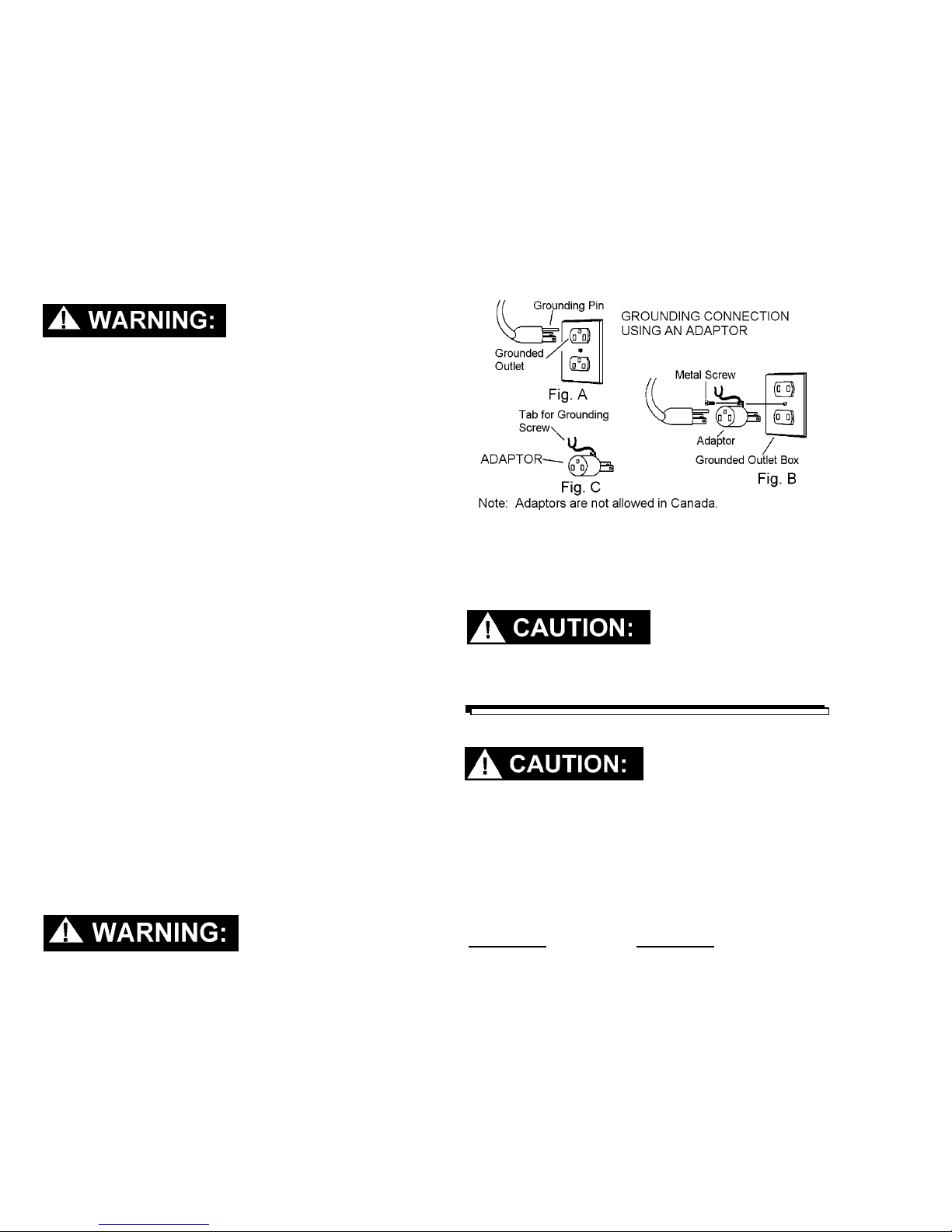
GROUNDING INSTRUCTIONS:
This appliance must be grounded. If it should
malfunction or break down, grounding provides a path of
least resistance for electric current to reduce the risk of
electric shock. This appliance is equipped with a cord
having an equipment-grounding conductor and
grounding plug. The plug must be inserted into an
appropriate outlet that is properly installed and grounded
in accordance with all local codes and ordinances.
“Fig . C” may be used to connect this plug to a 2-pole
receptacle as shown in “Fig. B”, if a properly grounded
outlet is not available. The temporary adaptor should be
used only until a properly grounded outlet (Fig. A) can
be installed by a qualified electrician. The green colored
rigid ear, lug, or wire extending from the adaptor must
be
connected to a permanent ground such as a properly
grounded outlet box cover. Whenever the adaptor is
used, it must be held in place by a metal screw.
EXTENSION CORDS:
If an extension cord is used, the wire size must be at
least one size larger than the power cord on the
machine: This extractor is equipped with a 25 ft. 16/3
power cord.
To avoid possible distortion of polyethylene
solution/recovery tanks, DO NOT USE WATER
TEMPERATURE THAT EXCEEDS 140 F (60 C).
CHEMICALS
Use only the suitable chemicals listed below.
Using incompatible chemicals will damage the
machine. Damages of this type are not covered
under warranty. Carefully read ingredients on
manufacturer’s label before using any product in
this machine.
Improper connection of the equipment-grounding
conductor can result in risk of electric shock.
Check with a qualified electrician or service
person if you are in doubt as to whether the outlet
is properly grounded. Do not modify the plug
provided with the appliance – I is will no fit the
outlet, have a proper outlet installed by a qualified
electrician.
This appliance is for use on a nominal 120-volt circuit,
and has a grounded plug that looks like the plug in “Fig.
A”. A temporary adaptor that looks like the adaptor in
6
Suitable Incompatible
Chemicals Chemicals
Alkalis Aldehydes; Butyls
Defoaming Agents Carbon Tetrachloride
Detergents Chlorinated Bleaches
Soaps Chlorina ted H ydroc ar bo ns
Vinegar Trichlorethylene
Hydroxides Phenols; Methyls (MEK)
Perchlorethylene (perc)
Aromatic Hydrocarbons
D-Limonene
EXP 98363 7/1/96
Page 7
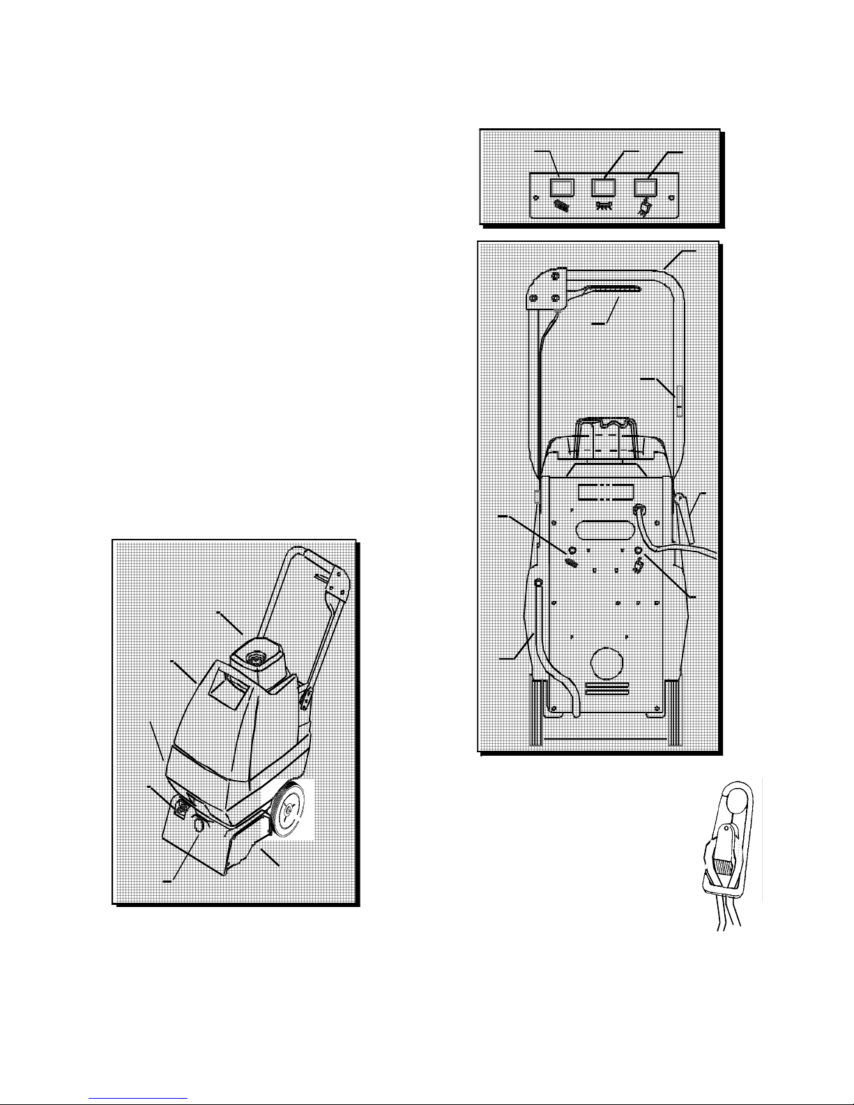
OPTION CONTROL
1 Brush Switch On/Off.
2 So lut io n Switc h On/O f f.
3 Vac Sw itch On/Off
4Main Handle.
5Solution Lever.
flow of solution to the floor .
6 Brush Motor Circuit Breaker.
Protects brush motor from overheating.
7 Vac Motor Circui t Breaker.
vac motor from overheating.
8 Ha n d l e Adj ustme nt L eve r.
Adjusts the ma in handl es angle.
9. Solution T ank Drain Hose.
10. Accessory T ool Connection.
ac ces s ory t o ol s.
1 1. Access ory Hose Connection.
conne ction for accessory tool.
12. Cord Hook.
Turns brush motor on and off.
T urns solution pump on a n d off.
. Tur ns va cuum mot or on a nd off .
Controls the amou nt of
Protects t h e
Solution connection f or
Hose
VIEW : TOP of CONTROL
1
VIEW: REAR of MACHIN E
5
6
23
4
12
8
VIEW: FR ON T of MA CHIN E
Dome
Recovery
Tank
Solution
Tank
10
11
Vacuum
Shoe / Brush
Housing
9
NOTE: Attach strain relief/cord
retainer to the pow er cord.
Make a loop in power cord appr oxim atel y
1.
12” from strain re li ef on machine .
Slide cord loop through slot
2.
in retainer arm. Pull slack
cord back through slot to
secure. Attach ret ainer t o
handle.
7
EXP 98363 03/24/00
7
Page 8

OPERATIONS
I
I
s
t
d
s
-
-
n
e
OPERATING INSTRUCTIONS
A. FI LL ING T HE S O LU TION TA NK:
Remove clear dome from recovery tank .
1.
Lif t upper recovery tank from machine and set
2.
aside.
Use a clean bucket or hose to fill so lution tank with
3.
hot wat er. The solution tank holds 4 gallons (15.2
liters) of cleaning solution.
Do not use the recovery tank to fi ll the solution tank. Sediment i n the recovery t ank can damage the solution pump
and clog the spray j ets, rendering the machine inoperable.
Add a non-foam ing c oncentrate for use in hot
4.
water extractors at the proportions noted on the
container.
Note: Periodically operate ext ractor with only hot water to remove chemical residue in carpet.
To avoid possible distortion o f polyethylene solution /recovery tan ks, DO NOT USE WATER WITH A TEMPERATURE TH AT EXCE EDS 140° F (60° C ).
Place recovery tank back on m achine.
5.
Place dome on rec overy tank. Make sure dome is
6.
seated c orrectly to ensure proper vacuum seal.
NOTE: If solut i on does not dispense in an even patt ern acros
the width of the machine, the spray jet may be clogged. Til
the machine back and remove the spray tip by pushing in an
tur ning i t one quarter t urn. Was h i t t horoughly, and blow dry.
NOTE: Do not use pins, wire, etc . to clean spray jet nozzle a
this will deform the jet and destroy the spray p att er n.
Begin with t he machine at the edge of the carpet.
6.
While operat ing machine, check for excessi ve fo am buil d
up in the recovery tank. If excessive foam is present, add
a d efoamer solution to reco very tan k, or empty tank.
7.
8.
Actuate the solut ion lev er while pulling the machine
backwards. Release solution lever at least 12
inc hes before the end of each cleaning p ass . This
will ensure all dispensed cleaning solution is
extrac ted from carpet.
Empty recovery tank when approximately 3/4 full.
If the recovery tank is overfilled , the water will drain
back ont o the carpet when the vacuum is sw itched
off.
Ven tilate area after carpet has bee n cleaned.
Ke ep childr en and pets aw ay and do not w alk
on carpet until it is dry.
Use only the suitable chemicals listed above. Using incomp atible ch emicals will damage the machine. Caref ully
read ingredients on man ufacturer’s label b efore usin g any
pr od uc t in this m a c hi ne .
I
OPERATING THE MACHINE
Vacuum the carpet and make sure it is cleared of
1.
surface debris before cleaning.
Plug power cord into a grounded wall outlet.
2.
Defeatin g the grounding pin on the power cord can result
in a severe electrical shoc
Turn on the pump, brush and v acuum
3.
swit ches, listeni ng for each motor to turn on.
NOTE: The vacuum and the brush are protected by circuit
breakers located on the back panel, below their respective
switch.
NOTE: If either of these motors does not respond to being
swit ched on, res et the circ uit breakers by pressing them in, and
attempt to switch the machine on again.
k.
A Windbloweräfan can be used to reduce drying time.
III
OPERATING MACHINE WITH
ACCESSORY TOOLS
This extractor is easil y adapted for use the following
Windsor accessory tools: DHT-UPH3-SW-SFW-SW/PRO
DDH-SPW
1.
2.
3.
Do not switch on brush when operating the machine
w ith acce ssory too l s. C arp et damage may occur.
NOTE: The s olution pump is not intended to run dry. W he
using the extractor for vacuum pick-up only, insure that th
pump swit ch is turned off.
Lift flap on the front of vac shoe and insert hose cuff
into the vac shoe, ensuring that there is a tight fit.
Attac h the solution hose from accessor y tool to the
brass soluti on fitti ng on the front of machi ne.
Switch on the pum p and the vacuum. The applic ation of cleaning solution is now controlled by
the lever on the accessor y tool.
OPERATING THE MACHINE
cont..
8
EXP 98363 03/24/00
Page 9

PROTECT FROM FREEZING
E
If it becomes necessary to store in tem peratures t hat could
drop below 40° F, the pumping sy stem, hos es and valves must
be protected from freezing with a methyl hy drate window wash-
er antifreeze solution
NOTE:Do not use ethylene glycol or cooling system
antifreezes.
Add on a gallon of window washer antifreeze
1.
.
to the sup ply tank.
Tu rn on pump switch and spray unti l the
2.
antifreeze so lu tion fi lls the solution lines.
Drain ou t the leftover antifreeze from the
3.
supply tank. Always allow the unit to reach
room temperatures before filling with h ot
water or op erati ng.
DA ILY /R E GU L A R M AI NT E NA N CE
! WARNING
Before making any adjustments or repairs to th e
machi n e, d i scon ne ct the power co r d for m e lect r i cal
source.
Empty unused cleaning solution f rom the
1.
s o lutio n ta nk.
Inspect and clean fil ter screens in solution tank, and
2.
on top of tube in recovery tank.
Flush pumping system wit h 1 or 2 gallons of
3.
cl ean, hot water.
MAINTENANCE
Periodic ally inspect all hoses, electrical cables, fil ters,
3.
gaskets and connections on your machine.Frayed or
cracked hoses should be repaired or replac ed to
elimi nate vacuum or solution pressure loss.
The electric al cable must be well insulat ed, if the cable
4.
ins ulation is broken or f rayed, re pair or replace it
im mediately. D on’t t ake chances with elec trical f ire or
shock.
The filt er in the bottom of the solution tank must be
5.
clean to allow free flow of cleaning solution. The screen
f ilter on the vacuum tube in the recov ery tank mus t be
f ree of lint buildup to ensure fu ll vacuum strength.
The dome gask et must be properly s eated and free of
6.
damage to creat e the air seal needed t o extract water.
MAINTENANCE INSTRUCTIONS
! WARNING
Remove machine power cord from electrical source
befor e makin g an y ad justm en ts o r r ep air s to the m a-
chine.
! WARNING
Only qualified maintenance p ersonnel a re to perform repairs.
BRUSH ASSEMBLY
Situate machine in order to access bottom cover. Remove
1.
screws (6) and bottom cover. Remove screws (3) and
belt cover.
C h e ck spra y j e t fo r fu l l spray p a tter n .
4.
Empty th e recovery tank and rins e with clean
5.
w a te r.
Check fo r and rem ove any lint or debris around
6.
brush and v ac shoe .
PE RIODIC MAINTENANCE
After every 25 hours of operation, flush a white
1.
vi negar solution (ONE quart vinegar to two
gallons of water) or anti-browning solution
(mixed as directed) through t he extractor. T his
will prevent build-up of alka line residue in t he
system.
If the spray jet becomes clogged, remove the
2.
spray tip, wash it thoroughly, and blow dry.
NOTE: Do not use pins, wire, etc. t o clean spray jet nozzle as
thi s will deform the jet and destroy the spray p atter n.
PERIODIC MAINTENANC
cont..
EXP 98363 03/24/00
Loosen nuts at brush motor and slid e motor forward
2.
to reduce belt tension. R emove belt.
Remove lower brush st op on belt side (closest to you with
3.
machine upside down) and rotate b lack plastic finger
guard tow ard rear of machine.
Remove one s crew holding each brush bearing t o
4.
brus h bracket .
With the blade of a screw drive, bend bearings
5.
inward enough to disengage locating tabs .
Slide brush, axle, and bearing out of brush bracket.
6.
Ins pect/replace brush and bearings as required.
7.
The brush is equipped with yellow wear indicator
bris tles. The brush should be replac ed when it
wears down to the height of the yellow bristles .
When reinstalling brus h, chec k belt for proper
8.
tens ion.
9
Page 10

MAINTENANCE
TO ACCESS PUMP AND BRUSH MOTOR
1. Situate machine in order to access bottom
cover. Remove screws (6) and bottom cover.
2. To remove brush motor, loosen nuts at brush
motor and slide motor forward to reduce belt
tension. Remove belt. Continue loosening nuts at
brush motor until free from brush bracket.
Disconnect wires.
3. To remove pump, loosen screws holding pump
mounting bracket to casting and remove as one unit.
Lift pump and mounting bracket up to gain access to
all hose clamps which need to be removed before
pump is free from machine. Disconnect wires.
TO ACCESS VAC MOTOR
Lift off recovery tank.
1.
2. Remove screws (5) and lift off vac motor
cover.
3. Vac motor can be lifted out and electrically
disconnected.
NOTE: The vac motor is protected by a circuit breaker
located in the switch panel. The breaker will only trip
under conditions of abuse.
SOLUTION VALVE CABLE ADJUSTMENT
The solution valve cable has been factory set so that
action of the solution lever moves the valve from fully
closed to fully open. As the machine operates the cable
will stretch and the lever will not be able to fully open the
valve. The play in the solution lever should be checked
periodically and adjusted when needed as described
below.
1. Loosen the lock nut at the point where the cable
enters the lever housing on the machine handle.
2. Turn the threaded end of the cable sleeve to
adjust. Threading the end further into the
housing will slacken the cable, increasing the
play in the lever. Threading the end out of the
housing will tighten the cable, decreasing the
play in the lever.
4. When replacing the vac motor, make sure
the excess wire lengths do not get pinched
in the gaskets which seal the vac motor. If
need be, remove the rear control panel and
pull excess lead length out of the vac motor
compartment.
VAC MOTOR BRUSHES
1. To inspect motor brushes, remove vac
motor from tank by disconnecting wires.
Then remove black vac motor fan housing
and brush holder assembly.
be replaced when worn to 3/8 inch or after about
750 operating hours. After second brush
replacement, the armature commutator should
be checked for pitting and concentricity. Vac
motors can be repaired, but such repairs should
be made by a qualified motor repair shop.
VAC MOTOR
location
of brushes
en d cap
ground
Brushes should
3. Tighten the locking nut against the housing after
adjusting the play as required.
4. If there is not enough thread adjustment
available, the cable length can be adjusted
directly at its connection to the solution valve.
This is accessed by removing the back control
panel.
SPRAY JET
Note: To prevent a clogged jet due to alkali build-up,
the spray system should be flushed with 1 to 2 gallons
of clean hot water at the end of each day.
1. Situate machine in order to access bottom cover.
2. The machine is equipped with a ”Quick Change”
jet that can be easily removed for cleaning. To
remove- push jet in and rotate 1/4 turn.
3. Wash jet and blow dry. Do not use pins or wire
to remove obstruction as this will change spray
pattern.
3/8
VAC MOTOR BRUSHES cont..
NOTE: When replacing electrical component parts refer
to Wiring Diagram for proper connection.
10
EXP 98363 03/24/00
Page 11

TROUBLESHOOTING CHART
A
No Pow er To Machine:
Dead electrical circuit breaker in fuse box
Fau lt y po wer cord
Power sw itc h f ailure
Faulty circuit breaker
Internal wiring problem
El ect rical Sho c k:
Equipment not grounding
Receptacle not grounded
I nternal ele ct rical p robl em
N uisance Tripping of Circuit Breaker:
Faulty circuit breaker
Mechanical problem
Va c u u m M o t o r S p e ed
Varies or Doesn’ t Run:
Worn motor brus he s
Motor worn out
Fau lt y sw itc h
Faulty circuit breaker
Internal wiring problem
Loss Of V acuum:
Loose vac dom e
Incorre ct se ating of recove ry tank.
Crack in dome or poor joint
Damaged dome gasket
Lint or dirt clogging vacuum intake screen
ccessory tool clogged
I nternal ele ct rical p robl em
Accessory Tool Fitting Diff icult to Connect:
Cor rosion on fitting
Brush Not Turning:
Belt broken
Fau lt y sw itc h
Faulty circuit breaker
Faulty brush motor
Worn Bearings:
Squealing or grinding sound in brush housing
Carpet Not Getting Clean:
Severe soil condit ion s
Car pe t Too Wet:
Worn spray jet (s)
Carpet Not Getting Wet:
Solution filter s creen clogged
Spray jet(s) clogged
Pump not running
Fau lt y pu mp
Solution valve adjustm ent
Incorrect jet orientation
Corre ctive Action:
Che ck buil din g circ ui t breaker.
Replace power switch f ailureTest switch for continuity/Replace if necessary.
Test circuit breaker for continuity. Replace if necessary. With the m achine
unplugged, check for, and correct, any loose wire
connections inside the machine at the switches and t erminal block.
Fol l ow ground i ng instructions exact l y.
Have an electrician inspect the building’s wiring.
Ensure that the mac hi ne’s wiring matches the appropriate wiring diagram.
Check for and co rrect any loos e w ire c on nections. Replace any wires o r
component s whic h are short circuiting.
Turn brush motor and pump switches on wi th machine til ted rearward (brush
off f loor). Lower mach ine back to carpet slowly.
Test circuit breaker for continuity/Replace if necessary.
Higher amp draws may indicate a mechanical problem. Find parts which are
not moving freely and repair or replace.
Replace
Replace
Replace
Replace
Check f or and correct any loose wire connec tions,
Seat dome squarely over tank opening.
. Remove recovery tank , clean of f seals on top of solution t ank, and reseal
recove ry tank .
Repl ace or repair using acrylic plastic c ement only.
Repl ace gasket.
With pow er off clean v ac intake screen found in dom e.
Clean out tool, ensure free air flow.
Have a trained service tec hnician inspect and repair the machine.
Clean with steel wool.
Remove and soak in acetic acid (white vinegar).
Lubr icate light ly with s ilicone ba se lubrican t .
Remove belt cover on right side of machine.
Inspect belt Replace if necessary.
Replace.
Replace.
If t he belt, circuit breaker, and switch have been tested and found to be in
good w orking order, the brush motor may need to be replaced.
Repl ace beari ngs.
Make s everal passes at right angles to each other.
Use a pre-spray.
Replace spray jets which are producing more than a fine mist.
C lean s olution filter sc reen loc ated inside lower tan k near the front.
Clean or replace jets.
Damaged jets will cause over-saturation.
Check for and correct any loose wires
R epa ir or replac e
Adjust solution valve cable unt il valve operates wh en handle is pulled.
Align slit in jet par allel wit h cen ter line of brush .
Do not use a wire to clean jet.
EXP 98363 03/24/00
11
Page 12

WIRING DIAGRAM
115V EXPERT
ORG
BLK
15
12
EXP 98363 03/24/00
Page 13

3
SERVICE SCHEDULE
MAINTENANCE DAILY WEEKLY QUARTERLY
Check machine for cord damage
Check recovery dome and gasket for
damage and cleanliness
Check brush – should be clean with no
lint or strings attached
Inspect vac shoe for blockage; remove
fibers with coat hanger, etc.
Check hoses for wear, blockages, or
damage
Check handles, switches, and knobs
for damage
Check vac motor intake filter and clean
Run one gallon of water through
system
Clean out recovery tank and check
float valve to make sure it moves freely
Clean out solution tank and remove
and clean vacuum intake screen
Clean outside of all tanks and check for
damage
Run vac motor for at least one minute
to allow motor to dry
Store with dome off tank to allow the
tank to dry
Check all bearings for noise
Check all gaskets for wear and leakage
Check vacuum intake screen for
damage; replace if necessary
Check pump pressure; observe spray
pattern and check with gauge if
necessary
Check and clean solution screen
Check belts for wear and replace as
necessary
Check brush for wear; ensure bristles
are not damaged
Check cables for fraying
Check the spray bar (manifold) for
damage; replace if broken or bent
Check condition of vac shoe and frame
for damage
Check overall performance of machine
Check vac motor carbon brushes
MAINTENANCE
*
*
*
*
*
*
*
*
*
*
*
*
*
*
*
*
*
*
*
*
*
*
*
*
*
EXP 98363 10/19/02
1
Page 14

VAC/SOLUTION TANK/CONTROL PANEL
1
44(5)
2
4
5
8A
10
45(5)
24
41
43
12(2)
45(2)
16
25(3)
33
17
32(2)
31
23
19
9
20
14
6
7
30
12
48(2)
27
44(6)
13(2)
37
38
11
26(4)
35(4)
46
3(4)
40(2)
49
31
39(4)
42
36
18
31(2)
34
47(2)
29
28
15
44 REF
45(6)
21(2)
22(2)
14
EXP 98363 10/22/01
Page 15

VAC/SOLUTION TANK/CONTROL PANEL PARTS LIST
REF PART NO. QTY DESCRIPTION
1 35175 2 GASKET, TANK TO VAC COVER
2 27631 1 COVER, VAC MOTOR
3 70627 4 SCR, 1/4 X 1/2 PPHST HI-LO 443236
4 27759 1 CUFF, 1.5” BLACK HOSE
5 39276 1 HOSE, 1.5” X 14” VAC
6 57208 1 NUT PG11 METAL, 1.024 OD X 0.73 ID
7 70211 1 SCR, 10-32 X 3/4 PH. BLK NYLON
8A 53771 1 VAC MOTOR ASM, 115V EXP.
8B 53780 1 VAC MOTOR ASM, 100V EXP.
9 500551 1 LABEL, CONTROL PANEL MAIN
10 27632 1 CAP, VAC MOTOR
11 34331 1 FRAME/SOL EXP II
12 70532 3 SCREW, 10-32 X 1/2 PHMS BLK
13 14942 2 COVER, CIRCUIT BREAKER
14 72151 3 SWITCH, 125V SPST
15 14622 1 BREAKER, 1.5A CIRCUIT
16 27787 1 COVER, REAR (CONTROL PANEL)
17 14700 1 BREAKER, 15A 250 VAC 50 VDC 1000001018
18 03102 1 AXLE, WHEEL
19 23664 1 CORD ASM, 115V
20 73710 1 STRAIN RELIEF, PG11 METRIC TRUMPET
21 89048 2 WHEEL, 8” NON-MARKING
22 57196 2 HUBCAP, 1/2” DIA
23 14020 1 TERMINAL BLOCK
24 35169 1 GASKET, VAC COVER
25 27376 3 CLIP, SWITCH RETAINING
26 70393 4 SET SCR, 1/4-20 X 1.25L
27 70595 1 SCREW, 10-32 X 1 PHMS GRN
28 880041 1 WIRE ASM, PANEL TO BASE
29 20086 1 CLAMP, CORD
30 70547 1 SCREW, #10-32 X 1 PPHMS BLK
31 57104 4 NUT, #10-32 KEPS
32 57116 2 NUT, #6-32 KEPS
33 87100 1 WASHER, 3/8 INT. LOCK THIN
34 35222 1 GASKET, 2 ID X 2.75 X 3/8 THK PORON
35 35182 4 GASKET, FRAME
36 73864 1 STRAINER, 3/8” NPT 60 MESH
37 500226 1 LABEL, CIRCUIT BREAKER BRUSH
38 500225 1 LABEL, CIRCUIT BREAKER VAC
39 70517 4 SCREW, 8-32 X 1/2 FHMS SS
40 51254 2 LOCK, HANDLE EXPERT TANK
41 35193 1 GASKET, REAR COVER
42 67029 1 RECTIFIER, BRIDGE
43 50776 1 LABEL, FOR SAFETY
44 70626 11 SCR, 10-3/4 PPHST TYPE B BLK
45 87189 13 WASHER, .2 ID X .5 OD BLK SS
46 62717 2 PLATE, AXLE EXP
47 87146 2 WASHER, 1/2 ID X 1” OD X .08” NYLON
48 70235 2 SCREW, 6-32 X 1.0 PH BLK NYLON
49 20035 1 CLAMP, 7/16 DIA. NYLON UL 1000028686
SERIAL NO.
FROM
NOTES:
EXP 98363 10/22/01
15
Page 16

BRUSH/BRUSH MOTOR/FRAME
Vac H ose
REF.( 39276)
REF
12
29
28
Part of
item 28
42
2
27
39468
33
Brush brkt
5
4
1
outside
of
machine
Housing
13
32
Diagram A
30
18
20
See
Dia gram B
14
34
13(2)
42
19
See
Diagram C
37
23
17
21
See
Diagram A
16
13(2)
6
10(3)
15
24
8(2)
22
11
36
30
Brush brkt
Housing
13
32
Diagram B
7(2)
35(2)
39
Wiring Asm.
REF. (88004)
40
Inside rear wall of housing
37
8(4)
Housing
outside
of
machine
33
10(5)
26
16
44
43
EXP 98363 10/17/01
41(4)
9(4)
*-left side only
Diagram C
Page 17

BRUSH/BRUSH MOTOR/FRAME PARTS LIST
REF PART NO. QTY DESCRIPTION
1 41279 1 HOUSING, BRUSH W/VAC SHOE
2 27674 1 COVER, ACCESS PORT
3 - - OPEN
4 35195 1 GASKET, .25 X .75 X 2.00 L
5 27759 1 CUFF, 1.5” BLACK HOSE
6 67138 1 RING, 3/8 EXTERNAL SNAP
7 57104 2 NUT, 10-32 W/STAR WASHER SHOE
8 57030 6 NUT, 10-32 NYLOCK
9 70557 4 SCR, 10-32 X 1” FHMS BLK
10 70532 5 SCR, 10-32 X 1/2 PPHMS BLACK
11 27636 1 COVER, BELT
12 20016 1 CLAMP, 1/4 ID HOSE
13 87139 4 WASHER, 3/16 FLAT
14 09113 1 BEARING, RIGH T
15 70740 3 SCR, 10-32 X 1/2 PTHMS BLK
16 64085 1 PULLEY, MOTOR
17 53608 1 MOTOR ASM, BRUSH DRIVE
18 140036 1 BRACKET ASM, BRUSH MOTOR
19 09114 1 BEARING, LEF T
20 140040 1 BRUSH
21 64086 1 PULLEY, BRUS H
22 11039 1 BELT, BRUSH DRIVE
23 03084 1 AXLE, BRU SH
24 35176 1 GASKET, BOTTOM COVER
25 - - OPEN
26 27639 1 COVER, BOTTOM
27 35171 1 GASKET, ACCESS PORT COVER
28 140087 1 BULKHEAD, 1/4 MPT X 1/4 BARB
29 56012 1 NIPPLE, 1/4 FPT QD
30 70303 2 SHOULDER BOLT, 1/4 OD X 5/8 L
31 - - OPEN
32 09117 2 BEARING, BRUSH BRACKET
33 57018 2 NUT, 10-24 HEX LOCK
34 70578 2 SCREW, 8-32 X 1” FHMS SS
35 70031 2 SCR, 10-32 X 1/4 PPHMS
36 87003 1 WASHER, 3/8 ID X 7/8 OD SS
37 62556 1 PLATE, GUARD ON LEFT SIDE ONLY
38 - - OPEN
39 70595 1 SCR, 10-32 X 1.0 PHMS GRN
40 20086 1 CLAMP, CORD
41 73781 4 HOSE, 5/16 X 3/16 ID CLR VINYL
42 70351 4 SCR, 10-32 X 3/8 HHTR W/STAR
43 70604 1 SCR, 10-32 X 5/8 PHMS BL K
44 87189 1 WASHER, .2 ID X .5 OD BLK SS
SERIAL NO.
FROM
NOTES:
NOTE: The left and right sides of the machine are
assigned as if standing behind the machine in the
operator’s position.
EXP 98363 10/17/01
17
Page 18

PUMP ASSEMBLY
10
13
9
12
Valve
5(2)
6(2)
8
11(2)
4
1(2)
7
So lut ion Ta nk
2
14
18
1
3
Accessory Port
EXP 98363 03/27/00
NOTE: Head of screw on this
hose clamp shall point towards
center of pump head as shown.
Page 19

PUMP ASSEMBLY PARTS LIST
REF PART NO. QTY DESCRIPTION
1 20016 2 CLAMP, 1/4 ID HOSE
2 39510 1 HOSE, 3/8 WIREBOUND X 3”
3 39468 1 HOSE, 1/4 NYLOBRAID X 11.5”
4 39508 1 HOSE, 1/4 NYLOBRAID X 15”
5 70484 2 SCR, 10-32 X 5/8 PPHMS SS
6 87016 2 WASHER, #10 LOCK EXT. ST AR
7 140034 1 BRACKET, PUMP
8 40009 1 HOSEBARB, 1/4 MPT X 1/4
9 40065 1
10 65164 1 PUMP ASM, EX PERT
11 70581 2 SCR, 10-32 X 3/8 HHTFW/WASH
12 78024 1 TEE, 1/4 BRANCH
13 40033 1
14 20042 1 CLAMP, 3/8 (D-SLO T )
HOSEBARB, 1/4 MPT X 1/4 X 90°
HOSEBARB, 1/4 MPT X 3/8 90°
SERIAL NO.
FROM
NOTES:
EXP 98363 03/27/00
19
Page 20

SOLUTION LEVER/MAIN HANDLE
S ol ution Lever
5
4(3)
3
16
1(3)
34331
REF
3
41 REF
2
12
9
8
42(2)
38
7
6
VIEW A-A
31
T
E
R
X
P
32
E
17
11
15
14
13(2)
28
33
12(2)
18
20
29(2)
A
A
B
30A
30B
34(4)
19
10
21
See Rear View
B
35
27
22
41
39(2)
36
42
A
40
26
23(2)
Rear View
A
43
37
20
EXP 98363 03/27/00
Page 21

SOLUTION LEVER/MAIN HANDLE PARTS LIST
REF PART NO. QTY DESCRIPTION
1 57238 3 NUT, 10-24 JOINT CONNECTOR BLK
2 51251 1 LEVER, SOLUTION
3 41302 2 HOUSING, SOLUTION LEVER
4 70537 3 SCR, 10-24 TRUSS HEAD BLK
5 36046 1 GRIP, HANDLE X 13”
6 38247 1 HANDLE
7 27785 1 CABLE, VALVE SOLUTION 27-1/2 LG
8 87029 1 WASHER, 5/16 FLAT SAE 441847 WAS 57138 (QTY 1)
9 57234 1 NUT, 3/8-16 SQUARE
10 57022 1 NUT, 3/8-16 HEX NYLOCK
11 87080 1 WASHER, .52 1.25 FLAT PLTD
12 87016 3 WASHER, #10 LOCK
13 87139 2 WASHER, 3/16 FLAT USS 441847 (QTY WAS 3)
14 67397 1 ROD, HANDLE ADJUSTMENT EXP II
15 80604 1 RING, RUE COTTER 1/4”
16 51142 1 LEVER, HANDLE LOCK
17 66133 1 PIN, CLEVIS
18 51184 2 LOCK, HANDLE ADJUSTMENT
19 62716 1 PLATE, STOP EXPT
20 73735 1 SPACER, 1.0 OD X .26 ID X 1 BLK NYL
21 70556 1 SCREW, 1/4-20 X 1.5 SS
22 84153 1 VALVE, KING STEN
23 40065 2
24 - - OPEN
25 - - OPEN
26 57018 1 NUT, 10-24 LOCK
27 89144 1 WELDMENT, LEVER VALVE EXP
28 41144 1 HOOK, CORD
29 70361 2 SCR, #10-32 X 1/2 PHTR
30A 50729 1 CARD, INSTRUCTION
30B 50765 1 CARD INSTRUCTION EXP J
31 27417 1 CORD, 1/8 X 12”
32 73169 1 STRAIN RELIEF, CORD HOOK
33 99620 7” HEAT SHRINK, 3/8 ID UL/CSA
34 70031 4 SCR, 10-32 X 1/4 PPHMS PLTD
35 40043 1
36 39508 1 HOSE, 1/4 NYLO BR AID 15”
37 39507 1 HOSE, 1/4 NYLO BR AID 17”
38 88551 1 WIRE ASM, 19” GRN/18 78008 X 78008
39 20016 2 CLAMP, 1/4 ID HOSE
40 73866 1 SPACER, 1/2 OD X .219 ID X 1/2 NYLON
41 140308 1 BRACKET, VALVE EXPERT
42 70626 3 SCR, 10-3/4 PPHST TYPE B BLK
43 66086 1 PIN, ROLL 3/16 X 5/8
HOSEBARB, 1/4 MPT X 1/4 90°
HOSEBARB, 3/8 MPT X 3/8 90° NYLON BLK
SERIAL
NO.
NOTES:
EXP 98363 03/27/00
21
Page 22

RECOVERY TANK
8
5
4(3)
9
TO REAR
COVER
1
7
10
3
2
6
11
22
EXP 98363 03/27/00
Page 23

RECOVERY TANK PARTS LIST
REF PART NO. QTY DESCRIPTION
1 28050 1 DOME
2 35178 1 GASKET, DOME
3 62465 1 PLATE, COVER
4 70114 3 SCR, 10-32 X 3/4 POLYFAST
5 35167 1 GASKET, COVER
6 75212 1 TANK, RECOVERY
7 34140 1 FILTER, VAC INTAKE
8 78162 1 TUBE, 1.5 PVC X 4.88”
9 27417 1 CORD, 1/8 X 1/2”
10 500009 1 LABEL, WARNING
11 500016 1 LABEL, EXPERT
SERIAL NO.
FROM
NOTES:
EXP 98363 10/22/01
23
Page 24

SOLUTION PLUMBING/SPRAY JET
5
1
2
39507
REF
7
12
10
9
4
TO
PUMP
3
2
24
EXP 98363 03/27/00
Page 25

SOLUTION PLUMBING/SPRAY JET PARTS LIST
REF PART NO. QTY DESCRIPTION
1 40069 1 HOSEBARB, 3/8 NPT X 3/8 TEE
2 20016 2 CLAMP, 1/4 ID HOSE
3 20042 1 CLAMP, 3/8 HOSE
4 31028 1
5 39509 1 HOSE, 3/8” CLEAR X 15.5”
6 62800 1 PLATE, GUARD EXPERT
7 40064 1 HOSE BARB, 1/8” FPT X 1/4”
8 - - OPEN
9 44066 1 JET, BRASS MINI-QUICK
10 44052 1 JET BODY, MINI-QUICK W/SEAL
11 - - OPEN
12 87185 1 WASHER, 3/8 SEALING X 3/4 OD
ELBOW, 1/8 45° STREET
SERIAL NO.
FROM
NOTES:
EXP 98363 03/27/00
25
Page 26

SPARE PARTS AND ACCESSORIES
PART NO. DESCRIPTION
11039 BELT, BRUSH DRIVE
35178 GASKET, DOME
35171 GASKET, ACCESSORY PORT
140040 BRUSH, EXP
44066 JET, 11004 BRASS MINI-QUICK
44051 JET SEAL, MINI-QUICK
44052 JET BODY, MINI-QUICK W/SEAL
35175 GASKET, TANK TO VAC COVER
50729 INSTRUCTION CARD
09114 BEARING, LEFT
09113 BEARING, RIGHT
64085 BRUSH MOTOR PULLEY
64086 BRUSH PULLEY
35176 GASKET, BOTTOM COVER
73169 STRAIN RELIEF, CORD HOOK
34140 FILTER, VAC INTAKE
ACCESSORIES
SW – STANDARD WAND
SPW – STANDARD WAND PROFESSIONAL
DHT – DELUXE HAND TOOL
DHTK – DELUXE HAND TOOL KIT
DDH – DOUBLE DRY HAND
26
EXP 98363 03/27/00
Page 27

WINDSOR INDUSTRIES
New Machine Warranty
Limited Warranty
Windsor Industries, Inc. warrants new machines against defects in material and workmanship under normal use and service to the
original purchaser. Any statutory implied warranties, including any warranty of merchantability or fitness for a particular purpose, are
expressly limited to the duration of this written warranty. Windsor will not be liable for any other damages, including but not limited
to indirect or special consequential damages arising out of or in connection with the furnishing, performance, use or inability to use
the machine. This remedy shall be the exclusive remedy of the buyer. The warranty period is subject to the conditions stated below.
6 / 3 / 1 Warranty: 6 Years Polyethylene (PE) Housings, 3 Years Parts, and 1 Year Service Labor
Subject to conditions outlined below, Windsor Industries warrants rotationally molded PE housings and parts on all of its machines to
be free from defects in material and workmanship, under normal use and service for six (6) years to the original owner.
Under this warranty we guarantee the performance of non-polyethylene parts and components to be free from defects and for up to
three (3) years to the original end user. Parts replaced or repaired under this warranty are guaranteed for the remainder of the original
warranty period. (See table below)
Service labor charges are covered for up to one (1) year from the date of purchase through authorized Windsor service provider. No
travel coverage is extended for cord-electric models. See table below for each general product model warranty coverage.
Product PE Housing & Parts Non- PE Parts Service Labor Travel
Rider Scrubbers 6 years 3 years 1 years 6 Months
Rider Sweepers 6 years 1 year 1 years 6 Months
Walk Behind Scrubbers 6 years 3 years 1 years 6 Months
Walk Behind Sweepers 6 years 1 year 1 years 6 Months
Extractors 6 years 3 years 1 years Polishers / Elec. Burnishers / GH 6 years 3 years 1 years Wide Areas Vacuums 6 years 3 years 1 years VacPak Vacuums 6 years 1 year 1 year Air Movers / Dri-matic / TITANä
Propane Burnishers / Strippers - 2 year 1 year Tracer/Flex Sweepers/Scrubbers 6 years 2 year 6 months 90 days
1 year 1 year 1 year -
VERSAMATICÒ
SENSORÒ
Product exceptions and Exclusions:
· Extractor brush motors, pump motors, ALL PC boards and electronics, ALL Vacuum motors (other than VERSAMATICÒ and
SENSORÒ), ALL pumps, and FLEXSOLä diaphragms carry a one (1) year parts and service labor warranty.
· The OnanÒ engines have three (3) year manufacturer’s warranty. The HondaÒ and KawasakiÒ engines have two (2) year
manufacturer’s warranty. NOTE: The engine warranty is administered through the engine manufacturer and must be repaired at
an authorized service center.
Normal wear items and accessories including, but not limited to, belts, brushes, capacitors, carbon brushes, casters, clutches, cords,
filters, finishes, gaskets, hoses, light bulbs, rectifiers, switches, squeegees, bearings, pulleys, relays, actuating cables, wheels, tires,
propane tanks, and batteries will be warranted for manufacturing defects for 90-days from the purchase date.
The warranty commences on the purchase date by the original end user from an authorized Windsor agent, subject to proof of
purchase. The Machine Registration Card must be completed and returned immediately at the time of purchase. If proof of purchase
cannot be identified, the warranty start date is 90 days after the date of sale to an authorized Windsor distributor. Parts replaced or
repaired under warranty are guaranteed for the remainder of the original warranty period.
Windsor Industries reserves the right to change its warranty policy without notice – Rev2 10/16/02 1
Windsor Industries, Inc. ● a Castle Rock Industries company ● 1351 W. Stanford Ave. ● (303) 762-1800 ● 800-444-7654 ● FAX (303) 865-2800
Brush motor, Vacuum motor, Belts – 3 years All other parts – 1 year
Vacuum motor, Belts – 2 years All other parts – 1 year
Page 28

WINDSOR INDUSTRIES
New Machine Warranty
90 Day Warranty Extension Available
Upon receipt of the Machine Registration Card, Windsor will extend by 90 days, from the date of purchase, all items included under
the one-year provision. This applies only to one-year items and does not include 90-day wear items.
This Warranty Shall Not Apply To:
1. Any product that has been subject to abuse, misuse, neglect or unauthorized alteration (including the use of incompatible or
corrosive chemicals or overloading of capacity).
2. Products that have experienced shipping or freight damage.
3. Repairs necessary to correct any failure due to improper pre-delivery service and inspection by the selling dealer.
4. Excessive time for cleaning units in preparation for repair.
5. Any repairs resulting from poor initial service work or improper diagnosis.
6. Tune-up parts such as plugs, plug wires and condensers.
7. Any design alterations performed by an organization not authorized or specified by Windsor.
8. Battery and charger warranties are handled directly with the manufacturer (TrojanÒ batteries and LesterÒ chargers).
9. High-pressure washing.
10. Electrical components exposed to moisture.
If difficulty develops during the warranty period, contact the authorized Windsor agent from whom the product was purchased.
Windsor Industries, Inc. may elect to require the return of components to validate a claim. Any defective part to be returned must be
shipped freight prepaid to an authorized Windsor Distributor/Service Center or to the Windsor factory.
Use Of Parts Not Approved By Windsor Industries, Inc. Will Void All Warranties
This warranty is valid only for all products sold after July 1, 1995. A product sold before that date shall be covered by the limited
warranty in effect at the date of sale to the original purchaser.
Windsor Industries reserves the right to change its warranty policy without notice – Rev2 10/16/02 2
Windsor Industries, Inc. ● a Castle Rock Industries company ● 1351 W. Stanford Ave. ● (303) 762-1800 ● 800-444-7654 ● FAX (303) 865-2800
 Loading...