

Page 1

To Order Parts Call 1-888-702-5326 - https://monsterfloorequipmentparts.com
98255 9/15/97
INDUSTRIES, INC., 1351 W. Stanford A ve., Englewood CO 80110 USA *303–762–1800*F AX 303–762–0817
CONTENTS:
2 Safety Instructions
3 Grounding Instructions
4 Operating the Extractor
5 Operations and Maintenance
6 Service
7 Chassis assembly
8 Brush Housing and Drive Assembly
10 Tank Assembly
12 Wiring Diagrams
13 Notes
14 Warranty
Page 2

To Order Parts Call 1-888-702-5326 - https://monsterfloorequipmentparts.com
IMPORTANT SAFETY INSTRUCTIONS
When using an electrical appliance, basic precaution must
always be followed, including the following:
READ ALL INSTRUCTIONS BEFORE USING THIS MACHINE.
This machine is for commercial use.
WARNING: To reduce the risk of fire, electric shock, or injury:
1. Do not operate without filters (dry or wet) in place.
2. Use only as described in this manual. Use only manufacturer’s recommended attachments.
3. Use indoors only. Do not use outdoors and do not expose to rain.
4. Machine can cause a fire
machine near flammable fluids, dust or vapors.
5. Do not pick up flammable fluids, dust or vapors.
6. Do not vacuum anything that is burning or smoking, such as cigarettes, matches, or hot ashes.
7. Do not handle the plug or machine with wet hands.
8. Do not leave the machine unattended. Unplug machine from outlet when in use and before servicing.
9. Do not leave the machine unattended. Unplug machine from outlet when not in use and before
10. Do not unplug machine by pulling on cord. To unplug, grasp the plug, not
11. Do not use with damaged cord or plug. Follow all instructions in this manual concerning grounding the
machine.
12. If the machine is not working properly, has been dropped, damaged, left outdoors, or cropped into
water, return it to an Authorized service center.
13. Do not pull or carry by cord, use cord as a handle, close a door on cord, or pull cord around
sharp edges or corners.
14. Do not pull/run machine over cord. Keep cord away from heated surfaces.
15. Do not allow to be used as a toy. Close attention is necessary when used by or near children.
when operating near flammable vapors or materials. Do not operate this
servicing.
the cord.
16. Do not operate machine with any openings blocked. Keep openings free of debris that may reduce
airflow.
17. Keep hair, loose clothing, fingers, and all parts of the body away from openings and moving
parts.
18. Use extra caution when cleaning on stairs.
19. Do not use machine as a step.
20. Connect to a properly grounded outlet. See Grounding Instructions.
21. Maintenance and repairs must be done by qualified personnel.
22. Rotating fan blades inside the cover. Before opening cover, switch off machine. Wait until the fan/brush
stops completely or dust and debris may be ejected.
SAVE THESE INSTRUCTIONS
2
98255 7/1/97
Page 3

To Order Parts Call 1-888-702-5326 - https://monsterfloorequipmentparts.com
INSPECTION
Carefully unpack and inspect your extractor for shipping dam-
age. Each unit is operated and thoroughly inspected before ship-
ping, and any damage is the responsibility of the carrier, who
should be notified immediately.
ELECTRICAL
This extractor operates on a standard 15 amp 115 volt AC circuit. *Voltages below 105 volts or above 125 volts could cause
serious damage to motors.
*Special voltage models available.
WARNING:
1. Use indoors only.
2. To reduce risk of fire, do not use volatile substances.
3. Use only cleaners intended for carpet application.
To avoid electric shock:
GROUNDING INSTRUCTIONS:
This appliance must be grounded. If it should malfunction or
break down, grounding provides a path of least resistance for
electric current to reduce the risk of electric shock. This appliance is equipped with a cord having an equipment–grounding
conductor and grounding plug. The plug must be inserted into
an appropriate outlet that is properly installed and grounded in
accordance with all local codes and ordinances.
This appliance is for use on a nominal 120–volt circuit, and has
a grounded plug that looks like the plug in “Fig. A”. A temporary adaptor that looks like the adaptor in “Fig . C” may be used
to connect this plug to a 2–pole receptacle as shown in “Fig. B”,
if a properly grounded outlet is not available. The temporary
adaptor should be used only until a properly grounded outlet
(Fig. A) can be installed by a qualified electrician. The green colored rigid ear, lug, or the like extending from the adaptor must
be connected to a permanent ground such as a properly grounded
outlet box cover. Whenever the adaptor is used, it must be held
in place by a metal screw.
WARNING:
Improper connection of the equipment–grounding conductor
can result in a risk of electric shock. Check with a qualified
electrician or service person if you are in doubt as to whether
the outlet is properly grounded. Do not modify the plug provided with the appliance – if it will not fit the outlet, have a proper outlet installed by a qualified electrician.
CAUTION:
T o avoid possible distortion of polyethylene solution/
recovery tanks, DO NOT USE W ATER TEMPERA TURE
THA T EXCEEDS 140° F (60° C).
NOTE:
seal.
Make sure dome is seated correctly to ensure proper vacuum
CAUTION:
Use only the suitable chemicals listed below. Using incompatible chemicals will damage the machine. Damages of this type are not covered under the 6–3–1 warranty . Carefully read ingredients on manufacturer’s label before using any product in this machine.
SUITABLE INCOMPATIBLE
CHEMICALS CHEMICALS
Alkalis Aldehydes
Clorox II Bleach* Aromatic Hydrocarbons
Defoaming Agents Butyls
Detergents Carbon Tetrachloride
Hydroxides Clorox*
Oxygen Bleaches Chlorinated Bleaches
Soaps Chlorinated Hydrocarbons
Sta–Puf Fabric Softener* D–Limonene
Vinegar Lysol*
White Monday Bleach* Methyls (MEK)
Perchlorethylene(perc)
Phenols
* Registered Trademark Trichlorethylene
NOTE: In Canada, the use of a temporary adaptor is
NOTE: Au Canada, l’utilisation d’un adaptateur
not permitted by the Canadian Electrical Code
temporaire n’est pas autorisée par le
Code canadien de l’électricité
EXTENSION CORDS
If an extension cord is used, the wire size must be at least one
size larger than the power cord on the machine: The POWER
ESCORT is equipped with a 50 ft. 114/3 power cord.
exceed the 50 ft. cord limit.
.
Do not
98255 7/1/97
3
Page 4
To Order Parts Call 1-888-702-5326 - https://monsterfloorequipmentparts.com
EQUIPMENT SETUP
NOTE:
surface debris before cleaning with the POWER ESCORT.
NOTE:
1. Make a loop in power cord
2. Slide cord loop through slot in
V acuum the carpet and make sure it is cleared of
Attach strain relief/cord retainer to the power cord.
approximately 12” from twist
lock receptacle end.
retainer arm. Pull slack cord back
through slot to secure. Attach
retainer to handle.
NOTE: Never put defoamer in the solution tank.
WARNING:
can damage the vac motor. Always be aware of the waste
water level in the recovery tank. When the tank is about
three quarters full, turn off the machine, remove drain
hose from keeper and empty dirty water into bucket or
floor drain.
3. When machine runs out of cleaning solution, turn off the
machine and refill the solution tank. Turn machine on
and continue cleaning process.
An overflow of foam into the vacuum intake
OPERATING THE POWER ESCORT WITH
ACCESSORY TOOLS
3. Plug power cable from machine
into properly grounded wall outlet.
4. Using a clean container, fill
solution tank with hot water.
CAUTION:
ethylene solution recovery tanks, DO NOT USE
WATER TEMPERATURE THAT EXCEEDS 150 F (65
C). The maximum capacity of the POWER ESCORT
is 7 gallons. Mix in a non foaming cleaning con
centrate for use in hot water extraction machines at
the proportions noted on the container for various
carpet soil conditions.
NOTE: When using a powder cleaner, premix with hot water in
clean container before adding to solution tank.
To avoid possible distortion of poly–
o
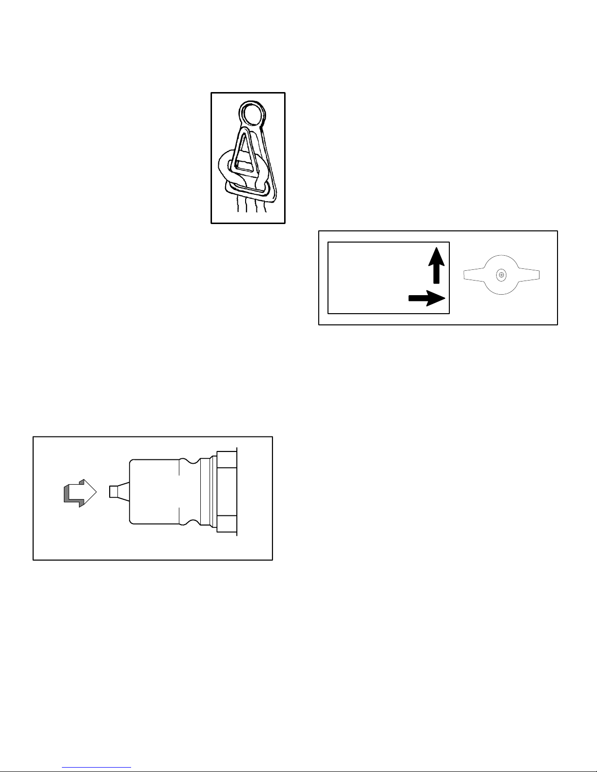
OPERATING THE ESCORT
NOTE: Vacuum the carpet and make sure it is cleared of sur-
face debris before starting the cleaning process.
NOTE: Pump Priming: If the machine has been in storage or
the pump runs dry – air entrapment within the solution line can
occur. This is alleviated by depressing the tip of the auxiliary
nipple momentarily while the pump is running.
Diagram 2
TO PRIME PUMP
The POWER ESCORT is easily adapted for use with the
following WINDSOR accessory tools; DHT–UPH3–SW–
SFW–SW/PRO
Diagram 3
o
ACCESSORY TOOL
CARPET SPRAY
NOTE: Turn machine off before connecting any accessory
tools.
1. Turn solution control valve from “Carpet Spray” to
accessory tool. (See Diagram 3.)
2. Remove recovery hose from dome and insert vacuum
hose for accessory tool in its place.
3. Attach solution hose from accessory tool to solution
outlet nipple on back panel of machine.
4. Make sure that sufficient amount of cleaning solution
is in solution tank and that the dome is in place and
ready for operation.
5. Turn on vacuum and continuous pump switches.
AUXILIARY
OUTLET
NIPPLE
Depress plunger with pump running.
Hold until pressure begins.
1. Dispense solution by using either the continuous flow
switch for cleaning smaller more confined areas. Switch
on power brush, depress pedal to Lower brush head
assembly. Walking backwards move the machine over
the area to be cleaned. Turn solution off about 8 inches
before the end of each pass to insure all solution is re–
moved from the carpet. When through cleaning depress
pedal to Raise brush head assembly. Switch off vac and
brush switches.
WARNING:
machine is not in cleaning mode. Damage to carpet could
occur.
2. As you work, check to see if there is a foam buildup
in the recovery tank. If there is a foam buildup, turn
the machine off and add the recommended amount
of a defoaming solution to the recovery tank.
Do not leave power brush running when
4
98255 7/1/97
CAUTION: Do not switch on power brush when us-
ing POWER ESCORT with accessory tools.
NOTE: Make sure the solution control valve is returned to
the “Carpet Spray” position before using POWER ESCORT for carpet cleaning.
DAILY/REGULAR MAINTENANCE
WARNING:
the machine, disconnect the power cord from electrical
source.
1. Empty unused cleaning solution from solution tank.
2. Inspect and clean filter screen in solution tank.
3. Flush pumping system with 1 to 2 gallons of clean
hot water.
4. After each use, rinse tank with fresh water. Periodically
inspect the recovery tank and decontaminate if necessary,
using a Hospital Grade Virucide or a 1–10 bleach to water
solution. Waste water should be disposed of properly.
5. Check spray jets daily for full spray pattern.
6. Check for and remove any debris or lint buildup from
vac shoe.
7. On power brush models remove lint and dirt buildup
from brush and housing.
Before making any adjustments or repairs to
Page 5

To Order Parts Call 1-888-702-5326 - https://monsterfloorequipmentparts.com
PERIODIC MAINTENANCE
Twice a month, flush a white vinegar solution (One quart vinegar
to two gallons of water) or anti–browning solution (mixed as
directed) through the POWER ESCORT This will prevent build–up
of alkaline residue in the system.
If spray jets become clogged, remove the spray tips, wash them
thoroughly, and blow dry.
NOTE: Do not use pins, wire, etc. to clean nozzles as this could destroy
spray pattern.
Apply silicone lubricant to solution nipple.
Periodically inspect all hoses, electrical cables, filters and con–
nections on your machine. Frayed or cracked hoses should be
repaired or replaced to eliminate vacuum or solution pressure
loss. Because the electrical cable must be well insulated and cable
connector screws kept tight, If the cable insulation is broken or
frayed, repair or replace it immediately. Don’t take chances with
electrical fire or shock.
3. To inspect motor brushes, remove brush holder assembly.
Brushes should be replaced when worn to 3/8 inch or after
about 250 operating hours. After second brush replacement
the armature commutator should be checked for pitting and
concentricity. Vac motors can be repaired but such repairs
should be made by a qualified motor repair shop.
VAC SHOE
1. Tilt machine back to rest on handle.
2. Remove (3) bolts holding shoe to tank.
(3rd bolt located at motor mounting plate.)
NOTE: When reinstalling a new vac shoe, proper alignment of
shoe to floor must be made.
1. Install vac shoe and tighten screws.
2. Set machine upright on a flat–level surface and check vac
shoe for level contact on the flat surface.
3. Make adjustment at axle leveling screws by tightening/
loosening both of the lock nuts until shoe is level.
3
TRANSPORT WHEELS
PROTECT FROM FREEZING
If it becomes necessary to store in temperatures that could drop below
40 F, the pumping system, hoses and valves must be protected from
freezing with a methyl hydrate window washer antifreeze solution. Do not use
ethylene glycol or cooling system antifreezes.
1. Add a gallon or two of window washer antifreeze to the supply
tank, turn on pump switch and spray until the antifreeze solution
fills the solution lines.
MAINTENANCE INSTRUCTIONS FOR
POWER ESCORT
WARNING:
source before making any adjustments or repairs to the
machine. Only qualified maintenance personnel are to
perform repairs.
Remove machine power cord from electrical
NOTE: In the following instructions all letter
designations, IE: will be shown in the up-
1
coming graphical examples in this guide.
TO ACCESS VAC MOTOR/ PUMP ASSEMBLY
Remove solution from both tanks.
1. SOLUTION TANK: Attach the 4 ft. vac hose, supplied with machine,
to dome. Switch on vac motor and vacuum unused solution into
recovery tank.
1. Remove screw and hub cap and slide wheel off
axle.. Before reinstalling wheel, clean axle and apply light
coating of silicone lubricant.
4
BRUSH ASSEMBLY / BEARING
1. Remove belt guard and “ROLL” belt off motor pulley.
2. Remove screw from each end of brush shaft and remove
brush assembly from housing. Replace brush or bearings as
required.
SWITCH CONTROL PANEL
1. Remove (2) screws holding switch housing to handle.
2. Replace switches as required.
CAUTION:
connected to proper terminals. Refer to wiring diagram located on
back panel (or owners guide) for assistance.
When replacing switches, make sure wire leads are
5
PUMP ASSEMBLY
POWER HEAD REMOVAL
2. Tilt machine back to rest on handle.
3. Remove cable from lift bracket.
Remove (2) pivot bolts.
4. Disconnect solution hose from elbow.
5. Remove (4) bolts holding pump/plate assembly to tank.
6. Lift out pump & plate assembly. Disconnect hoses from
pump and pump lead wires from junction box.
7. Refer to pump parts list for replacement parts.
7
6
8
2. RECOVERY TANK: Remove drain hose from keeper and empty
solution into bucket or floor drain.
VACUUM MOTOR
1. Remove (2) tank mounting bolts from rear chassis panel.
2. Lift up recovery tank to access vac exhaust hose. Disconnect
hose from vac motor, motor wire leads and remove tank/vac
motor.
2
1
98255 7/1/97
CAUTION: When replacing electrical parts refer to the machine
wiring diagram for proper connections.
CAUTION: When replacing hosebarbs on pump head– DO
NOT OVER TIGHTEN – as this could crack intake and
discharge ports in pump head.
5
Page 6

To Order Parts Call 1-888-702-5326 - https://monsterfloorequipmentparts.com
SOLENOID VALVE
If the machine continues to drip solution from the manifold after pump is
switched off check for: (A) Alkaline buildup in solution lines (B) Lint
or debris lodged in the solenoid valve.
1. Remove (2) Tank mounting bolts from chassis panel. Remove
recovery tank/vac motor assembly.
2. Remove left wheel to access valve retaining screws.
3. Remove in line solenoid valve:
Clean, repair or replace as required.
NOTE: The solenoid valve can be disassembled for cleaning when posi-
tive shut–off is interrupted and valve leaks through tee jets.
4. Remove hex nut at top of valve and lift off coil assembly.
5. Use spanner wrench or small punch and hammer to remove
plunger body. Remove lint and soap residue from plunger.
1
11
CAUTION: When r einstalling valve make sure arr ow is pointed in
the direction of solution flow.
BELT ADJUSTMENT
1. When servicing brush motor or brush assembly always check
belt for proper tension. The belt should be taut to prevent it
from slipping on cogged pulleys . To tighten belt, loosen motor
mounting nuts and rotate motor rearward just enough to tighten
belt.
VAC MOTOR EXHAUST FILTER
1. Remove (2) bolts holding chassis to tank.
2. Tilt machine back to rest on handle.
3. Remove hex nut from PVC muffler.
Repair or replace as needed.
POWER HEAD LIFT CABLE
1. Remove recovery tank/vac motor assembly.
2. Tilt machine back to rest on handle. Remove bolt holding cable
to lift bracket and (2) power head pivot bolts.
3. Remove guide pulley bracket assembly and remove from pulley.
4. Remove pedal and bracket assembly (4) screws. Replace cable as
required. Reinstall pedal assembly and power head assembly. To
adjust cable: Depress cable so that power head almost touches
vac shoe housing. Raise and lower power head with pedals to
make sure that the head will “Lock” in UP position when pedal
is depressed.
1
9
1
7
6
CHASSIS ASSEMBLY
Ref Qty. Part No. Description Serial No. Notes:
From To
1 41236 Hubcap, 5/8” shaft
2 89114 Wheel, 10” dia. 544841 –
3 70088 Screw, 10–32 x 1/2 PHMS
4 87016 Washer, #10 Star
5 57047 Nut, 1/4–20 Lock
6 57039 Nut, 1.5 NPT Flange
7 70020 Screw, 1/4–20 x 1/2 HHMS
8 87025 Washer, 1/4 Star
9 87013 Washer, 1/4 ID x 5/8 OD
10A 39028 Hose, 3/8 rubber x 13”
10B 39178 Hose, 3/8 rubber X 21.5 (Japan)
1 1 20042 Clamp, 3/8 Hose (D–slot)
12 40014 Hosebarb, 1/4MPT x 3/8
13 73239 Spacer, Valve
14 84003 Valve, 1 15V LP 2–Way Solenoind
15 50267 Label, Raise/Lower Brush
16 OPEN
17 62130 Plate, Pump
18 57081 Nut, 10–32 Captive J
19 65129 Pump, 115V 100 PSI w/Adv.
20 40033 Hosebarb, 1/4 MPT X 3/8 90D
21 40014 Hosebarb, 1/4 MPT X 3/8
22 70066 Screw, 10–32 x x 3/4 PHMS
23 54077 Muffler, Vac Exhaust
6
98255 9/15/97
Page 7

To Order Parts Call 1-888-702-5326 - https://monsterfloorequipmentparts.com
Ref Qty. Part No. Description Serial No. Notes:
From To
23 54077 Muffler, Vac Exhaust
24 20046 Clamp, 2.25” Worm Gear
25 39247 Hose, Vac Exhaust x 19”
26 39032 Hose, Hose, 3/8 Rubber x 15”
27 87015 Washer, 9/16 ID x 1.06 OD
28 56014 Nipple, 1/4 Close
29 40038 Hosebarb, 1/4 MPT x 3/8 45D
30 78156 Tee, 1/4 FPT
31 84065 Valve, 1/4 FPT Ball
32 56012 Nipple, 1/4 FPT QD
33A 50399 Label, L1500 Warning
33B 50577 Label, Warning/Caution – Japan
34 70091 Screw, 10–24 x 1/2 FHMS
35 73197 Strain Relief, 90 D
36 48028 Knob, Yellow Ball Valve
37 50540 Label, Valve position Symbol
38 34128 Frame, EBP–2 Main
39 03075 Axle, Wheel
40 70297 Screw, 1/4–20 x 1.5 Full Thd. HHMS
41 57104 Nut, 10–32 w/ Star Washer
42 39280 Hose, 3/8 Rubber X 8”
43A 50178 Label, Protect from Freezing
43B 50556 Label, Protect from Frz Japan
44 31016 Elbow, 1/4 NPT Street
45 70011 Scr, 1/4–20 x 5/8 HHCS SS
46 41281 Pump head asm., 115V pump
CHASSIS ASSEMBLY
27
44
A
28
11
26
11
87
20
19
46
18
17
9
8
H
11
*42
*11
7
*29
*14
8
*13
E
20
4
B
3
10AB
*11
*12
Items with an asterisk(*) are
used only on 115V machines
45
25
24
9
8
24
23
22
38
9
8
45
9
A
41
40
6
9
29
30
31
21
11
1
27
39
3
4
5
2
37
32
34
35
36
1
B
33AB
43AB
15
11
98255 9/15/97
7
Page 8

To Order Parts Call 1-888-702-5326 - https://monsterfloorequipmentparts.com
POWER BRUSH ASSEMBLY
38
39
23
24
34
16
15
41
25
42
29
28
39
40
38
40
6
39
28
38
43
45
46
44
37
36
27
35
49
50
16
77
26
51
15
15
32
48
52
33
47
32
48
7
30
31
12
47
56
10
55
53
57
36
40
54
38
39
H
38
39 40
58
38
39
40
30
75
69
61
62
82
65
64
59
72
60
71
66
67
69
63
71
Manifold Assembly
for 100V only
68
73
74
7
14
70
74
7
25
21
20
19
81
79 80
78
3
Ref Qty. Part No. Description Serial No. Notes:
1 53513 Motor, 115V DC Brush Drive
2 35071 Gasket, 1/8 x 1 x 5
3 87014 Washer, #8 Int Star
4 70052 Screw, 8–32 x 3/8 PHMS
5 62225 Plate, Assembly Motor
6 87018 Washer, #10 x 9/16 OD
7 57030 Nut, 10–32 Nylock
8 64035 Pulley , Motor, 3/8 Bore
9 70084 Set Screw, 8–32 x 3/16 KCP
10 1 1023 Belt, EPB2
22
4
See Manifold
note above
18
17
16
15
76
14
13
From To
11
10
9
8
9
7
6
1
2
5
3
4
8
98255 9/16/97
Page 9

To Order Parts Call 1-888-702-5326 - https://monsterfloorequipmentparts.com
POWER BRUSH ASSEMBLY PARTS LIST
Ref Qty. Part No. Description Serial No. Notes:
11 70118 Set Screw, 8–32 x 5/16 KCP
12 41142 Housing, EPB2 Brush
13 66095 Plug, 1/8 NPT
14 54116 Manifold, EBP2 Brush
15 70088 Screw, 10–32 x 1/2 PHMS
16 87016 Washer, #10 Star
17 20073 Clamp, 7/8 ID
18 04008 Adptr, 1/4MPT X 1.4FPT BR
19 40033 Hosebarb, 1/4 MPT x 3/8 90D
20 73323 Seal, EPR Brush
21 67140 Ring, Tolerance
22 62134 Plate, Belt Cover
23 67137 Ring, 7/8 Internal Snap
24 67138 Ring, 3/8 External Snap
25 09022 Bearing, EPB2
26 03047 Axle, EPB2 Brush
27 12012 Brush, EPB2
28 70177 Screw, 10–32 x 1/2 FHMS
29 64047 Pulley, Epb2 Brush
30 70218 Shoulder Bolt, 3/8 OD x 1/2 L
31 67029 Rectifier, Bridge
32 70066 Screw, 10–32 x 3/4 PHMS
33 87016 Washer, #10 star
34 70020 Screw, 1/4–20 x 1/2 HHMS
35 14280 Bracket, Brush Housing Lift
36 73220 Spacer, EPB2 Cable
37 27332 Cable, EPB2 Brush Lift
38 87013 Washer, 1/4 ID x 5/8 OD
39 87025 Washer, 1/4 Star
40 70190 Screw, 1/4–20 x 1/2 BHCS
41 57047 Nut, 1/4–20 Lock
42 14278 Bracket, Cable Roller
43 64034 Roller
44 73206 Spacer, .259 ID x 3/8 OD x 1/2
45 70018 Screw, 1/4–20 x 1 HHMS
46 62130 Plate, Pump
47 73208 Spacer, 3/4 OD x .208 Wht Nylon
48 57113 Nut, 5/16–18 Lock
49 73210 Spring, Pedal Release
50 70217 Shoulder Bolt, 3/8 OD x 1.25L
51 73219 Spacer, .57 OD x 3/4 L Nylon
52 66076 Pedal Assembly, Left
53 57005 Nut, 10–24 Hex
54 70223 Eyebolt, 3/16 w/ 10–24 Nut
55 66078 Pedal, Right
56 14275 Bracket Assembly, EPB2 Pedal
57 70216 Shoulder Bolt, 3/8 OD x 3/4 L
58 14277 Bracket, Right Hanger
59 57102 Nut, Strain Relief M 18,6
60 14276 Bracket, LeftHanger
61 14294 Bushing, 3/4 ID Snap
62 20056 Clip, Wire Self Adhesive
63 20035 Clamp, 7/16 Plastic Cable
64 57116 Nut, 6–32 w/ Star Washer
65 14020 Terminal Block, (3–4–3)
66 50267 Label, Raise/ Lower Brush
67 70210 Screw, 6–32 x 3/4 PHMS Blk Nylon
68 31016 Elbow, 1/4NPT Street
69 57106 Nut, 8–32 w/ Star Washer
70 40015 Hosebarb, 1/4FPT X 3/8
71 70012 Screw, 8–32 x 1/2 RHMS
72 34128 Framer, EPB2 Main
73 73168 Strain Relief, 1/2 NPT
74 84144 Valve, Check 0–800 PSI 1/4MPT
75 73195 Strain Relief, 1/2 NPT
76 57040 Nut, 1/2 NPT Conduit
77 70043 Screw, 10–32 x 1/2 PPHMS
78 44060 Jet, 8002, Mini Quick
79 44051 Jet Seal, Mini Quick
80 44052 Jet Body, Mini Quick
81 44054 Jet Asm, 80002 Mini Quick
82 20005 Clamp, 5/16 Dia. Plastic
From To
98255 9/16/97
9
Page 10

To Order Parts Call 1-888-702-5326 - https://monsterfloorequipmentparts.com
TANK ASSEMBLY
34
33A
38
68
36
35
F
39
32
19AB
18
20
46
53
45
66
52
37
51
44
23
J
43
49
40
5
42
41
54
50
55
56
C
57
F
60
61
33B
J
69
30
22
26
27
24
17
23
17
25
21
D
17
E
63
2
16
14
9
12
11
10
10
28
29
58AB
59
67
65
47
48
15
8
62
3
3
2
4
7
6
5
1
G
Ref Qty. Part No. Description Serial No. Notes:
1 73250 Strainer, 80 Mesh x 3/8 FPT
2 14076 Bushing, 3/8 MPT x 1/4 FPT hex
3 87015 Washer, 9/16 x 1.06 OD
4 56014 Nipple, 1/4 Close
5 75082 Tank, EPB–2 Solution
6 36055 Grommet, 1/2 ID x 1/4 Grrove
7 50379 Label, EPB–2 Main
8 31016 Elbow, 1/4 NPT Street
9 40015 Hosebarb, 1/4 FPT x 3/8
10 20042 Clamp, 3/8 Hose
From To
17
63
25
17
63
25
3
64
10
98255 11/13/97
Page 11

To Order Parts Call 1-888-702-5326 - https://monsterfloorequipmentparts.com
TANK ASSEMBLY PARTS LIST
Ref Qty. Part No. Description Serial No. Notes:
11 39243 Hose, 3/8 Rubber x 13.5
12 14258 Brush Set, 115V
13 OPEN
14 70191 Screw, 10–32 x 1/2 HHST
15 87016 Washer, #10 Star
16 70062 Screw, 1/4–20 x 4” HHMS 115V
17 87013 Washer, 1/4 ID x 5/8 OD
18 88220 Wire, 12” Ground (115V)
19A 53130 Motor, 115V 5.7” 3 Stage vac
19B 53183 Motor, 100V 5.7” 3 Sage Vac
20 73194 Spacer, Vac Mounting (115V)
21 35011 Gasket, Vac Motor Top
22 57039 Nut, 1.5 NPT Flange
23 57105 Nut, 1/4 w/ Star Washer
24 70018 Screw, 1/4–20 x 1 HHMS
25 70020 Screw, 1/4–20 x 1/2 HHMS
26 14264 Bracket, Vac Motor (115V)
27 27007 Cord, tank lid
28 51045 Lid, Solution Tank
29 39244 Hose, Drain x 14.5
30 20002 Clamp, 2” Nylon Ratchet
31 – OPEN
32 75083 Tank, EPB–2 Recovery
33A 78222 Tube Asm, Vac Stack
33B 04032 Adapter, 1.5 MPT x 1.5 FS PVC
34 31045 1.5 MS x FS PVC
35 34140 Filter, Vac Intake 10 Mesh
36 28029 Dome Assembly
37 35060 Gasket, S/C Dome
38 27274 Cuff, 1.5 Swivel Hose
39 39072 Hose Asm, 1.5 x 4” Vac Swivel
40 27167 Hose Cuff, 1.5
41 73505 Strain Relief
42 70085 Screw, 1/4–20 x 1/2 PHMS
43 72033 Switch, Momentary On–Off 115V
44 72004 Switch, Illuminated Rocker 115V
45 50271 Label, Control Panel (115V)
46 61167 Control Panel (115V)
47 72035 Switch, Curvette Lt Rocker (115V)
48 57040 Nut, 1/2 NPT Conduit
49 88470 Wire Asm, 115V
50 73195 Strain Relief, 1/2” NPT
51 57040 Nut, 1/2” NPT conduit
52 73322 Strain Relief, Cord hook
53 67147 Ring, 2” dia. split
54 23101 Cord Asm, 115V Pigtail
55 26009 Cord End, 115A 15A Fem–T–Lock
56 23086 Cord Asm, 115V 14/3 x 50’
57 26006 Cord End, 125V 15A 3–WIRE
58A 50272 Label, EPB wiring (115V)
58B 50645 Label, EPB2 100V W/O Sol
59 20035 Clamp, 7/16 Plastic cable
60 27079 Cuff, 1.5” White Hose
61 39230 Hose Assembly
62 20041 Clamp, 2.0” Worm Gear
63 87025 Washer, 1/4 Star
64 85021 Vac Shoe, Epb2
65 57132 Nut, Dress Panel 3/8–27
66 14622 Circuit Breaker, 1.5A (115V)
67 70088 Screw, 10–32 x 1/2 PPHMS SS
68 50775 Label, Warning Explosion Vert
69 50776 Label, Warning for Safety
From To
98255 11/13/97
11
Page 12

To Order Parts Call 1-888-702-5326 - https://monsterfloorequipmentparts.com
100 VOLT WIRING DIAGRAM
115 VOLT WIRING DIAGRAM
12
98255 9/16/97
 Loading...