

Page 1
POWER BRUSH
ESCORT
115V
(OBS)
Page
1
of
8
Models
ESWEPB
1
INDUSTRIES,
INC.,
1351
W.
Stanford
Ave.,
Enalewood,
CO
80110
USA
@
303/762-1800
FAX
303/762-0817
Page 2

Page
2
of
8
POWER
BRUSH
ESCORT
115V
(OBS)
INSPECTION
Carefuii un ack and inspect your
ex
-
tractor
kr
slippin damage. Each unit
is operated and
tforoughiy inspected
before ship ing and any damage is the
responsibil&
01
the carrier who should
be notified immediately.
ELECTRICAL
This extractor o erates on a standard
15
amp,
115
VOIPAC circult: Voltages
below
105
volts
or
above
126
volts could
cause serious damage to motors.
‘230
volt
50
hz model available.
WARNING:
Make sure you are using
the correct voltage as
speclfied on
nameplate before connecting machine
power cord to outlet.
GROUNDING INSTRUCTIONS
To protect the operator from electric
shock, this machine must be grounded
while in use. The machine is equipped
with an approved
threeconductor power
cord and three
-
prong grounding type
plug to
fit the proper grounding
t
e
re
-
ceptacle. The vacuum power corJgas a
plug as shown in Fi
.
A.
if a receptacle
connected to the
efectricai ground as
shown in Fi
A
is not available use an
adapter as
88own In Fig.
C.
The
ada ter
must be connected to an
eiectrrcai
ground in the electrical outlet, using
metal screw shown in Fig.
B.
wARN/NG:
To avoid electric shock,
use indoors only.
EXTENSION CORDS
if
an extension cord is used, the wire
size must be at least one
size
iar er
than the ower cord on the machfne
and must
ge
limited to
50
feet in length.
The ESCORT
Is equipped with a
50
ft.
14/3
power cord.
EQUIPMENT SETUP
NOTE:
Attach strain reiieflcord retainer
to power cord.
1.
Make loop in
power cord a
proximately
14’;
rom twist lock
receptacle end.
2
Slide cord loop
through slot in
retainer and over
retainer arm.
Pull
slack cord back
through slot
to
secure.
3.
Plug power cable from machine into
properly grounded
wail outlet.
4.
Using a clean container,
fill
solution
tank with hot water. The maximum
capaclty
of
the ESCORT is 7 gallons.
Mix in a nonfoamlng cleaning con
-
centrate for use in hot water extrac
-
tion machines at the proportions
noted on the container for various
carpet soil conditions.
NOTE:
When using a powder cleaner,
premix with hot water in clean
con-
talner before adding to solution tank.
OPERATING THE ESCORT
NOTE:
Vacuum the car et and make
sure
it is cleared of su&e debris be
-
fore starting the cleaning process.
NOTE:
Pump
Prlmfng:
If the machine
has been in
storage or the pump runs
dry
-
air entrapment within the solution
line can occur. This is alleviated b de
pressing the tip of the auxiliary nrppie
momentarily while the pump is running.
Depress
plunger with pump running.
I
Hold until pressure begins.
1
1.
Dispense solution
using either
the
continuous flow sw%ch
for
lay open
areas
or
the
intermlttent 8w toh for
amaiier
mom
confined
emas
ObSninR
if mac ine is equipped with ower
brush Switch on
power
brusR,
de
press pedal to
Loww
brush head
8s-
sembly. Waikin backwards move the
machine
over
tie area to k cleaned.
Turn solution
off
about 8 inchw
be
fore the end
of
each
paw
to Insure
ail solution is removed from the car
-
pet. When through oieanlng depress
edai to
Re-
brush head arrembly.
!i
witch
off
vac and brueh ewitches.
WARNING:
Do
not leave power
brush running when machine is not
in cleaning mode. Damage to
carpet
could occur.
2.
As you work, check to
see
if there is
a foam buiidu in the recovery tank.
if there is a
&am buildup, turn the
machine
off
and
add
the recommended
amount of a defoaming solution to
the recovery tank.
NOTE:
Never put defoamer in the
solution tank.
WARNING:
An overflow of foam
into the vacuum intake can damage
the
vac motor. Always
be
aware of
the waste water level in the recovery
tank. When the tank is about
three-
quarters full, turn
off
the machine, re-
move drain hose from keeper and
empty dirty water into bucket
or
floor
drain.
3.
When machine runs out
of
cieanln
solution , turn off the machine an!
refill the solution tank. Turn machine
on and continue cleaning process.
OPERATING THE ESCORT
WITH
ACCESSORY
TOOLS
The ESCORT can easii
be
adapted for
use with
Windsor hanJ tools and floor
tools.
ACCESSORY
TOOL
CARPET
SPRAY
NOTE:
Turn machine off before con
-
necting any accessory tools.
1.
Turn solution control valve from “car-
g.1 spray” to accessory tool.
(See
2
Remove recovery hose from dome
and insert vacuum
hose
for accessory
tool in its place.
3.
Attach solution hose from acco
tool to solution outlet nipple on bax
panel of machine.
4.
Make sure that sufficient amount of
cleaning solution is in solution tank
and that the dome is in place and
ready for operation.
6.
Turn on vacuum and continuous
pump switches.
iagram
3.)
CAUTION:
Do
not switch on
power
brush when using
ESCORT
with
~80ry
tools.
NOTE:
Make sure the soiutlon control
valve
is returned to the “car et
mrav”
wsition
before
usino
dFtT
for &r+t cleaning.
-
WARNING:
Before making any ad
-
justments
or
repairs to the machine
disconnect the
power
cord
from
ekctrka/
source.
1.
Emp unused cieanllrg solution from
soiutlbn tank.
2
inspect and clean filter screen in
solution tank.
3.
Flush pumping system with 1 to
2
gallons
of
clean hot water.
4.
Empty and clean recovery tank with
clean water.
6.
Checkspray
pattern.
jets
daily
for full
6.
Check for and remove any debris or
lint buildup from vac shoe.
7.
On power brueh models
remove
lint
and dirt build
-
up from brush and
housing.
PERIODIC MAINTENANCE
1.
Twice a month flush a white vinegar
soiution one quart vinegar to one
paiion of hot water) or an anti-brown-
ng solution mixed as directed)
through the
E$CORT. This will help
revent buildup of alkaline residue
P
n system.
2
if spray jete become clogged, remove
the spray tips, wash them throughiy
in vinegar and blow dry.
NOTE
Do
not use pins, wires, etc. to
clean jets as this
will
destroy spray
pattern.
2
Page 3
POWER BRUSH ESCORT
11
5V
(OBS)
Page
3
of 8
3.
4.
1.
Remove
(2
tank mounting bolts from
rear
chassls pcinsl. (Refer to Photo
3)
.
Remove recovery tanklvac moto;
if spray jets continue to drip after
solution ump Is turned off, the
so
-
ienoid vate will need cleaning.
(see
MAINTENANCE on Solenoid Valve.) rear chassis panel. assembly.
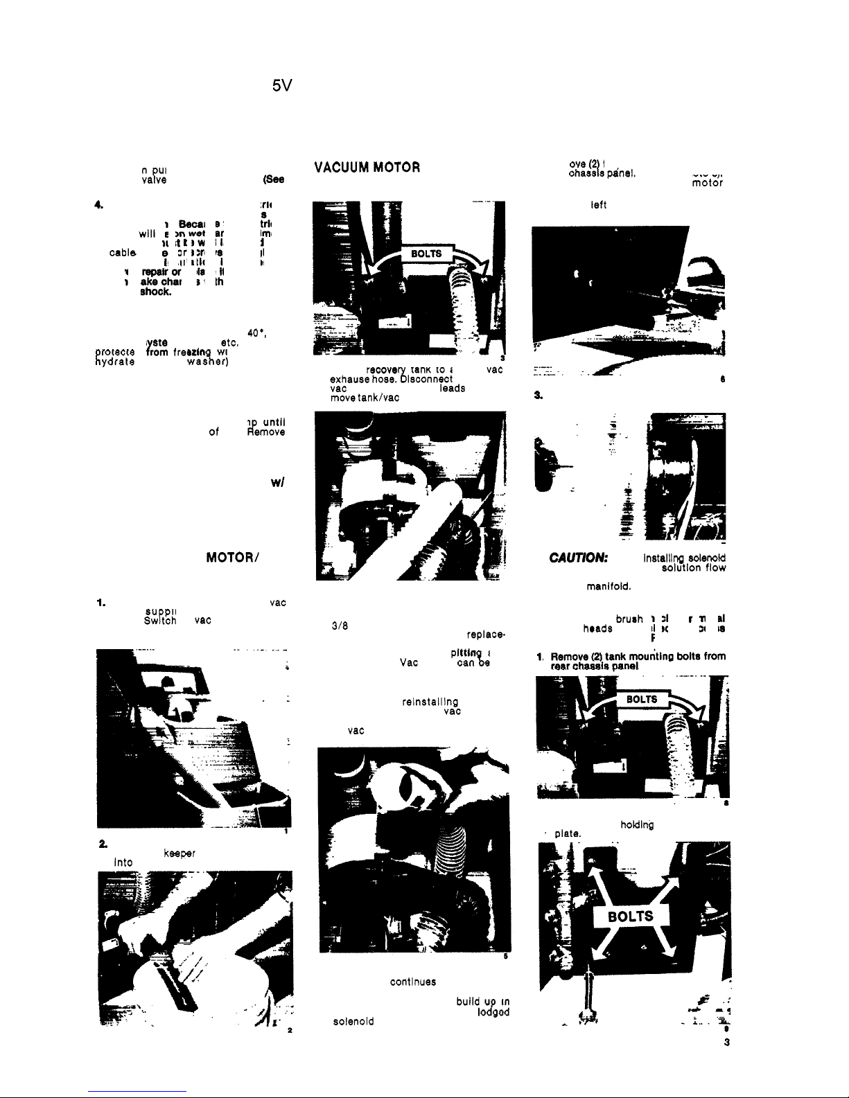
VACUUM
MOTOR
1.
Remove
(2)
tank mounting bolts from
Periodically inspect ail electrical
cables, filters and connections on
your machine. Because the electrical
cable
will lie on wet carpet at times,
the cable must be well insulated and
cabla connector screws kept tight. if
the cable insulation Is broken or
frayed, repair or replace
it
immediately.
Don't take chances with an electrical
fire or shock.
PROTECT
FROM
FREEZING
if it becomes necessary to store the
machine in temperatures below
40*,
the
pumping
s
stem, valves, etc. must be
rotected Lorn freezin with a methyl
Eydrate (window waster) antifreeze
solution.
NOTE:
Do
not
use
ethylene giycoie
or
cooling system antifreeze.
1.
Add window washer antifreeze to the
solution tank. Turn on pum
until
solution sprays out of jets. d'emove
unused portion of antifreeze from
tank.
MAINTENANCE INSTRUCTIONS
FOR
ESCORT AND
ESCORT
wl
POWER
BRUSH
WARNING:
Remove machine power
cord from electrical source before
making any repairs or adjustments to
the machine.
TO ACCESS VAC
MOTOR/
PUMP ASSEMBLY
Remove solution from both tanks.
I.
SOLUTION
TANK
Attach the 4 ft. vac
hose, su plied with machine, to
dome.
Swtch on vac motor and vac
-
uum unused solution into recovery
tank.
2.
RECOVERY TANK
Remove drain
hose from
keeper and empty solution
into bucket
or
floor drain.
2.
Lift up recove tank to access vac
exhause hose.%isconnect hose from
vac motor, motor wire leads and re
-
move tanklvac motor.
2
Remove left wheel to access valve
retaining screws.
6
3.
Remove iniine solenoid valve: Clean,
repair or replace a8 required.
7
4
3.
To inspect motor brushes, remove
brush holder assembly. Brushes
should be replaced when worn to
3/8
inch or after about
250
operating
hours. After second brush
repiace-
ment the armature commutator
should be checked for
pittin and
concentricity.
vac motors can%,
re
-
paired but such repairs should be
made
by
a quaiifled motor repair shop.
NOTE:
When reinstaiiina tanklvac
motor make sure the
vac recovery
hose is routed
ABOVE
exhaust horn
on
vac motor.
SOLENOID VALVE
if the machine contlnues to drlp solution
from manifold after pump is switched
off check for:
(A)
Alkaline build u in
solution lines
(B)
Lint or debris io&d
in solenoid valve.
CAUTION:
When instaiilng
edendd
valve make sure that solution flow
direction as indicated on valve Is
toward
manifold.
PUMP ASSEMBLY
NOTE:
On
power bruah machine removal
of brush
hrads is required to access
pump. (See Power Head Removal)
1.
Remove
(2)
tank mounting bolts from
rear chassis panel.
2
Lay machine on right side and re.
mow
(4)
bolts holding pump mounting
'
date.
Page 4

POWER BRUSH ESCORT
115V
(OBS)
3.
Disconnect pump motor wire leads.
Disconnect
solution
hoses
from
pump
head and remove pump. Refer to
pump drawlng
for
replacement parts.
10
CAUTION:
When reptactn hose
-
barbs on ump head
-
08
NOT
oVERn&N
-
as thls could crack
intake and discharge
~orts
in DumD
-.
..
head.
VAC SHOE
1.
Remove
(4)
bolts holding chassls and
pum plate to tanks. (Refer to Photos
2.
Remove
(3)
bolts hoidin vac shoe/
bracket to soiutlon
tan!. Repair or
reDlace as reaulred.
sas;
NOTE
When relnstalllng a new vac
shoe, proper alignment
of
shoe to
floor must be made.
1.
Install vac shoe and tlghten screws.
Attach chassis and pump plate as
-
sembly to tank and tlghten screws.
2.
Set machine upright on a flat-level
surface (a desk top works well) and
check
vac shoe for level contact
on
the fiat surface.
w
\
lllllll
4
VAC
SHOE
LEVEL
WITH
FLOOR
3.
Make adjustment at axle leveling
screws by tlghtenln
/loosening
both
of the lock nuts unti? shoe Is level.
TRANSPORT WHEELS
1.
Remove screw and hub cap and slide
wheel off axle. Before reinstalling
wheel, clean axle and apply
light
coating of silicone lubricant.
VAC
MOTOR
EXHAUST FILTER
1.
Remove
(4
bolts holding chassis to
tanks.
(Ref)er
to Photos
3
& 9)
2.
Lay machlne on side. Pull chassis
from tanks
to
expose exhaust muffler.
3.
Remove hex nut from
PVC
muffler.
Repair or replace as required.
1s
SWITCH CONTROL PANEL
1.
Remove
(2)
screws holdlng switch
housing to handle.
(EPB
housing
shown)
I
SCREWS
i
2.
Replace switches as required.
SERVICING POWER HEAD
BRUSH MOTORlRECTlFIER
1.
Tilt machine back to rest on handle.
2.
Remove
(6
screws holding motor and
plate to
houslng. Repair/repiace
motor rectifier as needed.
Page
4
of
8
BELT
ADJUSTMENT
1.
When servicing brush motor
or
brush
aseembly alwa
(I
check belt
for
proper
tension. The
LIt should
be
taut to
prevent it
from
sll
pin on cogged
pulleys. To tighten
Lit, pbosen motor
mounting nuts and rotate motor rear
-
ward lust enouah to tlahten belt.
BRUSHlBEARlNQ ASSEMBLY
1.
Remove belt guard.
2
Remove
screw
from
each
end
of brush
shaft and remove brush assembly
from housing. Replace brush
or
bear
-
rings as needed.
19
POWER HEAD
LIFT
CABLE
I.
Remove recovery tanklvac motor
assembly.
2.
Tilt machlne back to rest on handle.
Remove bolt holding cable to
lift
bracket and
(2)
power
head
pivot bolts.
4
Page 5

POWER BRUSH ESCORT
115V
(OBS)
Page 5 of
8
3.
Remove
guide pull bracket assembly
and remove
cableTom pulley.
21
4.
Remove pedal and bracket assernbl
(4
screws). Replace cable as requlred:
22
Reinstall pedal assembly and power
head assembly.
To
adjust cabic
Depress
cable
so
that power head almost touches
vac
shoe
houslng. Raise and lower
power head
with pedals to make sure
that head
will “lock”
In
UP posltion
when pedal
Is depressed.
POWER
HEAD
REMOVAL
1.
Tilt machine back to rest
on
handle.
Remove brush motor and plate
assembly.
(See
Photo 15)
2
Disconnect power cord from rectifier.
Loosen
strain
relief
and pull
cord
from
houslng.
(See
Photo 16)
3.
Remove cable from
lift
bracket and
(2)
pivot bolts.
(See
Photo
20)
4.
Disconnect solution hose from elbow
and
lay head
aside.
PUMP
ASSEMBLY
15
14
12.
WiRlNQ
DIAQRAM
EPB
CHASSIS ASSEMBLY
CONTROL PANEL END
MI#
CHASSISEND
A/-”
WlRlNQ
DIAQRAM ESC 115V
CHASSIS END
987
12
3
1
Q
15
I
CONTROL
PANEL END
PUMP
PARTS
LIST
w
CUTNO.
Duonicrwn
I
1
531 18 Molor 115V
(for
65067)
1A 531 19
Molor
230V
(for
65070)
2 67071
Rectifier/End
Bell
Asm.
3 47075
FanlShroud
Asm.
,
-
4-5-6 47076
Kit.
@se
Rat8
7g-911- 47087
Kll
Pum
Repair
(tor 65067
12
-
13
i
650!0)
10 27225
Bearing
Cover
14 41086
PumpHousing
15A 65071
Pump
Head
Asm.
115V
lfor
65067)
15B
65072
Pump
Head
Asm.
230V
(for
65070)
115/23OV
.
5
Page 6

POWER BRUSH ESCORT
115V
(OBS)
Page
6
of
8
POWER
BRUSH
ASSEMBLY
(EPB
Only)
m/";
I
fL\
66
1A
53146
MOW,
115V
Dc
msh
Drlw
I
19 62134
plate.
BSn
Wor
1
38
87013
WwhM.
114
ID x 5/8
00
I57
70218
ShoulduBoll.318ODx314L
I
39
87026
WMhU,
114St
158
14277
BRcM,R(ahtHulper
16
53147
MOIOT.
WOV
Dc
Brush
Oriw
I
20
31016
OW.
114
NPT
WWl
I
21
40014
Hasbarb.
114
MPT
x
3/8
I
40
70020
SCr.,
1/4-20
X
112
HHMS
I
!?
!?092
Nut.
5/18-18
LDCk
.
--
---
.-
..
.
.
.-
-
.
..
I
._
---.-
.. . _..
.
-I
,.__a__.
,_I
I,
_-_-_
2 - 35071
*!el,
I!!!!
x5
6
Page 7

POWER
BRUSH
ESCORl
r
I
15v
(OBS)
Page
7
of
8
TANK ASSEMBLY (ESWEPB)
37
35
39
Page 8

POWER BRUSH ESCORT
115V
(OBS)
CHASSIS
ASSEMBLY
(ESWEPB)
21'
I
Page 8
of
8
23
30
18 17na 16
I
ESWEPB
CHASSIS
I
WINDSOR
LIMITED
WARRANTY
WINDSOR warrants
to
the original
ur-
chaserluaar
that thm
prc&ct
M
frea
&in
defects in workmanship and materials
under normal
uae
and
senfloe
for
a
perlod
of
me
year
from
date
of
purchask WIND
SOR
will at its option repair
or
re lace
wthout
charge,
acepi
for
trnnsporl'etion
costs
parts that fail under normal
use
and hervice when operated and main
-
tained in accordance with the applicable
operation and instruction manuals This
warranty does not ap
ly
lo
normal wear.
or to items whose
iik
1s
dependent
on
their
use
and care, such as cords,
switches, hoses, rubber parts, electric
motor parts,
etc
Thls limlted warranty
is
in lieu
of
all other
warranties
ex
reased or im lied and
releases
WiNDgOR from all otler obliga
-
tions and liabilities
It
is appllcable only
in
the
U
8
A
and
Canada,
and
Is extended
only
to
the on inal userlpurchaser of
this
product WlhSOR is not
responsible
for
costs
for repairs performed by per
sons other than those specifically
authorized by WINDSOR This warranty
does not ap
ly
to
damage from frans-
portation aterattons by unauthorized
persons
inisuse
or
abuse
of
the equip
-
ment
u;e
of
noncompatible chemicals,
or
dimage
to
property or
loss
of income
due
to
malfunctionin~of the product.
If
a dilficulty develop8 with this machine,
you
should conlac1 the dealer from
whom it
wm purchased
dm
mn
INDUSTRIES,
INC.,
1351
W.
Stanford
Ave.,
Englewood, CO
80110
USA
303/782-1800
FAX
303/782-0817
 Loading...