

Page 1
ELECTRA-MATIC
1
15V
Page 1 of
26
Page 2
ELECTRA-MATIC
11
5V
Page
2
of
26
b
ELECTRA-MATIC
\
XI
\
\
\
\
I
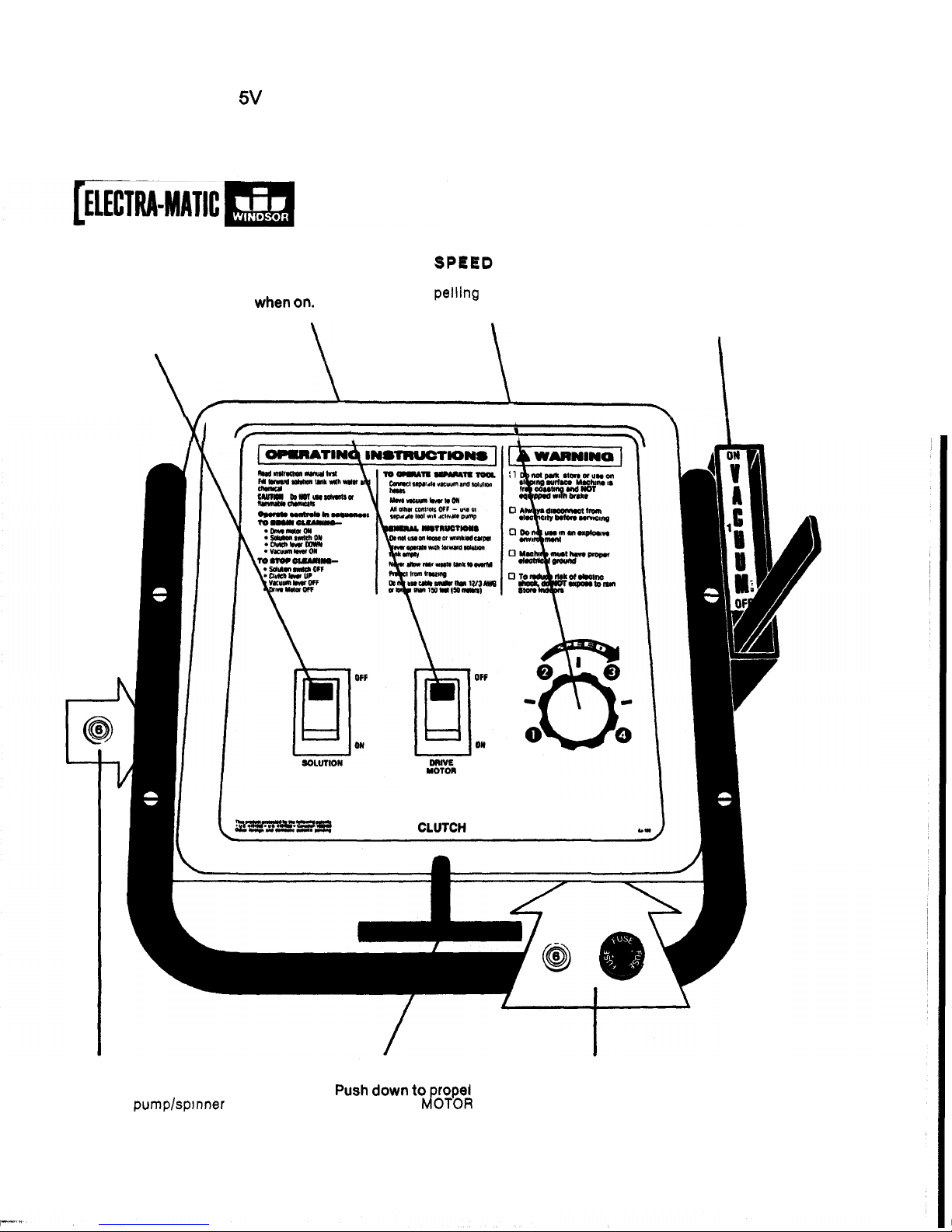
SOLUTION/ DRIVE
MOTOR
SPEJED VACUUM LEVER
THRUSTERJET
Turns on solution motor. Glows red pelling speed from
1
position to lower pickup
pump and THRUSTER
-
when
On.
(stop) to 4 (max.). assembly to carpet as
JET
drive motor.
Glows
red when
on.
motor.
Turns on propelling Control forward pro
-
Release to forward
well
as
start vacuum
\
\
THRUSTERJET CLUTCH DRIVE
MOTOR
LINE
FUSE
Protects pumplspinner drive
when
DRIVE
JOTOR
motor from burn-out. Push to
is
on.
reset after correcting problem.
CIRCUIT BREAKER
Push
down to rope1
AND CIRCUIT BREAKER
Protects drive motor and circuit board.
Replace fuse or push to reset breaker
after correcting problem.
Page 3
ELECTRA-MATIC
115V
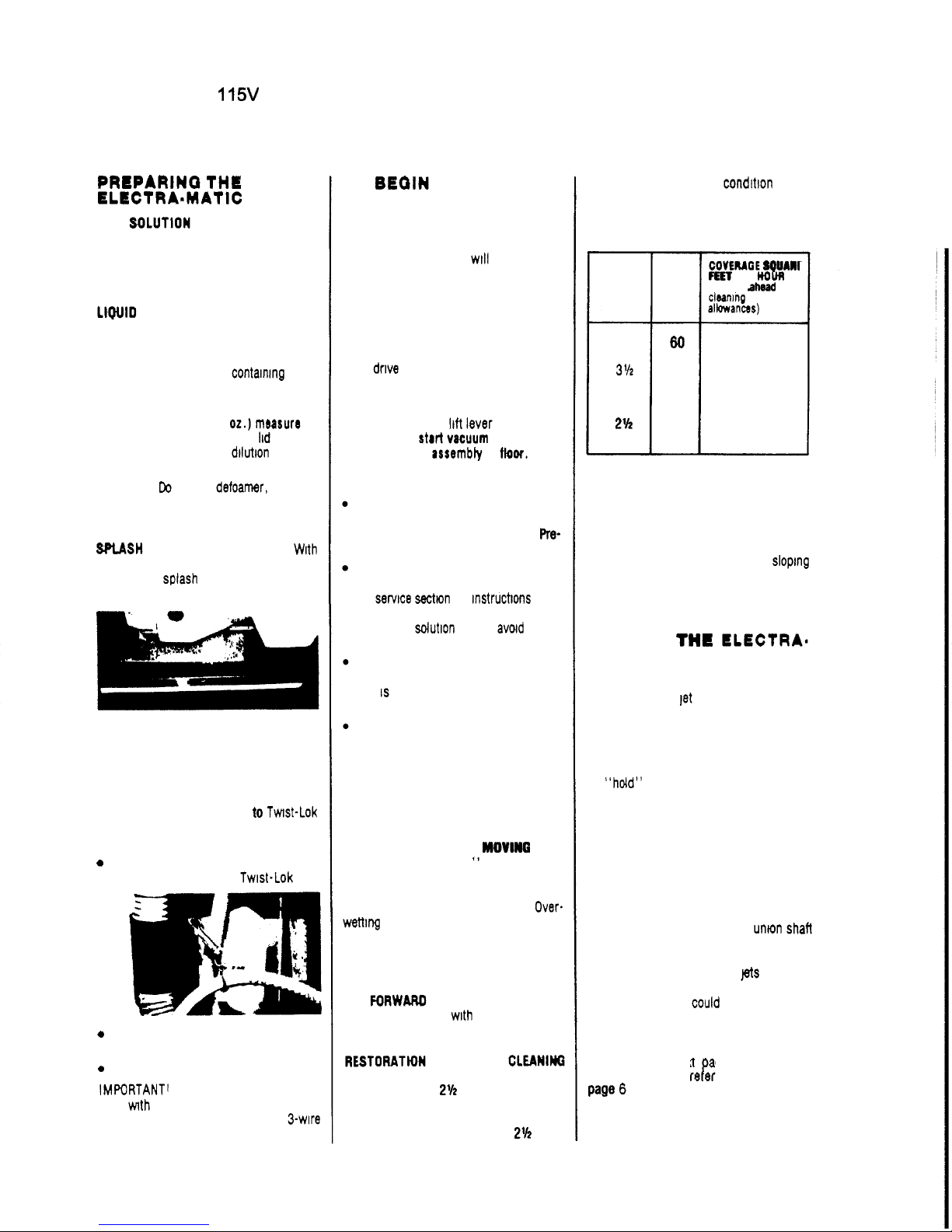
PREPARING
THE
FILL SOLUTlON TANK
to
the desired
level according
to
the marked gauge
inside the tank CAUTION‘ If a bucket
is used
to
fill the tank. be sure that it is
clean
however if a powdered detergent is used,
be sure it is fully dissolved
BEFORE
put
-
ting it in the solution tank
Do
this by
dissolving it in a bucket
contaning about
1
gallon of hot water before emptying it
into the solution tank
You will find a
1
cup
(8
02.)
mersure
on
the
bottom
of the solution tank iid
to
assist
you in making the proper
dilutlon
of
clean
-
ing chemical and water
CAUTION
Do
not
put defoamer. solvents,
spotter or prespray chemicals in the
solution tank
ELECTRA=MATlC
LIQUID
DETERGENTS ARE PREFERRED,
SPLASH
APRON ADJUSTMENT - Wah
machine setting on carpet
to
be cleaned,
adjust each
splash apron to touch top
of
carpet pile
PLACE RECOVERY DOME
atop recovery
tank, being sure that gasket material is
undamaged and making a good seal
with the recovery tank
ATTACH ELECTRIC CABLE
to
TWISt-LOk
connection
at
rear
of
control
panel beneath
operating handle
0
Note that all switches are in
“off”
position when attaching Twist-Lok
0
Attach cable strain reliever as shown
to
prevent electrical problems
0
Plug into grounded wall outlet
IMPORTANTI An extension cable may be
used
Hnth the ELECTRA-MATIC. however,
use nothing less than a
12
gauge, 3-Wire
of not more than
75
feet in length
TO
BEGIN CLEANING:
FOLLOW THE SEQUENCE BELOW.
.
.
1.
Set forward speed with control knob
2.
Press “drive“ motor switch
to
“on”
posdion
-
red light will glow
CAUTION Never turn on drive motor
with clutch lever down, damage to
motor and clutch could result
3.
Begin moving by pressing down on
clutch lever CAUTION Never secure
clutch lever in down position, damage
to
dnve motor and clutch could result
4.
Press thruster jet switch to “on”
position
-
red light will glow
5.
Release vacuum
lift
lever to forward
position
to
start
vacuum
motor,
and
lower
pkkup 8SSembly
to
fkw.
CLEANING TIPS
. . .
GO
SLOW
on very dirty carpet
to
avoid
streaking
Be
prepared
to
make two
cleanings
if
carpet is badly soiled
Pre-
spraying may also be necessary
Narrow bands
of
streaking can result
from a plugged THRUSTERJET nozzle
See
servlce sectlon for instructms Pay
more attention
to
using a clean bucket
when filling
solution tank to amd future
problems
Paths, or wide stripes. over the carpet
can occur with certain types of carpets
This
is due to the “lay”
of
the carpet
fibers
It
will go away when vacuumed
uncleaned stripe
Be
sure
to
overlap enough
to
prevent
WORK AWAY
from the power source
if
possible Begin cleaning next
to
wall
This will allow you
to
always make turns
away from the cable
KEEP ELECTRA-MATIC
MOVINO
when
thruster jets are “on
“
If
it becomes
necessary
to
stop
to
maneuver in a turn
or corner, push the thruster jet switch
to
the
“off”
position CAUTION Over-
wettlng
of
the carpet is likely. or damage
to
the carpet is possible,
if
the ELECTRA
-
MATIC is permitted to stand in one posi
-
tion with the thruster jets on
THE FORWAR0
SPEED
of
the
ELECTRA
-
MATIC
is
controlled mth the knob on the
control panel, numbered from
1
to
4
RESTORATW OR SALVAGE CLEANllsQ
will be best accomplished with the con
-
trol set from
1
to
2%
MAINTENANCE CLEANING
can
be
best
accomplished somewhere from
2%
up
to
Page
3
of
26
4,
depending upon the condition of the
carpel being cleaned.
Forward speeds and approximate cover
-
ages are
COVEMOE
SQUAnl
Far
PER
(Ioun
(Straight
ahmi
SPEED
clming
-
no
FPM
albwances)
4
60
5400
3%
43
3800
3
32
2800
2% 25 2250
TO PULL THE ELECTRA-MATIC
IN
REVERSE,
or
go
forward without power,
raise the pickup assembly by pulling
back on the vacuum motor lever
CAUTION: ELECTRA
-
MATIC is free
-
wheeling
It
should not be used
on
slopmg
surfaces or ramps Care should be
exercised when approaching walls,
obstructions or open stairways
TO
STOP
THE
LLECTRA-
MATIC:
FOLLOW THE SEQUENCE BELOW.
.
.
1.
Push thruster let switch
to
‘off”
2
to
3 feet before stopping
2.
Release clutch lever
to
bring ELECTRA
-
MATIC
to
complete stop
3.
Pull
vacuum
lever
backward
to
notched
“hold” position
4.
Do
not
push drive switch
“off”
unless
you are done working with machine for
the day or an extended period
It
is
preferred that the drive motor remain
on during brief periods
of
nonuse.
SPINNER
REMOVAL
To
avoid the possibility of the spinner
assembly seizing on the rotary
unm
shaft
due
to
alkaline buildup, remove spinner
at the end
of
each day The lets can be
removed
for cleaning Wash
pts
and blow
dry
Do
not use pins
or
wire to remove
obstruction as this
could
damage
jets
and
change spray pattern
To
remove
spinner,
tilt machine forward and remove spinner
assembly by turning counter clockwise.
(See
photo on next age). If spinner is
seized on shaft,
rekr
to
Photo
13
on
Page
6
3
Page 4
ELECTRA-MATIC
11
5V
Page 4 of
26
TO
USE
FLOOR
AND
HAND
TOOLS
wrth
the
ELECTRA-MATIC, attach solution hose
to male attachment at lower right rear of
machine, and the vacuum hose
to
the
clear plastic recovery
dome
Release the vacuum lever
to
the
forward
posfion
to
create
mum.
Solution
punp
turns on when valve at attachment
is
activated CAUTION. Switches on
ELECTRA
-
MATIC control panel must
remain
"
off
"
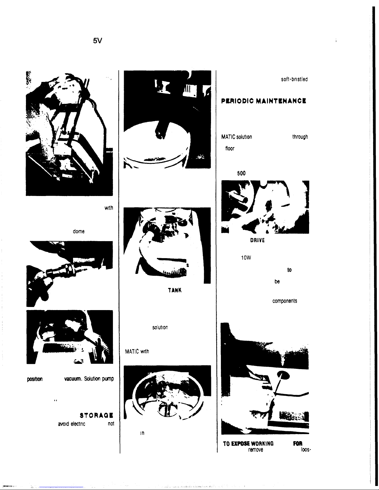
CLEANUP AND STORAQII
WARNING:
To
mid
electnc
shock
do
not
expose to rain. Store indoors
EMPTY RECOVERY TANK
directly into
floor drain
or
into bucket for disposal
Flush inside
of
recovery tank with clean
water Clean the inside of the recovery
dome
EMPTY
SOLUTION
TAnK
by detaching
recovery hose at floor
tool
and placing
into solution tank with vacuum motor
running
CAUTION Never allow recovered solutlon
to
remain in tank when not in use, nor
allow
unused solmon to remain in solutlon
tank when
in
storage
WIPE
the enbre outside of the ELECTRA
-
MATIC wrth a cleaning cloth. using warm
water and mild soap
STORE
ELECTRA-MATIC with recovery
shoe
in the "up" position Place
recovery dome upside down in recovery
tank
as shown
to
permit drying of
gasket
and the inside of the tank
INSPECT
screens in solutlon and
re
-
covery tanks Clean with soft-bristled
brush if necessary
PUIlODlC
MAlNTIINANCll
EVERY
TWO
WEEKS:
CLEAN
SOLUTION
SYSTEM
by diluting
2
gallons of clean water with a quart of
white vinegar (acetic acid) in ELECTRA
-
MATIC solution
tank
Run solutlon through
the system with the machine parked over
a
Hoor
drain
This procedure will
free
the
system
of
harmful buildups which could
eventually cause it to plug
EVERY
500
OPERATING
HOURS:
OIL FRONT ORlVE WHEEL BEARINGS
by removing hub cap and
snap
ring
on
axle Slide wheel off axle and apply
6
drops
of
1OW
oil
to
bearings
REMOVE VACUUM MOTOR
to
inspect
carbon brushes for wear
If
worn
to
3/8
inch, the brushes should
be
replaced
See
service section for instructions
WIPE
clean all working components when
exposed for vacuum motor inspection
TO
EX-
WORKING
PARTS
FOR
IN
-
SPECTION
remove inspection plugs,
100s-
4
Page 5
ELECTRA-MATIC
115V
Page
5
of
26
en screws holding tank support bracket
to
frame and
tip
tank assembly forward.
CAUTION:
Be
sure
ELECTRA-MATIC
IS
UNPLUGGED FROM WALL OUTLET AND
THAT TANKS ARE EMPTY.
TO REMOVE TANK ASSEMBLY
FROM
MACHIHE
disconnect internal
hoses,
pull
pins from front
hinges and tip
off.
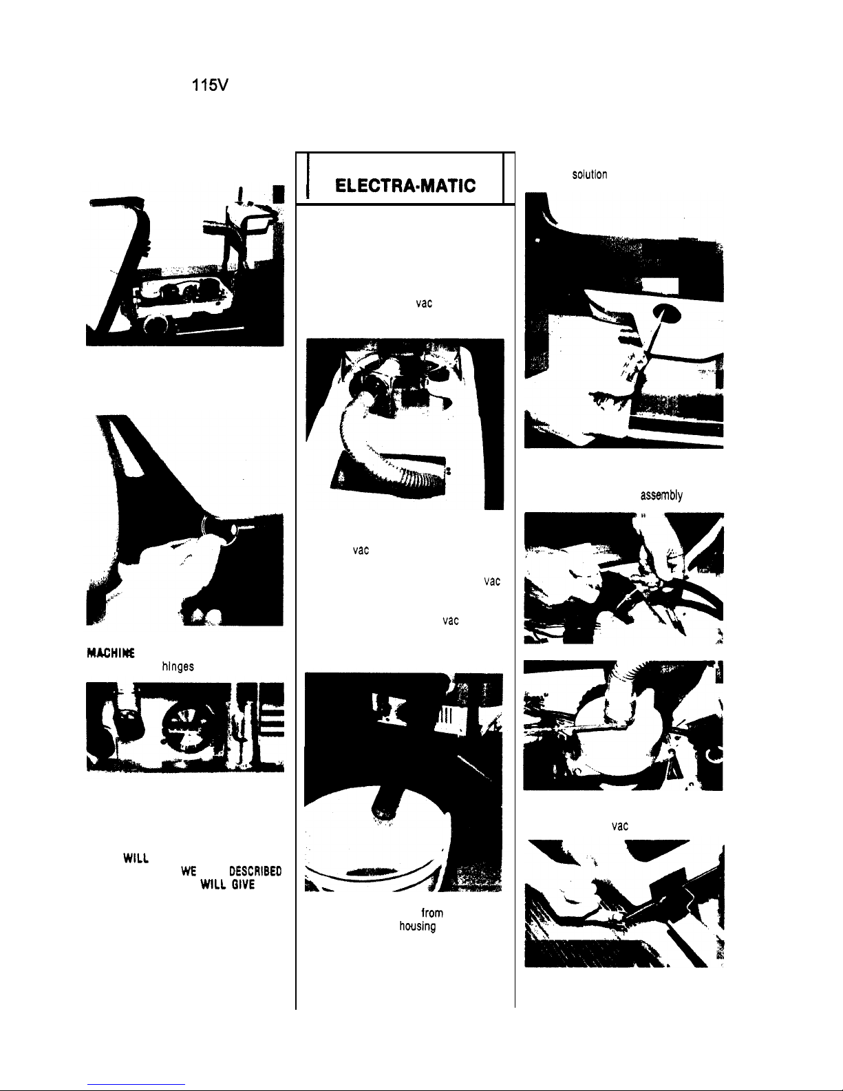
This digital recorder keeps track of
operating hours.
It
is wired into the
vacuum motor circuit
so
that all opera
-
tions using the vacuum are recorded.
IF
YOU
WILL
USE AND CARE
FOR
YOUR
ELECTRA
-
MATIC
AS
WE
HAVE
DESCRIBED
IN
THIS SECTION, IT
WLl
GIVE YOU
YEARS
OF
TROUBLE-FREE SERVICE.
SERVICING
THE
I
ELECTRA=MATIC
DRAIN AND CLEAN TANKS
SOLUTION TANK
-
(To remove unused
solution).
1.
Plug extension cable from machine into
2.
Remove hose from vac shoe and pull
properly grounded outlet.
through guide on handle
1.
3.
Position dome
on
waste water tank to
allow
vac hose
to
be lowered into
solution lank.
4.
Lower vacuum lever
to
turn on vac
motor. Vacuum solution into waste
water tank. Use water hose to rinse
inside
of
tank. Reattach vac hose to
shoe when finished.
WASTE WATER TANK:
2.
1.
Remove drain hose
from
keeper on
bottom
of control housing and put hose
over drain
or
bucket.
2.
Use
water hose and detergent
to
clean
inside
of
tank.
TANK REMOVAL
1.
Empty solution and waste water tanks.
3.
2.
Remove inspection plugs. Loosen
screws holding tank support bracket
to
frame
and
tip
tank
assembly
forward.
4.
5.
3.
Tilt
tank forward and disconnect hoses
from tank and
vac motor.
6.
4.
Remove front hinge pins and set tank
aside.
5
Page 6
ELECTRA-MATIC
1
15V
Page 6 of
26
lank
Repair:
The tanks are made
of
Polyethylene.
Small holes, cracks, etc., can be re
-
paired by using heat. Apply low
heat
from torch
to
damaged area
until
ma.
terial Is softened. Use screw driver
blade or other flat metal
tool
to
seal
damaged area.
TO
REINSTALL TANKS
1.
Set
tank in front
of
machine and in
-
2.
Connect solution and vac hoses.
3.
Lower tank
to
base
...
check position
of
hoses to make sure that they are not
pinched.
4.
Tighten screws to hold tank support
bracket
to
frame.
VACUUM
MOTOR
REMOVAL
1.
Disconnect machine power cord from
2.
To access vac motor, refer
to
"
Tank
stall hinge pins.
electrical source.
Removal
' '
instructions.
7.
3.
Disconnect hose from vac motor
exhaust.
8.
4.
Remove 3 screws holding vac motor.
R
9.
5.
Disconnect vac motor leads from
terminal block and remove
vac motor.
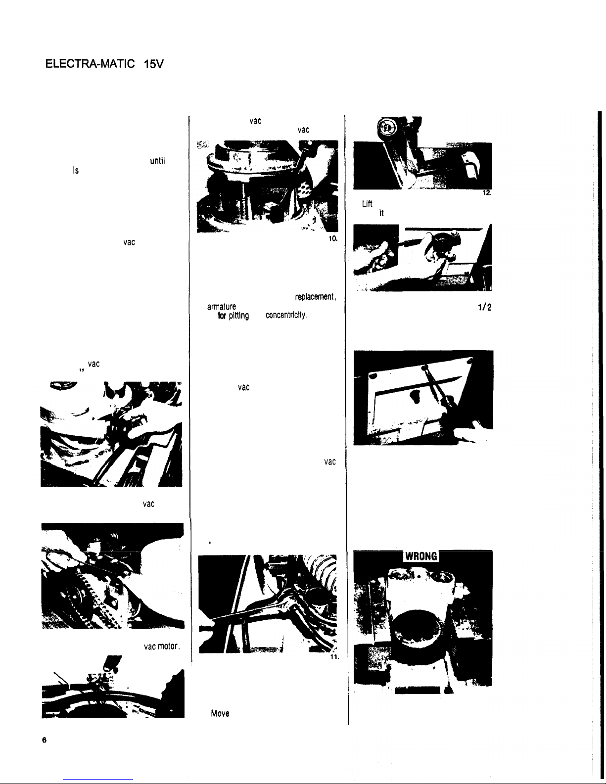
lo.
6.
To inspect motor brushes, remove
metal band around motor and remove
brush holder assembly. Brushes
should be replaced when worn
to
3/8
inch or after about
750
operating
hours.
After second brush
replacement,
armature commutator should
be
check
-
ed
for
pitting
and concentriciiy. Vacuum
motors can be repaired but such re
pairs should be made by a qualified
motor repair shop.
VACUUM
MOTOR
INSTALLATION
1.
Position vac motor on supports and
secure with screws and washers.
2.
Attach hoses
to
motor.
3.
Connect motor leads
to
terminal block
(refer
to
machine wiring diagram as
required.)
4.
Plug power cord from machine
to
properly grounded outlet and test vac
motor
by
lowering vacuum control
lever.
SOLUTION PUMP
REMOVAL
1.
Disconnect machine power cord from
2.
To access solution pump, refer
to
electrical source.
'
'Tank Removal" instructions.
3.
Remove hosebarbs from pump fittings.
(NOTE:
Special hosebarbs allow hose
to
swivel on barb during removal with
-
out damage
to
hose.)
4.
Move machine rearward slightly
to
position casters in rearward position.
5.
W
front of machine and
tilt
backwards
until
It
rests on the control handle.
13.
6.
Remove spinner assembly using
112
inch open end wrench
to
hold shaft
and turn spinner counterclockwise
(facing spinner).
14.
7.
Remove belt access cover.
8.
Loosen 3 nuts and screws that hold
pump
to
base and slide pump rearward
to
allow
belt
to
be
removed from pulley.
Remove nuts and screws and pump
from base.
SOLUTION PUMP
INSTALLATION
Page 7

ELECTRA-MATIC
1
15V
Page
7
of
26
1.
Remove elbows from old pump and
install on new pump using pipe
joint
sealant
CAUTION - if a vise is used to hold
pump, see photo for correct way to
clamp pump
Do
not overtighten vise
as this could
cause
Internal damage
to
pump.
Ekira
caution should
be
taken
to
keep
foreign
material lrom enterlng
pump
during assembly.
19
4.
Disconnect solenoid leads
from
terminal
5.
Use wrench
to
remove solenoid valve
6.
Clean, inspect or replace as required
ROTARY UNION AND SOLENOID VALVE
ASSEMBLY:
1.
heed as outlined in Steps 1 through
4 under “Solenoid Valve
“
2.
Lift front
of
machine and tilt backwards
until machine rests on control handle
(Photo 12)
3.
Remove belt access cover (Photo 14)
block and top of capacitor
from rotary union
2.
Install pulley
on
pump shaft at dimen
-
sion shown in Photo W17 (1 1/32 inch
between pump face and pulley flange)
3.
Set pump in position
on
main frame
and
Dut belt on Dujlev Install screws
and
nuts that hold pimp Slide pump
forward
to
tighten belt and tighten
pump mounting screws
4.
Install
belt
access cover, lower
ma
-
chine
to
Mor
and install tank
assembly.
Reinstall spinner assembly Put solu-
,I
-
-
tion in tank and test pumd
I
-
-
/I
I
ROTARY UNION AND/OR
SOLENOID VALVE
REMOVAL
SOLENOID
VALVE ONLY:
1.
Disconnect machine power cord from
2
To
access solenoid valve, refer
to
electrical source
“Tank Removal” instructions
3.
Remove hosebarb from solenoid (the
special push
lock hosebarb allows hose
to
swivel during removal without
damage to hose)
/
20
4.
Remove
belt
from rotary union pulley
(roll
off
being careful not
to
damage
belt)
22
5.
Loosen set screws
(2)
in pulley and
remove pulley from rotary union shalt
(use gear puller)
6.
Remove 3 screws holding rotary
unm
to
main frame
and
lift out solenoid
valve and rotary union assembly
7.
Inspect, repatr,
or
replace as
required
(Refer
to
rotary union breakdown for
replacement parts
)
ROTARY
UWlON
INSTALLATION
I.
Position rotary union on main nousing
and install mounting screws
23
2.
Slide pulley on shaft
to
dimension
noted and tighten set screws
(1
1/
16
inch between pulley and frame.)
3.
Install belt on pulley (roll belt onto
pulley
as
shown In
Photo
20).
If
belt
is
loose.
tighten by adjusting drive motor
or refer
to
“Belt
Adjustment“
in
-
structions
4.
Install belt access cover and spinner
assembly
5.
Lower machine
to
floor and install
tanks
6.
Put
solution
in
tank and test machine
BELT
REPLACEMENT!
ADJUSTMENT
I.
Disconnect machine power cord from
electrical source
2.
To access drive belts, refer
to
“Tank
Removal
’
’
instructions
3.
Lift front of machine and tilt backwards
until machine rests on control handle
(Photo 12)
4.
Remove belt access cover (Photo 14)
5.
Loosen motor mounting screws
(4)
and slide motor forward then remove
belt@)
7
Page 8
ELECTRA-MATIC 1 15V
Page
8
of
26
When installing new belts
use
tho
following sequence:
24
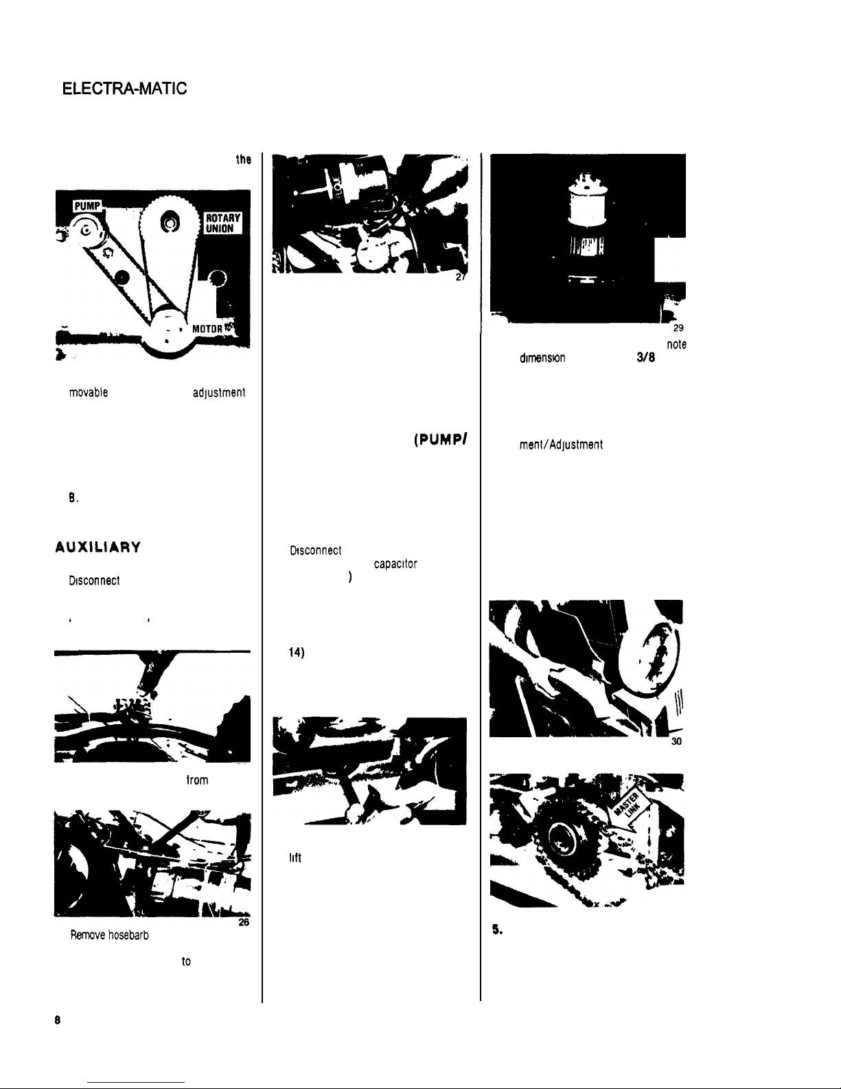
NOTE Drive motor and pump are
movable
to
allow for belt adjustment
Loosen screws holding pump and
motor
A.
Install pump drive belt then rotary
union drive belt Slide motor rear
ward until rotary union drive belt
is
tight Tighten motor screws
B.
Slide pump forward until drive belt
is tight Tighten pump screws
AUXlLlARY
PUMP
REMOVAL
1.
Dsconnect machine power cord from
2.
To access auxiliary pump, refer
to
electrical source
’
‘Tank Removal’ ’ instructions
25
3.
Disconnect pump leads from terminal
block
4.
Ranove hosebarb
at
branch
tee
(special
push lock hosebarbs allow hose
to
swivel without damage
to
hose during
removal and assembly)
5.
Remove 4 screws holding pump
to
frame and lift
out
pump
6.
Remove outlet hose with hosebarb from
pump head
7.
Lay pump on bench and refer
to
auxiliary pump breakdown for replace
-
ment parts
8.
Reinstall pump in reverse of Step
1
through 6 above
MOTOR
REMOVAL
(PUMP/
ROTARY
UNION
DRIVE
MOTOR)
1.
Disconnect machine power cord
from electrical source
2.
To
access dnve motor, refer
to
“Tank Removal” instructions
3.
Dtsconnect motor leads from ter
-
minal block and capacttor (Refer
to
Photo 25
)
4.
Lift front
of
machine and tilt back
-
wards until machine
rests
on
control
handle
(Photo
12)
5.
Remove belt access cover
(Photo
14)
6.
Loosen 4 screws holding motor
to
frame, slide motor forward and
re
-
move belts from motor pulleys
28
7.
Remove screws holding motor and
6.
Inspect motor, repair or replace as
lift motor
out
required
9.
When installing motor pulley, note
dimenstan
for
spacing
(1
38
inches
from face
of
motor
to
inside edge
of outer flange on pulley).
10.
Install motor in reverse of above
steps
11.
If
required, refer
to
“Belt
Replace
-
menVAdjustment
”
FRONT
AXLE
AND
WHEEL
ASSEMBLY
REMOVAL
1.
Disconnect machine power cord
from electrical source
2.
Remove tanks, refer
to
“Tank
Re
-
moval” instructions
3.
Remove belt access cover (Photo
12).
4.
Remove bottom splash guard
31
5.
Remove dnve cham
from
sprocket
NOTE:
Chain has master link for
easy removal
8
Page 9

ELECTRA-MATIC
1
15V
Page
9
of
26
32.
6.
Remove nuts and bolts holding
flange bearing
to
frame.
33.
7.
Remove axle assembly from machine
and put on workbench
to
service.
8.
Remove snap ring on each end
of
axle.
WHEEL
AND
AXLE
SERVICE/INSTALLATION
1,
Install flange bearings on axle. Po
-
sition set screws (in locking collars)
over innermost flats on axle and
tighten screws. (Slight adjustment
of bearings may be necessary when
reinstalling assembly
to
frame.)
2.
When replacing sprocket on axle
note dimension
-
approx.
3
5/16
from end
of
axle
to
face of sprocket.
(Photo
34)
34.
3.
Replacing bearing/clutch bearings
in wheels. These are directional
bearings and
must
be installed as
follows
:
35.
LEFT WHEEL:
Bearing must be
pressed in from
in
-
board side of wheel
with knurled end of
bearin sleeve on
inboar! side of
wheel.
36.
RIGHT WHEEL:
Bearing must be
pressed in from
outboard side of
wheel with knurled
end of bearing
sleeve on outboard
side of wheel.
NOTE: Both right and left bearinq assem
-
blies must be pressed in flush with the
inside
of
wheel hubs.
37.
1.
To check assembly: hold axle
-
each wheel should rotate forward
freely and lock on shaft when rota
-
tion is reversed.
TRAVERSE
DRIVE
MOTOR
AND
CLUTCH
REMOVAL
(Bodlne
Motor)
1.
Disconnect machine power cable
from electricat source.
2.
To access traverse drive motor, re
-
fer
to
"
Tank Removal" instructions.
38
39.
3.
Disconnect Molex connector from
motor and clutch lead connector.
4.
Remove chain. NOTE: Chain has
master link for easy removal
(Photo
31).
5.
Remove belt access cover
(Photo
12)
and
bottom
splash guard
(Photo
30).
40.
6.
fkmove 4 screws and nuts holding
motor and clutch
to
frame and re-
move motor. Put on workbench
7.
To
check motor brushes:
(utch
Wo
bottom
OI
kush
box
AS
UlOWN
Wng
R.Wnlng
Bnclut
Use
Long
NOW
Plkn for
R.mwsl
of
COns1sn1+we,
Roll-Type
Spring
Top
of
hsh.
Note
low
end
of
bewl
should
be
toward
spring
osvlty.
Brush
aspa
u.
hdd
In
@ace
wlth
maptypo
riwts.
Snap
bnah
orps
out using
irrgest
poeslbls
sow
drlver
tlp
undw
cap
owrheng.
Brush
Box
Tab
Alumlnum
Brush
Box
Page 10

ELECTRA-MATIC
1
15V
Page
10
of
26
BRUSH REMOVAL
(Bodlne
Motor)
41.
Brush
caps
are held
in
place with snap-
type rivets. Snap brush caps out using
large screwdriver
tip
under
cap
overhang.
Brushes are retained by constant
-
force,
d-type
springs. To remove springs, press
inward on the end of the spring retaining
bracket using the tip of a pair
of
long nose
pliers or other appropriate
tool.
Springs
should “pop”
out.
If
they don’t, they
can be removed by pulling outward on
the spring retaining bracket with a pair
of
long nose pliers. Brushes can now be
removed
by
pulling them out of the brush
boxes
by their “pigtails.”
It
is not neces
-
sary
to
rme the brush pigtail
dip
from
its connection to the brush box tab for
brush inspection.
BRUSH INSPECTION AND
CLEANINQ
(Ilodlne
Motor)
Brushes should be replaced
before
they
are
less
than
114
inch
(7
mm.) in length.
Carbon dust accumulation should be re
moved periodically. If the end shield has
been removed from the drive. a clean.
dry,
nonlinting cloth can be used
for
cleaning.
Do
not use solvents as they
may damage the nonmetallic end shield.
IMPORTANT
-
Make certain that the rdl-
type springs are positioned directly on
the brushes.
8.
The drive motor is equipped with
sealed ball bearings and does not
require lubrication.
9.
The gear
box
on traction drive motor
is grease
-
lubricated
to
last
tor
the
design life of the gear motor.
CLUTCH ADJUSTMENT
AND
SHRVICINd
(Electro Magnetic Clutch)
1.
Depending on the duty cycle and
load, periodic inspections of the
wear rate should be made. The air
gap
I
S
preset at the factory
to
.005/
010.
When this gap increases
to
,025
it
must
be
readjusted
to
factory
specs
(.005/.010).
42.
L3L.
To adjust, use a feeler gauge (of
spec. value) and turn the
(3)
set
screws
in
equally
to
close air gap.
When air gap can no longer
be ad
-
justed clutch must be replaced.
Care should
be
taken
to
insure that
dust,
dirt. oil. grease, soap, water.
etc. does not come in contact with
the working surfaces (rotor and
armature faces) of the
unit.
If fric
-
tion faces become dirty, the clutch
will slip, causing overheating and
a
loss
of
torque.
If
clutch fails to engage, check the
following:
A.
Check air gap: regap as required.
B.
Check for contamination of the
C.
Check electrical connections.
D.
Check for
grounded
or
open
coil.
Grounded
Coil: Disconnect ma
chine from power source. With
ohmmeter connected between
clutch lead and housing, there
should be no reading on meter
(check
both
clutch leads).
If
ohm
meter shows a reading, the coil
is grounded and clutch must be
replaced.
Open
Coil: Use ohmmeter
to
measure resistance
between
clutch leads. Reading on ohm
-
meter
should
be
775 i 40
ohm.
An
open coil indicates near
zero reading and clutch must
be replaced.
working faces.
TRAVERSE DRIVE
MOTOR
ANDCLUTCHREMOVAL
(Von
Welre
Motor
and
Marquette
Cluteh)
1.
Disconnect machine power cable
from electrical source.
2.
To access traverse drive
motor,
re
-
fer to “Tank Removal” instructions.
3.
Disconnect
motor
lead connector.
43.
4.
Disconnect leads from clutch arm
solenoid.
5.
Remove chain.
NOTE:
Chain has
master link for easy removal.
(Photo
31)
6.
Remwe
belt
access cwer
(Photo
12)
and
bottom
splash guard
(Photo
30).
7.
Remove
(4)
screws
and nuts hddlng
motor and clutch
to
main frame.
Remove motor and clutch and put
on work bench
to
service.
44.
8.
Remove brush cap and Inspect
motor brushes periodically. Brushes
should be replaced when
they
reach
318”
length or after approximately
750
operating hours. The gear
box
is
sealed
and
permanently
lubrkated
for
the life
of
motor.
CLUTCH ADJUSTMENT
AND
SERVICINQ
(Marquette
Mochankal
Clutch)
1.
Depending
on
the duty cycle
of
the
clutch, periodic inspections should
be
made.
10
Page 11

ELECTRA-MATIC
11
5V
Page
11
of
26
2.
Check
(2)
set screws located in
outer cogged clutch
rlng. If screws
loosen and back out, clutch slip
-
page will occur.
To
reset cogged
ring;
remove set screws from ring.
Rotate
rlng
to
align
set
screw hdes
in ring with corresponding hole in
metal clutch body. Using
allen
wrench install the
set
screws finger
tlght. CAUTION:
DO
NOT
owrlightsn
as
this will distort cogged ring and
cause
it
to
rotate
“out
of
round.”
46.
3.
Clutch actuator arm/solenoid ad
-
justment:
A
space of
1/16
to
3/32 must be
maintained between the tip
of
the
actuator arm and the cogged ring.
To
adjust, loosen the nut holding
eccentric spacer and rotate spacer
until proper adjustment is made.
Retighten nut
to
secure spacer.
VACUUM
SHOE
REMOVAL
47.
1.
Remove
lift
rod from casting (snap
spring connector).
48.
2.
Remove lower ball joint connectors
from
vac casting (snap spring con
-
nector).
3.
Use pliers
to
remove springs from
anchor screws.
4.
Loosen set screws that secure
shoulder
bolts
to
frame.
5.
Remove shoulder bolts that hold
upper link arms
to
frame and remove
vac casting.
6.
Repair as required and replace in
reverse of above steps.
VAC SHOE ADJUSTMENT
0-
.1w.
11#(1
rt
ri
n
no.
i
FIB.
I
m.
a
With machine on smooth level surface
the front and rear shoe of
vac casting
should be parallel with surface.
1.
If
front shoe is off floor (Fig. 3),
lengthen lower adjusting rods.
2.
if
rear shoe is off floor (Fig.
2),
shorten lower adjusting rods.
3.
Retighten lock nuts on adjusting
rods after completing
vac shoe
adjustment.
4.
Vsc
Shoe Height Adjustment-Place
machine on smooth level surface,
lower
vac shoe. Le-
.
ver should have
approximately
1”
of
additional forward
travel when properly
adjusted. Lengthen
or shorten lift rods
A
& B as required
(Fib.4).
CONTROL
BOX
REMOVAL
AND SERVICE
1.
Disconnect machine
power
cord from
electrical so~rce.
2.
Remove (4) screws and nuts hold
-
ing control
box
to
handle.
3.
Remove
(2)
screws
and nuts holding
upper and lower section of control
box together.
.
The following instructions pertain
to
identification and troubleshooting the
repairable components in the control box.
CAUTION: Repairs should only be at
tempted by qualified personnel since
damage can be done by persons not
experienced
in
working with printed cir
cuit boards and components. TeJting can
be
done with an ACIOC volt-ohmmeter.
TO
TEST SWITCHES AND
CIRCUIT BREAKERS
Remove them from machine and use an
ohmmeter or continuity tester. The correct
reading is zero for an
open
swltch/breaker
nuity) for a closed
switch/breaker.
QUULTCI)
and Infinity (conti
-
-~
THRUSTERJET/SPINNER
DRIVE
MOTOR
CIRCUIT
BREAKER:
If
circuit breaker trips after being reset,
check the following:
A.
Incorrect size
extensbn
cable
-
use nothing less than a 12
gauge, 3
-
wire of not more
than
75
feet In length.
B.
F#llty
pump/spinner drive
w.
C.
Plugged thruster jet)s).
0.
Faulty rotary unlon or pump.
E.
Faulty capacitor.
F.
Faulty circuit board.
11
Page 12

ELECTRA-MATIC 1 15V
TO
CHECK SPINNER
SPRAYPATTERN
Use
a commercial
low
pile
carpet
(a dark
color is preferable) to test spray pattern.
With solution in tank, activate solution
switch momentarily
to
roduce a "
suds
"
pattern on carpet. Tfie inside pattern
dbnrster
[Jet
#1) must
be
15%" to 16%"
The middle pattern
diameter
(Jet #2)
must
be
17%" to 1896". The outslde
pattern diameter (Jet
#3)
must be 18%"
to 19".
1.
SOLID STATE CLUTCH
CONTROL (DC CIRCUIT):
(Bodlne
PC
Board)
This control supplies
DC
current to clutch.
To check solid state control raise front
of
machine and use wood block
to
hold front
drive wheels
off
floor. Plug machine power
cord into properly grounded outlet. Turn
on drive
-
motor switch and depress clutch
switch lever.
If
clutch does not engage,
check voltages on octal socket. Voltage
at terminals
2
and 5 should
be
115
VAC
f
10% (on 115 volt models) and 230
VAC f 10%
(MI
230
vdt
models).
Vdt-
age
a!
terminals 4 and 7 should
be
90
to
110
VDC
f
10%.
If zero reading at
terminals
4
and
7,
replace solid state
control.
SOLID
STATE
CLUTCH
CONTROL (DC CIRCUIT):
(D8rt
PC Control)
This control supplies
DC
current to the
clutch.
To
check solid state control. raise
front of machine and use wood block to
hold front drive wheels
off
floor. Plug
machine
power cord into properly grounded
outlet. Turn
on
drive-rnotor switch and
depress clutch switch lever. If clutch does
not engage, check voltages at control
board. Voltage at terminals marked
AC
should be 115
VAC
-t
10% (on 115
volt models) and
230
VAC f 10% (on
230
volt models). Voltage at terminals
F-
and
F+
should be
85
to
105
VDC
f
10%. If zero reading at terminals
F
-
and
F+
replace solid state control.
SPEED CONTROL/
TRACTION DRIVE
MOTOR
(DC CIRCUIT):
(Bodlne Motor and PC Bo8rd)
12
The magnetic circuit breaker and in-line
(ceramic) armature fuse protects circuit
board and traction drive gear motor.
If
drlve
motor
does not
run,
check the
following:
1.
2.
3.
4.
5.
6.
7.
With machine ptugged in use
AC
volt meter to check input voltage at
terminals Ll
-
L2 (with drive-motor
switch on); reading should
be
115
VAC
2
10%
(on
115 volt models)
and 230
VAC
f
10% (on 230 volt
models). The output voltage at ter
-
minal A1 and A2 should
be
0-130
volts D.C.
Check for loose electrical connec
-
tions (at terminal block, switch,
motor P.C. board and receptacle).
Open
S-2
lead - use ohmmeter
to
check continuity from
speed
poten
-
tiometer to P.C. control board.
Check circuit breaker
for
continuity
(use ohmmeter). If breaker trips
after being reset, check for cause
-
faulty power cord
or
short In
cir
-
cuit. If this does not correct the
problem. the P.C. control board may
k
faulty.
Check in
-
line armature fuse
(2
amp
ceramic
fuse).
If blown, replace
with
(Iwc1
same
type.
If fuse blows
after being replaced, the gear
motor
may be grounded or short circuited.
To
test motor for ground or short
circuit, first disconnect machine
power cord from electrical source
then disconnect motor lead Molex
connector from motor. Using ohm
meter, check resistance between
each motor lead and the motor
frame. If readings are
inlnlty (con
-
tinuity), the armature is grounded;
replace gear motor.
To check for shorted armature, use
ohmmeter to measure the resistance
between the motor leads.
If
resist
-
ance
is
5
ohms
or
&,
the armature
is short
-
circuited: replace gear
motor.
If
motor
runs at maximum
speed
(no
speed
control), check leads S-1 and
S-3
for open circuit between speed
potentiometer and the
P.C.
control
board.
If
no open circuit is found,
the control board may be faulty.
Erratic starting and stopping
of
trav
erse motor could
be
due to a faulty
P.C.
board. With power connected
to machine and motor switch on,
Page
12
of
26
check
D.C.
output voltage at termi
-
nals
A1
and A2. If voltage does not
remain constant this is an indication
that
the P.C. board
is
shorted
or
open internally.
Replace
as
required.
SPEED CONTROL/
TRACTION
DRIVE
MOTOR
(DC CIRCUIT):
(D8rt
PC
Control)
The magnetic circuit breaker and in-line
(ceramic) armature fuse protects
arcuit
board and traction drive gear motor.
If
driw
motor
does
not
run,
check the
following:
1.
2.
3.
4.
5.
With machine plugged in use
AC
voltmeter
to
check input voltage
at
terminals
AC.
AC
(with drive
motor
switch on), readin should
be
115
VAC
f
10% (on 815 volt models)
and 230
VAC
f
10% (on 230
voll
models). The output volta e at ter
-
minals
A+
and
A
-
should&
0-105
volts DC.
Check for loose electrical connec
tions (at terminal block, switch,
and
P.C.
board).
Check circuit breaker for continuity'
(use ohmmeter).
If
breaker trips
after
being
reset,
check for cause-
faulty power cord
or
short in circuit.
If
this does not correct the roblem,
the P.C. board may be fau&y.
Check in-line armature
(2
amp
csramlc
fuss).
If
blown, replace
wilfi
exact
same
type.
If fuse blows
after being replaced, the
gear
motor
may
be
grounded or short circuited.
To
test for around or short circuit
tirst disconnect machine power
cord
from electrical source then discon
-
nect motor lead Molex connector
from
motor. Using ohmmeter, check
resistance
between each motor
lead
and the motor frame.
If
readings
are not infinity (continuity), the
armature is grounded, replace
gear motor.
To
check for shorted armature use
ohmmeter to measure the
resisdance
between the motor leads.
if
resis
-
tance is 5 ohms or less, the arma
ture is short circuited; replace gear
motor.
Erratic starting and stopping
of
trav
-
erse
motor could be due to a faulty
P.C. board. With power connected
to machine and motor switch on,
check
DC
output voltage at termi
-
nals
A+
and
A-.
If voltage does
not remain constant this is an in
-
dication that the
P.C.
board
is
shorted
or
open internally. Replace
as required.
Page 13

1-
I
LOWER
-
-
I
UPPER
CONTROL
BOX
CIRCUIT
(Bodin.
PC
Control
Boord
tW.21C)
w
115V WlRlNO SCHEMATIC
mw
LOWER
CONTROL
BOX
CIRCUIT
,
(lodin.
w
control
.owl
EII.21C)
uu
220V
WlRlNa
SCHLWATIC
UPPER
CONTROL
BOX
CIRCUIT
7
-
.IIp
220V WlRlNO SCHEMATIC
I-L
Page 14

ELECTRA-MATIC
1
15V
I
UI
VACUUM CIRCUIT
Page
14
of
26
ELECTRICAL
cin
(Bodlno
Motor
and
CLUTCH CIRCUIT
14
1-
Page 15

ELECTRA-MATIC
1
15V
Page
15
of
26
THRUSTER CIRCUIT
DRIVE
SYSTEM
CIRCUIT
15
Page 16

ELECTRA-MATIC
1
15V
Page
16
of
26
ELECTRICAL CIRCUIT IDENTIFICATION
(Bodlno Motor and PC Control
Board
EM-nlC)
TERMINAL
\
BOX
r
POWER
IN
GROUND
GROUNDING CIRCUITS EM-21 C
16
Page 17

ELECTRA-MATIC
115V
115V
WlRlNa SCHWATIC UPPER CONTROL
BOX
CIRCUIT
(Dart
PC
Control Board)
TO
115V
WIRING
SCHEMATIC
BASE
ASSEMBLY
(Dart PC Control Board)
101
Page
17
of
26
17
Page 18

ELECTRA-MATIC
11
5V
Page
18
of
26
ELECTRICAL
PARTS
IDLNTlFlCATlON
(Dort
PC
Contrd
mrd)
CIRCUIT MEAKER
1401s
CIRCUIT BREAKER
14027
P
SWITCH
72015
0
115VAC-
INLET
POWER
14017
[
4,"C VAC
smcn
mls
VACUUM CIRCUIT
(DWI
PC
DIIIT~lwAnO
1712s
11R
ma
t5ov
Control bard)
I
OROUNDINQ CIRCUITS
(Dart PC Control Wrd)
n
w
115VAC
INLET
WWER
1
pq
0-0
I
-
1,,
Page 19

ELECTRA-MATIC
11
5V
Page
19
of
26
CLUTCH CIRCUIT
(Dart PC Control Board)
d
I
1
--I
u
THRUSTER
CIRCUIT
[Dart
PC Control
bard)
1
DRIVE
SY8TLM
CIRCUIT
(Dart
PC Control
Board)
~
115VAC
INLET
4
I
lrn
Page 20

ELECTRA-MATIC
1
15V
1-
Page 21

A
A
Page 22

ELECTRA-MATIC
11 5V
53
73030
Skirt,
Front
I
54
31025
Elbow.
318"
45'St.
Page
22
of
26
EM-21
A
SOLUTION
/RECOVERY
TANK
22
Page 23

ELECTRA-MATIC
1
15V
EM-21C CONTROL PANEL BREAKDOWN
(Bodino
PC
Control
Board)
Page
23
of
26
23
Page 24

ELECTRA-MATIC
1
15V
CONTROL
PANEL
BREAKDOWN
(D8t't
Pc
Control)
Page
24
of
26
0--19
8-21
24
Page 25

ELECTRA-MATIC
1
15V
Page
25
of
26
EM-21
A
LOWER
SHROUDS
25
Page 26

ELECTRA-MATIC
11
5V
Page
26
of
26
~~
PUMP
PARTS
LIST
-
KEY
PlRT
NO.
DESCRIPTION
I
65018
65010
Pump and Motor Asm..
llOV
Pump and Motor Asm..
230V
1
53016
Motor,
115V
1A
53017
Motor.
230V
2
67066
Rectifier/End
MI
Asm.
3
62023
Plate, Motor Mounting
4
36006
Grommet
(set
of
4)
5-7-8-9
47015
Kit. Pump Repair
6
27057
Bearing
Cover
10
41010
Pump Housing
I1
72017
Pressure
Switch
12
65016
Pump Complete
47023
KIT, ROTARY
UNION
BEARING
?
47026
KIT, ROTARY
UNION
SEAL
26
PROBLEM
No
electrical power.
Loss
of
vacuum/
solution recovery.
No
forward movement
of machine.
No
solution flow.
Solution will not
shut
off.
Uneven cleaning.
TROUBLE=SHOOTINO
OUlDE
CAUSE
Dead electrical circuit.
Faulty main power switch on machine.
Faulty power cord.
Fuse-blown or circuit breaker tripped (on
machine).
iracuum lever in
"off"
position.
Faulty
vac motor switch.
Worn
vac motor brushes or faultv vac motor.
Crack in recovery dome
Obstruction or
damage in vac shoe linkage
or
vac hose.
Incorrectly installed or adjusted
vac
shoe.
Loose
wires at switch or connections.
Faulty drive motor switch.
Worn carbon brushes
in
gear drive motor
or faulty motor.
Fuse blown or circuit breaker tripped (on
machine).
Faulty speed control potentiometer.
Faulty pump drive motor.
Faulty pump.
Broken pump drive belt
Faulty switch.
"
Clogged" or faulty solenoid.
Obstruction in thrusterjets.
Faulty thruster control switch.
Dirt in solenoid valve or faulty valve.
One or
more thrusterjets plugged.
Broken rotary union
drive belt.
SOLUTION
Check building circuit breaker or fuse box.
Replace switch.
Repair or replace power cord.
Replace fuse or reset breaker after correcting
problem,
Put lever in
"on"
position.
Replace swltch.
Replace motor brushes or motor.
Repair or replace.
Remove obstruction, repair or replace
vac
casting.
Adjustvac shoe.
Repair as required.
Replace switch.
Repair or replace motor
Rplace hose or reset breaker after correcting
problem.
Replace control.
Repair or replace motor
Replace pump.
Replace belt.
Replace switch.
Remove obstruction or replace.
Remove spinner assembly and clean
jets.
Replace switch.
Remove obstruction or replace valve.
Remove spinner assembly and clean
lets.
Replace belt.
 Loading...