

Page 1
COMMODORE
1
15V-98048
Model
CMD
I
INDUSTRIES, INC., 1351
W.
Stanford
Englewood.
CO
80110
USA
FAX
Page 2

COMMODORE 115V
IMPORTANT
SAFETY
INSTRUCTIONS
When using an electrical appliance, basic precautions
should always be followed, including the following:
Read all instructions before using this machine.
This machine
is
for commercial use.
SHOCK,
OR
INJURY:
TO
REDUCE
THE
OF
FIRE, ELECTRICAL
A
1.
Do not use outdoors or expose to rain.
2.
Machines can cause a fire when operated near flam
-
mable vapors or materials.
Do
not operate this machine
near flammable fluids, dust, vapors or gas.
Do
not pick
up burning materials such as cigarettes or matches.
3.
Do
not leave the machine unattended. Unplug machine
from power outlet when not in use.
4.
Switch off switches before disconnecting power cord
from electrical outlet.
Maintenance and repairs must be done by qualified
personnel.
6
Do
not disconnect cord from outlet by pulling on cord.
Grasp plug to remove from outlet.
Do
not use power cord as a handle, close door on cord,
or pull cord around sharp edges or corners.
8
Do
not
operate machine with any openings blocked.
Keep openings free of debris that may reduce air flow.
Do
not use machine as a step or operate machine
unless
it
is completely assembled.
SAVE
THESE
INSTRUCTIONS
Page 3
COMMODORE
1
[COMMODORE
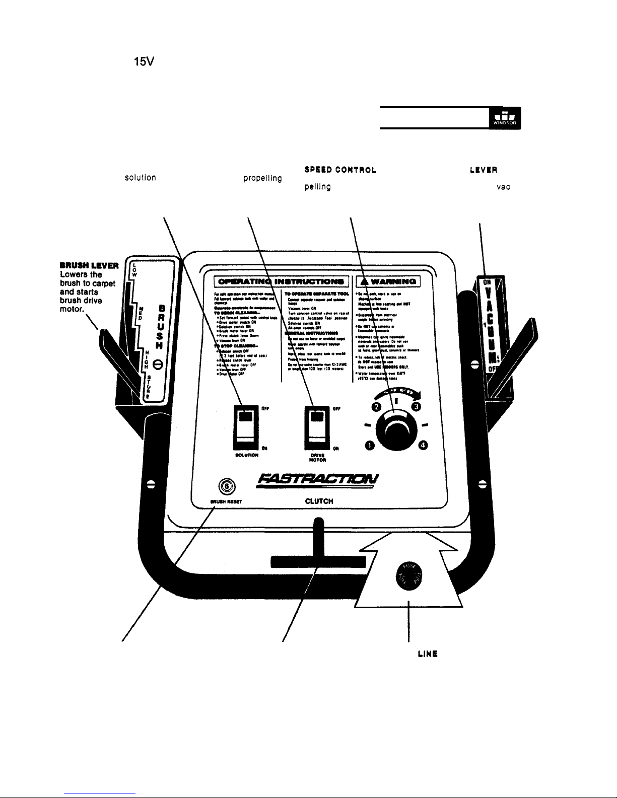
SOLUTION
SWITCH
DRIVE
MOTOR
Turns on solution pump.
Turns
on
Controls forward pro
-
Release to forward
Glows red when on.
motor. Glows red
when on. stop to 4 (max.). shoe assembly to
carpet as well as start
\
\
\
vacuum motor.
CIRCUIT
BREAKER
Protects brush drive
motor from burn
-
out.
Push to reset after
correcting problem.
CLUTCH LEVER
Push down to propel
when
DRIVE
MOTOR
is on.
DRIVE
MOTOR
Protects drive motor and circuit board.
Replace fuse after correcting problem.
3
Page 4
COMMODORE
THE
COMMODORE
FILL SOLUTION TANK
to
the desired
to
the marked gauge
inside the tank.
CAUTION:
If a bucket
used
to
fill the tank, be sure that
it
Is clean.
CAUTION:
To avoid oossible distortion
of polyethylene
DO NOT
USE
WATER TEMPERATURE
THAT EXCEEDS
150°F
(65°C).
PREFERRED,
however if a powdered detergent is
used, be sure
it
is fully dissolved
BEFORE
putting
it
in the solution tank.
Do
this by dissolving it in a bucket
containing about
1
gallon of hot water
before emptying it into the solution tank.
You will find a
1
cup
(8
measure
on the bottom of the solution tank lid
to
assist you in making the proper
dilution of cleaning chemical and water.
WARNING:
Do not put defoamer.
solvents, spotter or prespray chemicals
in the solution tank.
CHEMICALS
The internal parts
of
the pump used in
the extractor is suitable for use with
most carpet cleaning chemicals. But it
is susceptible
to
chemical attack from
some cleaning substances, such as
hydrocarbon solvents and chlorinated
are not of the type normally used for
carpet cleaning,
SUITABLE
CHEMICALS CHEMICALS
Aldehydes
Clomx
Bleach’
Hydrocarbons
Agents
But
Detergents
Tetrachloride
Hydroxides
Oxygen
Bleaches
Chlorinated
Bleaches
soaps
Chlorinated
Hydrocarbons
Softener’
1
Vinegar
(MEK)
White
Monday
Bleach’
Phenols
PLACE RECOVERY DOME
atop recovery
tank, being sure that gasket material
is undamaged and making a good seal
with the recovery tank. Connect hose
from
to
dome.
1.
4
ATTACH ELECTRIC CABLE
connection at rear of control panel
beneath operating handle.
.
Note that all switches are in
“off”
position when attaching Twist-Lok.
.
Attach cable strain reliever as shown
to
prevent damage
to
power cord
connections.
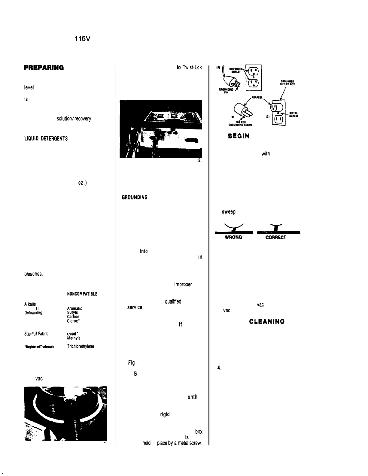
This appliance must be grounded. If
it
should malfunction or breakdown,
grounding provides a path of least re
-
sistance for electric current
to
reduce
the risk
of
electric shock. This appliance
is equipped with a cord having an
equipment
-
grounding conductor and
grounding plug. The plug must be
plugged
is
properly Installed and grounded In
accordance with all local codes and
ordinances.
WARNING;
-
nection
of
the equipment-grounding con
-
ductor can result in a risk
of
electrical
shock. Check with a
electrician
or
as
to
whether the outlet is properly
grounded.
Do
not modify the plug pro
-
vided with the appliance
-
it
will not
fit the outlet, have a proper outlet in
-
stalled by a qualified electrician.
This machine is for use on a nominal
120
-
volt circuit, and has a grounded
plug that looks llke the plug illustrated
In
A.
A
temporary adapter that
looks like the adapter illustrated in
Figs.
and C may be used
to
connect
this plug
to
a 2-pole receptacle as
shown in Fig. B if a properly grounded
outlet is not available. The temporary
adapter would be used only
a
properly grounded outlet (Fig.
A)
can
be installed by a qualified electrician.
The green colored
llke extending from the adapter must
be connected
to
a permanent ground
such as a properly grounded outlet
cover. Whenever the adapter Is used,
it
must
be
in
TO
CLEAWINQ:
FOLLOW THE SEQUENCE BELOW.
.
.
1.
Set
forward speed with control knob.
2.
Press
“drive” motor switch
to
“on”
position. Red light will glow.
3.
Press “solution” switch
to
“on”
position. Red light will glow.
4.
Release “Brush Motor Lever”
to
“on” position and adjust brush
to
correct cleaning height. The brush
setting Is correct when the bristles
the surface of the carpet.
NOTE:
Starting the machine with
dry bush resting on the carpet may
trip circuit breaker.
5.
Press down on clutch lever
to
start
forward movement.
WARNING:
Do
not secure clutch lever
in “down” position. Damage
to
machine could occur.
6.
Release vacuum lever
to
“on”
position
to
start vac
motor
and
lower
to
carpet.
TO
STOP
FOLLOW THE SEQUENCE BELOW
.
.
.
1.
Push solution switch
to
“off”
(2
or
3
2.
Release clutch lever.
3.
Lift brush lever
to
“off” position.
Lift vacuum lever
to
“off”
position.
5.
Push drive motor switch
to
”off”
position.
WARNING:
The drive train of the
COMMODORE is
FREE WHEELING
and the machine should not
be
left
unattended or used on sloping sur
-
faces or ramps.
feet before end
of
pass.)
TO PULL THE COMMOOORE IN RE
-
VERSE,
or go forward without power
...
first raise vacuum and brush levers
to
“off”
position.
’
Page 5
COMMODORE
1
15V
CLEANING TIPS
.
.
.
GO
SLOW
on very dirty carpet
to
avoid streaking.
prepared
to
make
two cleanings if carpet
is
badly
soiled. Prespraying may also be
necessary.
Narrow bands of streaking
can
result
from a plugged nozzle. See service
section for Instructions. Pay more
attention
to
using a clean bucket
when filling solution tank
to
avoid
future problems.
Paths, or wide stripes, over the
carpet can occur with certain types
of
carpets. This is due
to
the “lay”
of the carpet fibers.
It
will go away
when vacuumed.
Be
sure
to
overlap enough
to
prevent
uncleaned stripe.
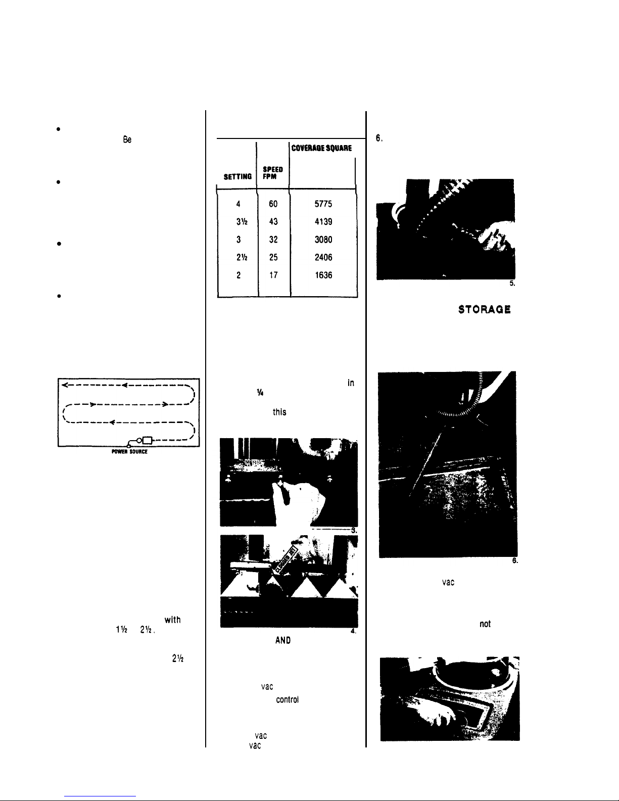
WORK AWAY
from the power source
if
possible. Begin cleaning next
to
wall.
This will allow you
to
always make
turns away from the cable.
KEEP
THE MACHINE MOVING
when
jets
are “on.” If
it
becomes necessary
to
stop
to
maneuver in a turn or corner,
push the solution switch
to
the
“off”
position.
CAUTION:
Overwetting of the
carpet
is
likely,
or
damage
to
the carpet
is possible, if the COMMODORE is
permitted
to
stand in one position with
the jets or brush on.
THE FORWARD SPEED
of the COM
-
MODORE
is
controlled with the knob on
the control panel, numbered from
1
to
4.
RESTORATION
OR
SALVAGE CLEANING
will be best accomplished with the
control set from
to
MAINTENANCE CLEANING
can be best
accomplished somewhere from
up
to
4,
depending upon the condition of
the carpet being cleaned.
Forward speeds and approximate
coverages are:
I
I
FEET
PER HOUR
(Straight ahead
SPEED
cleaning - no
FPM
allowances)
I
SPRAY
JETS
To prevent clogged jets due
to
alkaline
build
-
up, the spray system should be
flushed with
2
or
3
gallons of clean hot
water at the end of each day. The
COMMODORE
is
equipped with “quick
change”
jets
that can be easily removed
for cleaning. To remove
-
push jet
and rotate
turn. Wash jets and blow
dry.
Do
not use pins or wire
to
remove
obstruction as
pattern.
TO USE FLOOR AN0 HAND TOOLS
with
the COMMODORE:
1.
Attach auxiliary solution hose
to
outlet nipple.
2.
Connect vac hose
to
recovery dome.
3.
Turn solution control valve
to
“acces
-
4.
Press pump switch “on.“
5.
Lower vac lever
to
“on”
position
to
sory
tool”
position.
start
WARNING:
All
other switches on
control panel must remain
“OFF.”
Make sure solution control valve is
returned
to
“carpet spray” position
before using the COMMODORE for
self
-
contained carpet cleaning.
CLEANUP AND
EMPTY RECOVERY TANK
directly into
floor drain. Flush inside
of
recovery
tank with clean water. Clean the inside
of the recovery dome.
EMPTY SOLUTION TANK
by detaching
recovery hose at
into solution tank with vacuum motor
running.
CAUTION:
Never allow recovered solu
-
tion
to
remain in tank when not in use;
nor allow unused solution
to
remain in
solution tank when in storage.
7.
5
Page 6
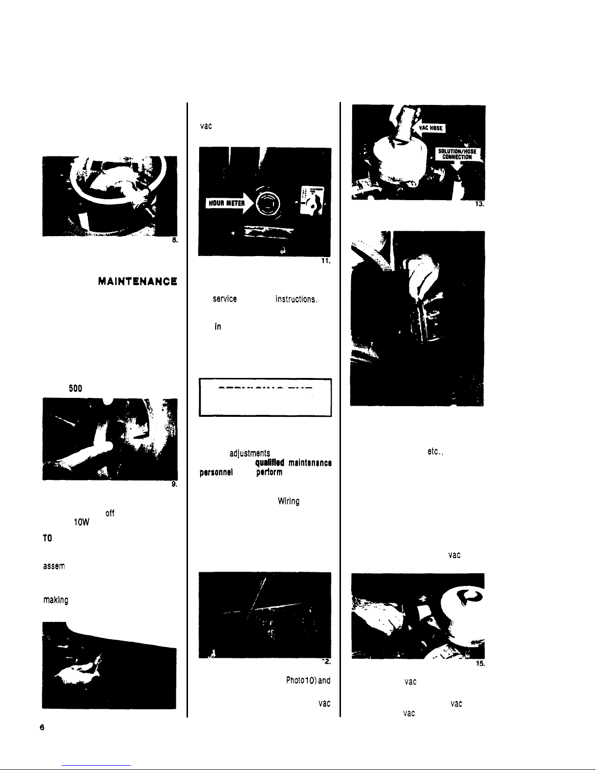
COMMODORE
115V
STORE
COMMODORE
with recovery
shoe in the “up” position. Place
recovery dome upside down in recovery
tank as shown
to
permit drying of
gasket and the inside
of
the tank.
INSPECT
screens in solution and re
covery tank. Remove and rinse with
hot water.
PERIODIC MAINTENANCE
EVERY
TWO
WEEKS:
CLEAN SOLUTION SYSTEM
by diluting
2
gallons of clean water with a quart of
white vinegar (acetic acid) in solution
tank. Run solution through the system
with the machine parked over a floor
draln. This procedure will free the
system of harmful buildups which
could eventually cause it
to
plug.
EVERY
OPERATING HOURS:
OIL FRONT DRIVE WHEEL BEARINGS
by
removing hub cap and snap ring on
axle. Slide wheel
axle
and
apply
6
drops of
oil
to
bearings.
SPECTION
loosen screws holding tank
support bracket
to
frame and
tilt
tank
WARNING:
Remove machine power
cord from electrical source before
to
the machine.
EXPOSE WORKING PARTS
FOR IN-
1
0.
THE HOUR METER
keeps track of
operating hours.
It
is wired into the
so
that all operations
using the vacuum are recorded.
REMOVE VACUUM MOTOR
to
inspect
carbon brushes for wear.
If
worn to
3/8
inch, the brushes should be replaced.
See
USE COMPRESSED AIR
to
blow out
dust
SERVICING THE
COMMODORE
WARNING:
Remove machine power
cord from electrical source before mak
-
ing any adjustments or repairs
to
the
machine.
Only
an
to
CAUTION:
When replacing electrical
parts refer
to
machine Wiring Diagram
for proper connections.
TANK REMOVAL
1.
Empty solution and waste water
tanks
.
I
2.
Loosen screws holding tank support
bracket
to
frame (see Photo10)and
tip tank assembly forward.
3.
Disconnect hoses from tank and vac
motor.
4.
Remove front hinge pins and
set
tank
aside.
14.
TANK REPAIR:
The tanks are made of Polythylene.
Small holes, cracks,
-
paired by using heat. Apply low heat
from torch
to
damaged area
until
material is softened. Use screw driver
blade or other flat metal tool
to
seal
damaged area.
VACUUMMOTOR
REMOVAL
1.
Disconnect hose from vac motor
exhaust.
2.
Disconnect vac motor leads from
3.
Remove 3 screws holding vac motor
terminal block.
and remove
Page 7

COMMODORE
1
15V
4.
To
inspect
motor
brushes, remove
metal band around motor and remove
brush holder assembly. Brushes
should be replaced when worn
to
or
after about
750
operating
hours. After second brush replace
ment, armature commutator should
be checked
for
pitting and concen
-
tricity. Vacuum motors can be re
-
paired but such repairs should be
made
by
a qualified
motor
repair
shop.
SOLUTION
PUMP
REMOVAL
1.
Disconnect solution lines at pump.
2.
Remove
(4)
screws holding pump
to
base.
3.
pump up
to
access solution inlet
line and disconnect from pump head.
Refer
to
Pump Drawing for Replace
-
ment
Pump Parts.
CAUTION:
When replacing fittings
on
pump head
as this could crack inlet and outlet
ports in pump head.
SOLENOID VALVE
REMOVAL
1.
Disconnect solenold valve leads
from terminal block.
2.
Disconnect solution hoses from
solenoid valve.
3.
(2)
screws holding valve
to
chassis.
4.
Clean.
repair, or replace
as
required.
REMOVAL
1.
Remove belt guard.
2.
Lay machine on side and remove
brush pulley guard.
3.
Roll belt
off
motor pulley.
4.
(2)
screws holding
seal
plate.
5.
Remove screw from each end
of
6.
Swing brush assembly out of housing
BRUSH %HAP TIBRUSH
1.
Remove the large snap ring from
brush pulley.
2.
Drive the shaft and bearing out from
OPPOSITE
pulley end.
NOTE:
x
2”
screw into
threaded shaft or use
a
brass drift
to
prevent damage
to
internal threads
in shaft.
brush shaft.
to
remove belt.
NEW
BRUSH BEARINQS
Install bearing
OPPOSITE
pulley end
first.
2.
Install shaft making sure
snap
ring is on shaft.
3.
Install bearing in pulley. Use arbor
press or tap in with a hammer and
socket.
24.
4.
Install the
snap ring on shaft,
and bearing retaining snap ring inside
pulley.
7
Page 8

COMMODORE
1
1.
Remove belt guard.
2.
Roll
belt
off
motor pulley.
3.
Loosen set screws in locking collars
on pivot shaft. Slide out shaft
to
lower brush head assembly.
BRUSH DRIVE
MOTOR
1.
To
access motor mounting bolts,
lower brush head assembly.
2.
Disconnect motor leads from terminal
block.
3.
(4)
motor mounting screws.
4.
Lift out motor and repair or replace
as required.
NOTE:
When reinstalling motor,
make sure pulleys are properly
aligned and belt tension is adjusted
to
prevent slipping.
VACUUM
SHOE
1.
Remove upper link arms.
2.
Remove ball joint linkage.
3.
Disconnect
lift
cable from vac shoe.
4.
Remove tension springs.
5.
Repair or replace as required.
VAC
SHOE
ADJUSTMENT
NOTE:
When replacing vac shoe or bail
With machine on smooth level
the front and rear shoe of vac casting
should be parallel with surface.
1.
If front of shoe is off floor (Fig.
3),
lengthen lower adjusting rods.
2.
If
of shoe is off floor (Fig.
2),
shorten lower adjusting rods.
3.
Retighten lock nuts on adjusting
rods after completing
adjustment.
Shoe Hdght Adjustment
-
shoe, Lever should have
level surface, lower
approximately
1
"
of
additional forward travel
when properly adjusted.
Lengthen or shorten lift
rods
A
as required
(Fig.
4).
TO
ADJUST VAC SHOE
1.
"
tracking.
"
2.
If shoe pulls
to
the
tighten right
hand spring adjusting knob.
3.
It
shoe pulls
to
the
RIGHT
tighten
left hand spring adjusting knob.
27.
AND CLUTCH RLMOVAL
1.
Disconnect motor leads.
2.
Disconnect leads from clutch coil.
3.
Remove chain.
NOTE:
Chain has
master link for easy removal.
4.
Remove
(4)
bolts
holding motor
to
chassis and lift out motor.
5.
brush
cap
and inspect motor
brushes periodically. Brushes should
be replaced when they reach
length or after approximately
750
sealed and permanently lubricated
for the
CLUTCH REMOVAL
AND
Depending on the duty cycle of the
clutch, periodic inspections and clean
-
ing of the clutch
parts
should
be
made.
1.
Remove
bolt from center of gear unit
shaft.
2.
Remove bolt holding clutch stabaliz-
ing arm.
3.
Remove sprocket from shaft. Use
bearing puller as needed.
Page 9

COMMODORE
1
32.
To check clutch coil
1.
Disconnect machine power cord from
2.
Disconnect clutch lead connection.
3.
Set
to
check ohms.
4.
Connect meter leads
to
clutch leads.
If the meter reads below
160
ohms
or above
195
ohms replace coil.
Accumulation
of
and
may bause the clutch
to
lose traction. Remove clutch and
clean
solvent.
outlet.
ASSEMBLY REMOVAL
1.
28).
2.
Lay machine on side.
3.
Remove nuts and bolts holding
flange bearing to frame.
Remove axle assembly from machine
and put on workbench
to
service.
5.
Remove snap ring on each end of
axle
to
remove wheels.
WHEEL AND AXLE
1.
Install flange bearing on axle.
Po
-
sition set screws (in locking collars)
over innermost flats on axle and
tighten screws.
of bearings may be necessary when
to
frame.)
2.
When replacing sprocket on axle
note dimension
-
approximately
3
5/16
from end of axle to face of
sprocket. (Photo
33)
35.
3.
Replacing bearing/clutch bearings
in wheels. Thsss are directional
36.
LEFT WHEEL:
Bearing must be
pressed in from
inboard
wheel with knurbd
end of bearing
sleeve on Inboard
side of wheel.
37.
RIGHT
WHEEL:
Bearing must be
pressed in from
outboard side of
end of bearing
sleeve on
side of wheel.
NOTE:
Both right and left bearing
assem
-
blies must be pressed
in
flush with the
38.
4.
To check assembly: hold axle
-
each wheel should rotate forward
freely and lock on shaft when rota
-
tion is reversed.
COMMODORE
CAUTION: Repalrs should only be at
tempted by qualified personnel since
damage can be done by persons not
experienced
in
working with printed clr-
cuit
boards
and components. TSrting
done
an AC/DC
SWITCHES AND
CIRCUIT
BREAKERS
ohmmeter or continuity tester. The
correct
reading is zero for an
open
and infinity (conti
-
nuity) for a closed
.
BRUSH DRIVE
MOTOR
This motor operates on a
60
hz
circuit
(or
230V
50
machine model).
A
6
amp breaker Is
Installed
in
the drive motor circuit
to
prevent damage
to
the motor in case
an
If the breaker
reset,
check for probable cause:
Incorrect power cord. Use nothing
less than
cable wire size and
no longer than
100
ft
.
2.
Brush height lever set too low. Ad
-
just
to
correct height.
3.
Faulty drive motor. Repair or re
-
place as required.
4.
Brush assembly “locked-up.” Check
for obstruction
-
faulty brush bear
-
ings, etc.
Page 10

COMMODORE
1
1 53118
Motor
65070)
2
67071
3
47075
Kit,
Plate
(for
65067)
-
13
and
10
27225
14 41088
15A 65071
(for
65067)
65072
Pump
(for
650701
SOLID
STATE
CONTROL
BOARD
(DC CIRCUIT)
The
Control Board converts aiter-
nating current (AC)
to
direct current
(DC) for the traverse drive motor and
clutch solenoid.
A
2
amp sio-blow ceramic fuse is
in
-
stalled
in
the motor circuit
to
protect
the circuit
board
and motor
in
the event
an overload condition occurs.
NOTE:
Always use the same type and
size fuse for replacement.
DRIVE
MOTOR
DOES
W
1.
Check continuity (use ohmmeter) of
slow
-
blow fuse.
If fuse blows after replacing, check
for short circuit in system or faulty
motor. If this does not correct prob
-
lem the
PC
Control Board may be
faulty.
NOT
RUN,
CHECK THE
To
test
voltage
at
Control
Board:
Aug power cord into properly grounded
Use AC volt meter
to
check
Input
volt
-
age at terminals AC and
AC
on PC
Board. Voltage should be
(on
11
5
volt
models) and 230V (on
230
volt
models). Use DC
to
check
DC
output
voltage at terminals A+
and
A-.
With the speed control knob
set at MAX
(4)
DC volts should be
95
VDC
10%.
if there is "0" voltage
or the voltage does not remain constant,
this is an indication that the circuit
board is faulty. Replace as required.
TO
TEST
MOTOR:
To test for around or short circuit, first
disconnect machine power cord from
tinuity), the armature is grounded,
To
check for shorted armature, use
ohmmeter
to
measure the resistance
between the motor
is
5
ohms or less, the armature is
short circuited; replace gear motor.
CLUTCH
NOT
WINO:
NOTE:
A 1 amp fast blow fuse is in
-
stalled
in
the clutch actuator circuit
to
protect the PC Control Board in the
event an overload condition occurs.
The fuse is located in
-
line near the
clutch actuator
1.
Check clutch switch (use ohmmeter)
for continuity.
2.
Check in-line 1 amp fuse. If fuse
blows after replacing, the coil is
faulty. Replace as required.
3.
Use a DC volt meter
to
check DC
voltage
to
and
F
-
on Control Board. The DC
voltage
95
VDC
10%.
"0"
or iow voltage or if
the voltage does not remain constant,
the circuit board is faulty. Replace
as required.
PUMP
ASSEMBLY
15
14 12
987
12
15
10
Page 11

COMMODORE
11
CONTROL PANEL ASSEMBLY
Page 12

2
CHASSIS
ASSEMBLY
Page 13

1 76013 Ser.10-32x5/8FHMS
2 41132
3
70119
KCP
4 67010
67012
6
89019
9 27122
10
70126
1/4-28
x
KCP
11
12 03012
13
73045
25
beth
14 4llOll8 Kap,3/16x1.75
17 57032
18 70043
16 22012
OD
0
0
0
A
m
Page 14

COMMODORE
1
15V
14
Page 15

Y
O
.
1 70085
1/4-20
x
9
41129
10 73245 Spring, 2'
Compression
12 09025
13
14
15
27281
Brush
End
17
18
67106
Splash
Guard
19
10-32
x
20
21 09019
Brush
22 67098
,
23 12006
24 70177
1632
x
11
57047
1/4-20 lock
16
26 73241
Pulley
27 35085
Gasket,
I
76 11019
Bell.
CMO
Brush
Drive
I
8
0
Page 16

COMMODORE
1
TANKS
16
Page 17

COMMODORE
1
CONTROL
PANEL
DIAGRAM
115
VOLT
I
‘I
..
CHASSIS
WIRING
1 1
VOLT
n
17
Page 18

COMMODORE
11
CONTROL
WIRING
DIAGRAM
230
VOLT
CHASSIS
WIRING
230
VOLT
I
i
18
Page 19

COMMODORE
COMMODORE
PROBLEM
No
electrical power.
Loss
solution recovery.
No
forward
movement
of
machine.
No
solution flow.
Solution will
not
off.
cleaning.
CAUSE
Dead
electrical circuit.
Faulty
main
power switch
on
machine.
Faulty power cord.
Fuse blown
or
circuit breaker tripped
(on
machine).
Vacuum lever
in
"
off" position.
Faulty
motor
switch.
Worn
motor brushes
or
faulty
motor.
Crack
in
recovery dome.
Obstruction
or
damage in vac shoe linkage
or
Incorrectly installed
or
adjusted vac shoe.
Loose wires at switch
or
connections.
Faulty drive
motor
switch.
Worn
carbon brushes in gear drive motor
or
faulty motor.
Fuse blown
or
circuit breaker tripped
(on
machine).
Faulty speed control potentiometer.
Faulty pump.
Faulty switch.
"
Clogged
"
or
faulty solenoid.
Obstruction in jets.
Faulty switch.
in
solenoid valve
or
faulty valve.
One
or
more jets plugged.
SO
N
Check building circuit breaker
or
fuse box.
Replace switch.
Repair
or
replace power
cord,
or
reset
breaker
after
problem.
Put
lever
in
"on"
position.
Replace switch.
Replace motor brushes
or
motor.
Repair
or
replace.
Remove obstruction, repair or replace
casting.
Adjust
Repair as required.
Replace switch.
Replace fuse
or
reset breaker after
correcting problem.
Replace control.
Replace pump.
Replace switch.
Remove obstruction
or
replace.
Remove and clean jets.
Replace switch.
Remove obstruction
or
replace valve.
Clean jets.
19
 Loading...