

Page 1
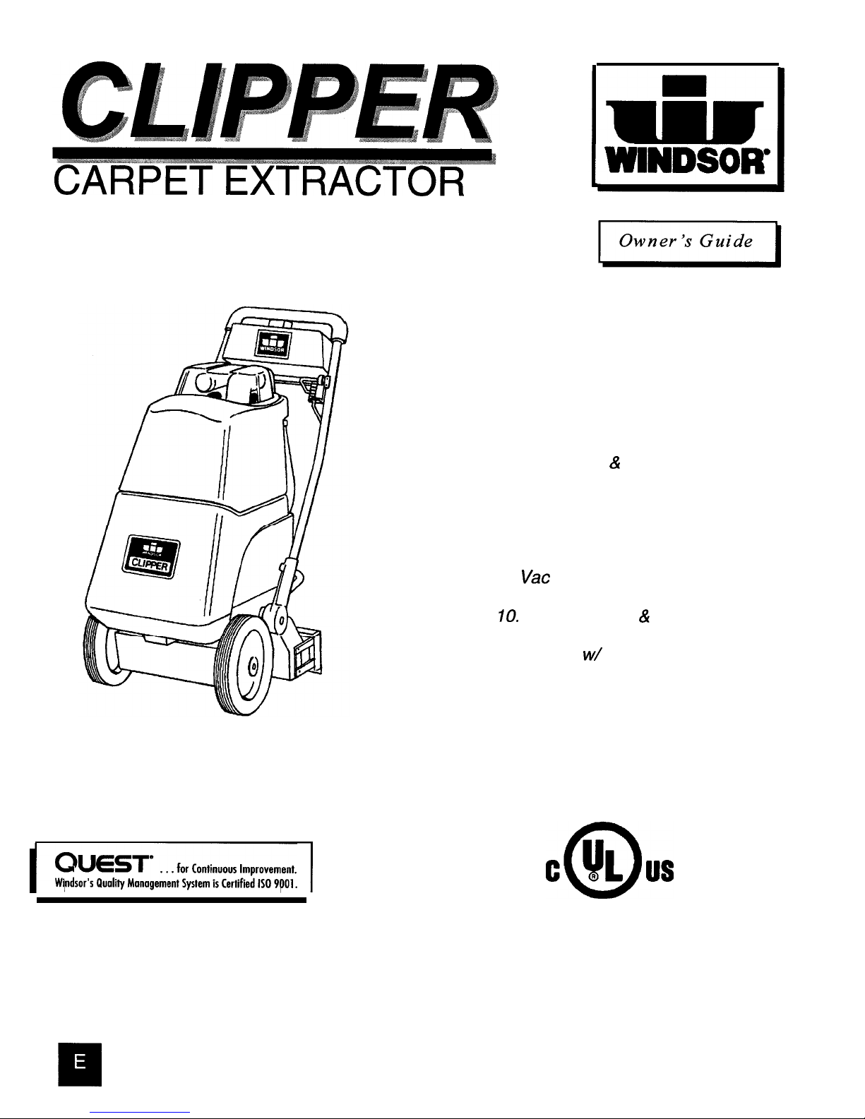
CARPET EXTRACTOR
MODELS: CLP
CLP-J
Contents:
2. Safety Instructions
3. Grounding Instructions
4. Operating the Extractor
5. Operations & Maintenance
6. Service
7. Wiring Diagrams
8.
Vat
and Pump Assembly
IO.
Brush Housing & Drive Assembly
11. Handle w/ Controls Assembly
14. Tank Assembly
.....
Warranty
CLP/CLP-J 98032 2/1/99
Page 2

IMPORTANT SAFETY INSTRUCTIONS
1.
2.
3.
4.
5.
6.
7.
8.
9.
10.
11.
12.
13.
14.
15.
16.
17.
18.
19.
20.
21.
22.
When using an electrical appliance, basic precaution must
always be followed, including the following:
READ ALL INSTRUCTIONS BEFORE USING THIS MACHINE.
This machine is for commercial use.
Do not
operate without filters (dry or wet) in place.
Use
only as described in this manual. Use only manufacturer’s recommended attachments.
Use
indoors only.
Do not
use outdoors and do not expose to rain.
Machine can cause a fire when operating near flammable vapors or materials.
Do not
operate this
machine near flammable fluids, dust or vapors.
Do not
pick up flammable fluids, dust or vapors.
Do not
vacuum anything that is burning or smoking, such as cigarettes, matches, or hot ashes.
Do not
handle the plug or machine with wet hands.
Do not
leave the machine unattended. Unplug machine from outlet when in use and before servicing.
Do not
leave the machine unattended. Unplug machine from outlet when not in use and before servicing.
Do not
unplug machine by pulling on cord. To unplug, grasp the plug,
not
the cord.
Do not
use with damaged cord or plug. Follow all instructions in this manual concerning grounding the
machine.
If the machine is
not working properly,
has been dropped, damaged, left outdoors, or cropped into
water, return it to an Authorized service center.
Do not
pull or carry by cord, use cord as a handle, close a door on cord, or pull cord around
sharp edges or corners.
Do not
pull/run machine over cord.
Keep
cord away from heated surfaces.
Do not
allow to be used as a toy.
Close attention
is necessary when used by or near children.
Do not
operate machine with any openings blocked. Keep openings free of debris that may reduce
airflow.
Keep
hair, loose clothing, fingers, and all parts of the body away from openings and moving
parts.
Use
extra caution when cleaning on stairs,
Do not
use machine as a step.
Connect to a
properly
grounded outlet. See Grounding Instructions.
Maintenance and repairs must be done by qualified personnel.
Rotating fan blades inside the cover. Before opening cover, switch off machine. Wait until the fan/brush
stops completely or dust and debris may be ejected.
SAVE THESE INSTRUCTIONS
98032
7/1/97
Page 3
INSPECTION
Carefully unpack and inspect your extractor for shipping damage. Each unit is operated and thoroughly inspected before shipping, and any damage is the responsibility of the carrier, who
should be notified immediately.
ELECTRICAL
This extractor operates on a standard 15 amp 115 volt AC cir-
cuit. *Voltages below 105 volts or above 125 volts could cause
serious damage to motors. Wiring diagram is mounted inside
handle control panel of machine.
*Special voltage models avail-
able.
WARNING: To avoid electric shock:
1.
Use indoors only.
2. To reduce risk of fire, do not use volatile substances.
3.
Use only cleaners intended for carpet application.
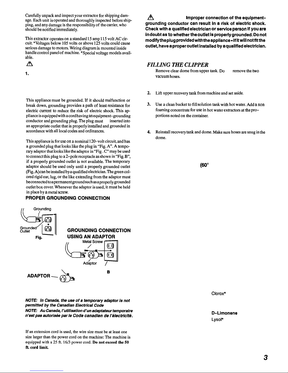
GROUNDING INSTRUCTIONS:
This appliance must be grounded. If it should malfunction or
break down, grounding provides a path of least resistance for
electric current to reduce the risk of electric shock. This appliance is equipped
with a
cord having an equipment-grounding
conductor and grounding plug. The plug must
be
inserted into
an appropriate outlet that is properly installed and grounded in
accordance with all local codes and ordinances.
This appliance is for use on a nominal 120-volt circuit, and has
a grounded plug that looks like the plug in “Fig. A”. A temporary adaptor that looks like the adaptor in “Fig. C” may be used
to
connect
this plug
to a
2-pole receptacle
as shown in
“Fig.
B”,
if a properly grounded outlet is not available. The temporary
adaptor should be used only until a properly grounded outlet
(Fig. A)
can be
installed by
a
qualified electrician.
The green
colored rigid ear, lug, or the like extending from the adaptor must
be connected to a
permanent ground
such as a
properly grounded
outlet box cover. Whenever the adaptor is used, it must be held
in place by a metal screw.
Gro,unding
Pin
Fig.
A
n
Tab For Grounding
Screw
Grounded Outlet Box
Fig.
B
Fig. C
EXTENSION CORDS
90032 7/1/97
A
WARNING:
I
mproper connection of the equipmentgrounding conductor can result in a risk of electric shock.
Check with a qualified electrician or service person if you are
in
doubt as to
whether
the outlet is properly grounded. Do not
modify the plug provided with the appliance - if it will not
fit
outlet, have a proper outlet installed by a qualified electrician.
FILLING THE CLIPPER
1.
Remove clear dome from upper tank. Do
not
remove the two
vacuum hoses.
NOTE: Dome can be set securely between
handle uprights when the handle is in operating position.
2.
Lift upper recovery tank from machine and set aside.
3. Use a clean bucket to fill solution tank with hot water. Add a non
foaming concentrate for use in hot water extractors at the proportions noted on the container.
NOTE: If powdered soap
is
used,
premix
with hot water before
filling solution tank.
4.
Reinstall recovery tank and dome. Make sure hoses are snug in the
dome.
CAUTION:
To avoid possible distortion of polyethylene solution/
recovery tanks, DO NOT USE WATER TEMPERATURE
THAT EXCEEDS 140” F (60’ C).
NOTE: Make sure dome is seated correctly to ensure proper vacuum seal.
CHEMICALS
CAUTION:
Use only the suitable chemicals listed below. Using incompatible chemicals will damage the machine. Damages of this type are not covered under warranty.
Carefully read ingredients on manufacturer’s label before using any product in this machine.
SUITABLE
CHEMICALS
Alkalis
Clorox II Bleach*
Defoaming Agents
Detergents
Hydroxides
Oxygen Bleaches
Soaps
Sta- Puf Fabric Softener*
Vinegar
White Monday Bleach*
* Registered Trademark
INCOMPATIBLE
CHEMICALS
Aldehydes
Aromatic Hydrocarbons
Butyls
Carbon Tetrachloride
CIorox*
Chlorinated Bleaches
Chlorinated Hydrocarbons
D-Llmonene
Lysol*
Methyls (MEK)
Perchlorethylene(perc)
Phenols
Trichlorethylene
3
Page 4
NOTE:
Vacuum the carpet and make sure it is cleared of
surface debris before cleaning with the CLIPPER.
NOTE: Attach strain relief/cord retainer to the power cord.
1.
Make a loop in power cord
approximately 12” from twist
lock receptacle end.
2.
Slide cord loop through slot in
retainer arm. Pull slack cord back
through slot to secure. Attach
retainer to handle.
For larger unobstructed areas, reverse the handle and
use the machine’s brush assisted propelling motion.
q
4.
Adjust brush to proper cleaning position by using
lever located at lower back of the motor housing.
Start at No. 1 “new brush” (black) position. If more
carpet pile agitation is desired, lower brush setting
one position at a time. (Fig. 1)
A
Recovery tank drain hose
:
Vacuum recovery hose
Vacuum hose
D
Solution tank drain hose
E
Auxiliary tool outlet nipple
Solution directional
G
Brush height adjustment lever
5.
Check to be sure solution dlrectional valve Is set
on “Carpet Spray” position. (Fig. 3)
VAC
SWITCH
CONTINUOUS
PUMP
SWITCH
BRUSH
SWITCH
I
BRUSH
RESET
I VAC
4
98032 7/l/97
Page 5
OPERATING THE CLIPPER
(Cont.)
NOTE:
1.
Starting the machine with dry brush resting on the carpet
may trip brush circuit breaker.
2.
The vacuum motor is also protected by a circuit breaker.
The breaker will only trip under conditions of abuse or
faulty vac motor.
Dispense solution by using either the
“Continuous Flow”
switch
for
large, open areas or the
“Intermittent Solution”
button for cleaning in smaller, more confined areas. Walking backwards, move the machine over the area to be cleaned.
The machine’s brush assistance should allow the unit to be
moved
As you work, check to see if there is a foam build up in the
recovery bucket, If there is, turn the machine off and add
the recommended amount of defoaming compound to the
recovery
tank.
Never put defoamer in solution tank!
WARNING:
An overflow of foam into the vacuum intake can
damage the vac motor. Always be aware of the waste water level
in the recovery tank. When is about three-quarters full, turn off
the machine, remove the dome and lift off the recovery tank to
empty. The tank has a convenient carrying handle grip on the
underside.
9.
When the machine runs out of cleaning solution (this can
be easily detected by streaking and incomplete cleaning of
the carpet, or by looking at spray manifold from side of
machine) turn off the machine, remove the dome and recovery bucket, and re-fill the clean solution tank. Replace
the recovery tank and dome. Turn the machine back on and
continue cleaning.
10.
Ventilate area after carpet has been cleaned. Keep children
and pets away and do not walk on carpet until it is throughly dry.
OPERATING THE CLIPPER WITH
ACCESSORY TOOLS
The CLIPPER is easily adapted for use with the following Windsor
accessory tools: DHT-UPII3-SW-SFW-SW/PRO
1.
Turn
solution valve to “Accessory Tool”
position.
2.
Remove recovery hose from dome and insert vacuum hose
for accessory tool in its place.
3.
Attach solution hose from accessory tool to brass solution
nipple on lower back of chassis.
4.
Make sure that solution tank has cleaning solution and that
recovery tank and dome are in place and ready for operation.
5. Switch on CLIPPER’s
Vacuum and Continuous switches
only.
Use accessory tools as with and standard extractor.
WARNING:
Do not switch on brush switch when operating the
machine with accessory tools. Carpet damage may occur.
6.
Make sure that the solution valve is returned to the
“Carpet
Spray”
position before using the machine again for self-
contained carpet cleaning.
I
1
NOTE:
In the following instructions all letter
will be shown in the up-
coming graphical examples in this guide.
MAINTENANCE INSTRUCTIONS FOR CLIPPER
WARNING:
Remove machine power cord from electrical
source before making any adjustments or repairs to the machine.
Only qualified maintenance personnel are to perform repairs.
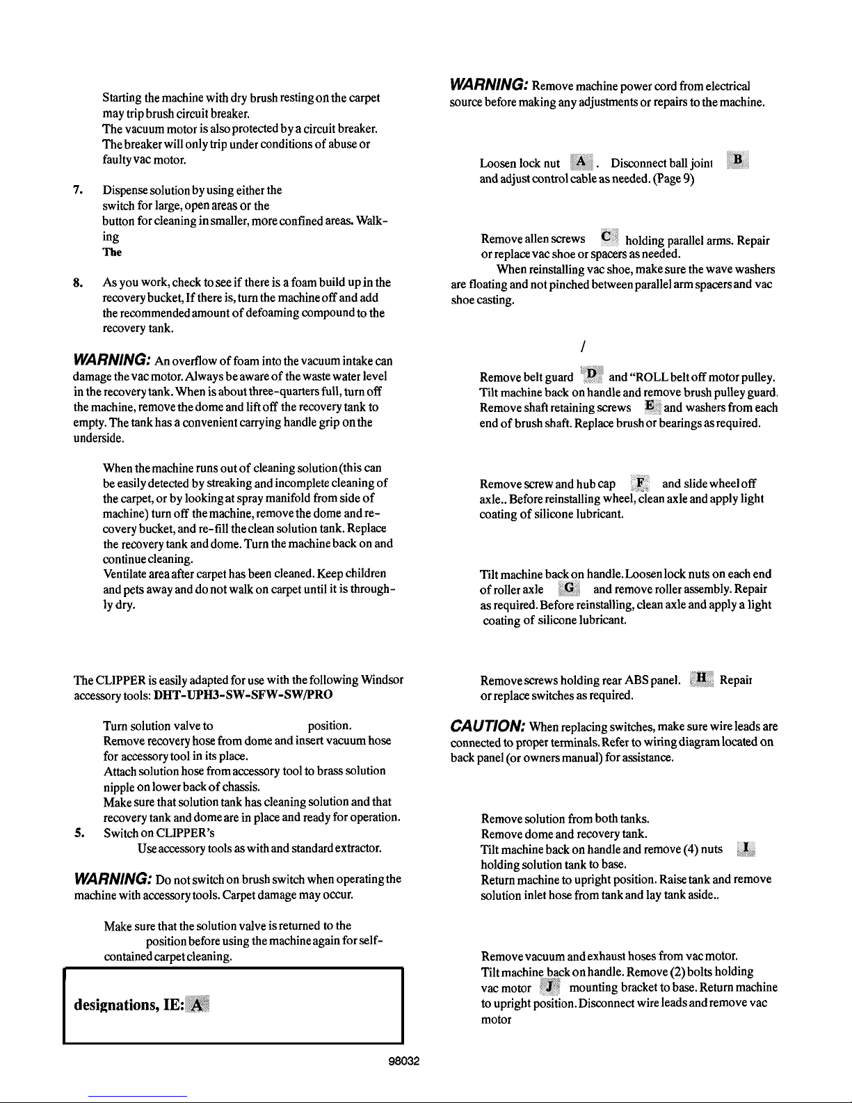
To adjust handle locking lever
1.
and adjust control cable as needed. (Page 9)
VAC SHOE
1.
Remove allen screws
or replace vac shoe or spacers as needed.
NOTE:
When reinstalling vac shoe, make sure the wave washers
are floating and not pinched between parallel arm spacers and vac
shoe casting.
BRUSH ASSEMBLY / BEARING
1.
2.
3.
Remove belt guard
and “ROLL belt off motor pulley.
Tilt machine back on handle and remove brush pulley guard.
Remove shaft retaining screws I$,: and washers from each
end of brush shaft. Replace brush or bearings as required.
TRANSPORT WHEELS
1.
Remove screw and hub cap
and slide wheel off
I . :
axle.. Before reinstalling wheel, clean axle and apply light
coating of silicone lubricant.
SUPPORT ROLLER
1.
Tilt machine back on handle. Loosen lock nuts on each end
of roller axle
and remove roller assembly. Repair
as required. Before reinstalling, clean axle and apply a light
coating of silicone lubricant.
SWITCH CONTROL PANEL
1.
Remove screws holding rear ABS panel.
or replace switches as required.
CAUTION:
When replacing switches, make sure wire leads are
connected to proper terminals. Refer to wiring diagram located on
back panel (or owners manual) for assistance.
TO ACCESS VAC, PUMP AND BRUSH MOTOR
1.
2.
3.
4.
Remove solution from both tanks.
Remove dome and recovery tank.
Tilt machine back on handle and remove (4) nuts
holding solution tank to base.
Return machine to upright position. Raise tank and remove
solution inlet hose from tank and lay tank aside..
VAC MOTOR
1.
Remove vacuum and exhaust hoses from vat motor.
2.
Tilt machine,back on handle. Remove (2) bolts holding
mounting bracket to base. Return machine
to upright position. Disconnect wire leads and remove vac
motor
5
98032
Page 6

VAC MOTOR
(cont.)
3.
To inspect motor brushes, remove brush holder assembly.
Brushes should be replaced when worn to 3/8 inch or after
about 750 operating hours. After second brush replacement,
the armature commutator should be checked for pitting and
concentricity. Vac motors can be repaired but such repairs
should be made by a qualified motor repair shop.
The green ground wire
must attach the motor to
the power cord
for
safe op-
eration. See wiring dia-
(actual size)
PUMP ASSEMBLY
1.
Disconnect pump motor leads. Remove (4) screws holding pump
to chassis
lift out pump. Refer to pump drawing for replacement parts.
CAUTION:
When replacing hosebarbs on pump head- DO
NOT OVERTIGHTEN- as this could crack intake and exhaust
ports in the pump head.
WARNING:
The internal solution hoses are encased in an outer
hose to protect the electrical component parts in the unlikely event
a solution hose should rupture. Replace hoses exactly as originally
supplied.
SOLUTION VALVE
1.
Remove recovery and solution tanks.
2.
Remove auxiliary solution outlet nipple.
3.
Remove solution valve lever..
4.
Remove (2) screws holding valve clamp to chassis.
5.
Lift out valve asm, and disconnect solution hoses. Repair
as required.
VAC EXHAUST MUFFLER
1.
Remove exhaust hose from muffler elbow.
2.
Tilt machine back on handle. Remove exhaust deflector and
hex retaining nut
as required.
MANIFOLD ASSEMBLY
1.
Remove pump from chassis to access solution outlet hose..
2.
Remove hose from hosebarb on manifold.
3.
Tilt machine
back on handle. Remove (2) screws holding
manifold to chassis
Remove manifold and repair as
required.
SPRAY JETS
1.
To prevent clogged jets due to alkaline build-up, the spray
system should be flushed with 1 to 2 gallons of clean hot
water at the end of each day. The machine is equipped with
“Quick Change” jets that can be easily removed for cleaning.
To remove - push jet in and rotate l/4 turn. Wash jets and blow
dry. Do not use pins or wire to remove obstruction as this will
change spray pattern.
BRUSH DRIVE MOTOR
1.
Remove exhaust hose from vac motor.
2.
Disconnect motor lead wires.
3.
Move brush adjustment lever to
lowest
position and tilt machine
back on handle.
4.
5.
Return machine to upright position and lift out motor. Repair
or replace as required.
NOTE:
When reinstalling motor, make sure motor pulley is in line with
brush pulley. Use straight edge for alignment if needed. After assembly
run machine on carpet to check for belt slippage - move rearward to
tighten belt.
DAILY / REGULAR MAINTENANCE.
1.
Empty unused cleaning solution using clear plastic hose located
on lower back of solution tank.
2.
Inspect and clean filter screen in solution tank.
3.
Flush pumping system with 1 or 2 gallons of clean, hot water.
4.
After each use, rinse tank with fresh water. Periodically inspect the
recovery tank and decontaminate if necessary, using a Hospital
Grade Virucide or a l-10 bleach to water solution. Waste water
should be disposed of properly.
Rinse recovery tank with clean water.
5. Check for and remove any lint or debris around brush and vac.
shoe.
6.
Check spray jets and clean solenoid valve if required.
NOTE:
Always store machine with brush in “Store” position.
PERIODIC MAINTENANCE
Twice a month, flush a white vinegar solution (One quart vinegar
to two gallons of water) or anti-browning solution (mixed as
directed) through the extractor. This will prevent build-up of
alkaline residue in the system.
If spray jets become clogged, remove the spray tips, wash them
thoroughly, and blow dry.
NOTE:
Do not use pins, wire, etc. to clean nozzles as this could destroy
spray pattern.
If spray jets drip after the pump is turned off, solenoid valve may
need to be cleaned.
Apply silicone lubricant to solution nipple.
Periodically inspect all hoses, electrical cables, filters and connections on your machine. Frayed or cracked hoses should be
repaired or replaced to eliminate vacuum or solution pressure
loss. Because the electrical cable must be well insulated and cable
connector screws kept tight, If the cable insulation is broken or
’
frayed, repair or replace it immediately. Don’t take chances with
electrical fire or shock.
PROTECT FROM FREEZING
If it becomes necessary to store in temperatures that could drop below
40 F, the pumping system, hoses and valves must be protected from
freezing with a methyl hydrate window washer antifreeze solution. Do
not
use ethylene glycol or cooling system antifreezes.
1.
2.
Add a gallon or two of window washer antifreeze to the supply
tank, turn on pump switch and spray until the antifreeze solution
fills the solution lines.
Drain out the leftover antifreeze from the supply tank. Always
allow the unit to reach room temperatures before filling with
hot water or operating.
Page 7

Page 8

VAC & PUMP ASSEMBLY
8
98032 7/l 8198
Page 9

CL P 98032
7/l 6/98
9
Page 10

BRUSH
HOUSING &
DRIVE ASSEMBLY
10
Page 11

BRUSH HOUSING & DRlvE ASSEMBLY
Parts List
Page 12

HANDLE
CONTROLS ASSEMBLY
12
98032 7/1/97
Page 13

HANDLE
w/ CONTROLS
ASSEMBLY
Parts List
98032
10/21/98
13
Page 14

TANK ASSEMBLY
CL P 98032 1/14/98
Page 15

TANK ASSEMBLY Parts List
Ref Part No. Qty Description
Serial
No.
From To
1
40027 Hosebarb,
318
MPT x 112 90D
2
39360
3
-
4 20072
5
40042
6
04008
7
78156
8
40033
9
40068
10A
50623
1OB
50676
11
57105
12
-
13
-
14
75247
15
-
16
-
17
-
18
73864
19
75145
Hose, Drain
w/sol’n
level
Open
Clamp, 318 Hose
Hosebarb, 114 MPT x
112 90D
Adapter,
114
MPT x
l/2 90D
Tee, 114 FPT
Hosebarb, 114 MPT x 318 90D
Hosebarb,
318
NPT x
l/2
Tee
Label, Chassis Wiring
115V
Label, Chassis Wiring 230V
Nut,
l/4-20
w/Star Washer
Open
Open
Tank, CLP Solution
Open
Open
Open
Strainer, 3/8 NPT x 60 Mesh
Tank, Recovery
442941
442941
442941
20
21
22
23
24
25
26
27
28
29
30
31
32
33
34
35
36
37
38
39
40
41
42
43
44
45
46
47
-
-
20002
39353
14520
87017
70052
66152
99807
34017
40019
70011
87013
14630
35060
34140
28034
39358
27354
14042
39359
27079
04071
39367
40023
02130
50776
50775
OPEN
OPEN
Clamp, 2” Nylon Ratchet
Hose, 1.5 x 12” Drain
Clip, Drain Hose
Washer, #8 Flat
Scr, 8-32 x
318
PHMS
Plug, Drain Hose
Cord, 1/8 x 12”
Ferrule
Hosebarb, 1.5 MCHD
Scr,
l/4-20
x 5/8 HHMS
Washer,
l/4
Flat
Bracket, Hose Retainer
Gasket, Dome
Filter, Vac Intake 10 Mesh
Dome
Hose Asm, 1.5 Vac x 34” w/cuff
Cuff, Blue SIC Vac Hose
Bushing, 1.63 Snap
Hose Asm, 1.5 Vac x
26”wlcuff s
Cuff, 1.5 White Hose
Adapter, Faucet
Hose, 3/8 Nylobraid x 60”
Hosebarb, 1/2 MPT x
3/8
Fill Hose Asm
(#4,42,43,44)
Label, For Safety
Label, Explosion Warning
Notes:
442941
CL P 98032
l1/14/98
15
Page 16

LIMITED WARRANTY
Windsor Industries, Inc. warrants new machines against defects in material and workmanship
under normal use and service to the original purchaser. The warranty period is subject to the
conditions stated below.
3 YEARS FOR PARTS AND I YEAR FOR SERVICE LABOR
Exceptions: Rotationally molded polyethylene tanks carry a 6 year parts and 1 year service
motors, and belts, and a 1 year service labor warranty. SENSOR” models carry a 2 year
warranty on vacuum motors and belts, and a 1 year service labor warranty. Extractor brush
motors, pump motors, pc boards and electronics,
vat
motors (other than VERSAMATIC” and
SENSOR’), pumps, and
FLEXSOLTM
diaphragms, all
RADIUSTM,
all
AXCESSTM
and
TITANTM1
carry a 1 year parts and service labor warranty. Propane equipment has a I year
parts and service warranty. The
Onan@
engines have a 3 year manufacturers’ warranty. The
Honda@ engines have a 2 year manufacturers’ warranty. The engine warranty is administered
through the engine manufacturer and must be repaired at an authorized service center.
Normal wear items including, but not limited to, belts, brushes, capacitors, carbon brushes,
casters, clutches, cords, filters, finishes, gaskets, hoses, light bulbs, rectifiers, switches, squee-
gees, bearings, pulleys, relays, actuating cables, tires and wheels will be warranted for
manufacturing defects for 90 days from the purchase date.
The warranty commences on the purchase date by the original end user from an authorized
Windsor Agent, subject to proof of purchase. The Machine Registration Card must be
completed and returned immediately at the time of purchase. If proof of purchase cannot be
identified, the warranty start date is 90 days after date of sale to an authorized Windsor
distributor. Parts replaced or repaired under warranty are guaranteed for the remainder of the
original warranty period.
90
DAY WARRANTY EXTENSION AVAILABLE
Upon receipt of the Machine Registration Card, Windsor will extend the warranty period an
additional 90 days from the purchase date. Does not include items warranted 90 days for
manufacturing defects.
STATED WARRANTIES ARE IN LIEU OF ALL OTHER WARRANTIES,
EXPRESSED OR IMPLIED.
Any statutory implied warranties, including any warranty of merchantability or fitness for a
particular purpose, are expressly limited to the duration of this written warranty. Windsor will not
be liable for any other damages, including but not limited to indirect or special consequential
damages arising out of or in connection with the furnishing; performance, use or inability to use
the machine. This remedy shall be the exclusive remedy of the buyer.
This warranty shall not apply to: 1
.damage
in transit;
2.misuse
or abuse(including the use of
incompatible or corrosive chemicals or overloading of capacity); 3. failure due to lack of proper
maintenance and care (including cleaning);
4.any
design alterations performed by an
organization not authorized or specified by Windsor;
5batteries
and chargers. 6. high pressure
washing.
7.electrical
components exposed to moisture.
If difficulty develops during the warranty period, contact the authorized Windsor Agent from
whom the product was purchased. Windsor, Inc. may elect to require the return of components
to validate a claim. Any defective part to be returned must be shipped freight pre-paid to an
authorized Windsor Distributor/Service Center or to the Windsor factory.
USE OF PARTS NOT APPROVED BY WINDSOR, INC.
WILL VOID ALL WARRANTIES.
This warranty is valid only for all products sold after July 1, 1995. A product sold before that
date shall be covered by the limited Warranty in effect at the date of sale to the original
purchaser.
WINDSOR INDUSTRIES, INC., 1351 W. Stanford Ave., Englewood, CO 80110 USA
WINDSOR’
Phone:
303-762-1800
Fax:
303-762-0817
Internet: www.windsorind.com
 Loading...