

Page 1

Saber Cutter - Euro - 24V - Standard
Walk Behind Scrubber
Operating Instructions (ENG)
MODELS:
SCE264
10052270
From Serial Number (Ref No1*)
*See Serial Number Page
in Spare Parts List
or call manufacturer.
86400370-A 04/15/15
Page 2

Warranty Registration
Thank you for purchasing a Kärcher North America product. Warranty registration is quick
and easy. Your registration will allow us to serve you better over the lifetime of the product.
To register your product go to :
http://warranty.karcherna.com/
For customer assistance:
1-800-444-7654
Machine Data Label
Overview
The Saber Cutter is a battery powered, self-propelled, hard floor scrubber intended for commercial use. The
appliance applies a cleaning solution onto a hard floor, scru bs the floor with brushes or pads, and then vacuums the
soiled water back into the recovery tank.
2 86400370 Manual Operators - EURO 24V Standard
Page 3

Machine Data Label. . . . . . . . . . . . . . . . . . . . . . . . . .2
Overview. . . . . . . . . . . . . . . . . . . . . . . . . . . . . . . . . .2
Table of Contents . . . . . . . . . . . . . . . . . . . . . . . . . . .3
How To Use This Manual . . . . . . . . . . . . . . . . . . . . .4
Safety
Important Safety Instructions . . . . . . . . . . . . . . . . . .5
Hazard Intensity Level . . . . . . . . . . . . . . . . . . . . . . .7
Safety Labels . . . . . . . . . . . . . . . . . . . . . . . . . . . . . .9
Operations
Technical Specifications . . . . . . . . . . . . . . . . . . . . .10
How The Machine Works . . . . . . . . . . . . . . . . . . . .12
Controls. . . . . . . . . . . . . . . . . . . . . . . . . . . . . . . . . .15
Machine Operation . . . . . . . . . . . . . . . . . . . . . . . . .18
Double Scrub . . . . . . . . . . . . . . . . . . . . . . . . . . . . .20
Emptying And Cleaning Tanks . . . . . . . . . . . . . . . .20
Maintenance
Service Schedule . . . . . . . . . . . . . . . . . . . . . . . . . .21
Batteries . . . . . . . . . . . . . . . . . . . . . . . . . . . . . . . . .22
Checking Battery Specific Gravity. . . . . . . . . . . . . .24
To Charge The Batteries. . . . . . . . . . . . . . . . . . . . .24
Changing Batteries . . . . . . . . . . . . . . . . . . . . . . . . .25
Adjusting Squeegee . . . . . . . . . . . . . . . . . . . . . . . .26
To Remove Squeegee Assembly . . . . . . . . . . . . . .26
To Replace Or Rotate Rear Squeegee Blades. . . .26
To Replace Or Rotate Front Squeegee Blade . . . .26
To Adjust Squeegee Pitch . . . . . . . . . . . . . . . . . . .27
To Adjust Amount Of Rear Squeegee Deflection . .27
Changing Brush Motors . . . . . . . . . . . . . . . . . . . . .29
Brush Motor Carbon Brush Replacement. . . . . . . .29
Greasing Axle . . . . . . . . . . . . . . . . . . . . . . . . . . . . .32
Troubleshooting . . . . . . . . . . . . . . . . . . . . . . . . . . .33
Suggested Spare Parts. . . . . . . . . . . . . . . . . . . . . .35
Table of Contents
86400370 Manual Operators - EURO 24V Standard
3
Page 4

How To Use This Manual
Model:
Date of Purchase:
Serial Number:
Dealer:
Address:
Phone Number:
Sales Representative:
This manual contains the following sections:
• How to Use This Manual
•Safety
• Operations
• Maintenance
• Suggested Spare Parts
The HOW TO USE THIS MANUAL section will tell you
how to find important information for ordering correct
repair parts.
Parts may be ordered from authorized dealers. When
placing an order for parts, the machine model and
machine serial number are important. Refer to the
MACHINE DATA box which is filled out during the
installation of your machine. The MACHINE DATA box
is located on the inside of the front cover of this manual.
The SAFETY section contains important information
regarding hazardous or unsafe practices of the
machine. Levels of hazards are identified that could
result in product damage, personal injury, or severe
injury resulting in death.
The OPERAT IONS section is to familiarize the operator
with the operation and function of the machine.
The MAINTENANCE section contains preventive maintenance to keep the machine and its components in
good working condition. They are listed in this general
order:
• Batteries
• Scrub Brushes
• Adjusting Squeegee
•Scrub Deck Skirts
• Squeegee Blade
• Service Schedule
NOTE: If a service or option kit is installed on your
machine, be sure to keep the KIT INSTRUCTIONS
which came with the kit. It contains replacement parts
numbers needed for ordering future parts.
The model and serial number of your machine is
located on the back of the machine.
NOTE: The manual part number is located on the
lower right corner of the front cover.
4
86400370 Manual Operators - EURO 24V Standard
Page 5

Safety
Important Safety Instructions
When using this machine, basic precaution
must always be followed, including the following:
READ ALL INSTRUCTIONS BEFORE USING THIS MACHINE.
T o reduce the risk of fire, electric shock, or injury:
Use only indoors. Do not use outdoors or expose to rain.
Use only as described in this manual. Use only manufacturer’s recommended components and attachments.
If the machine is not working properly , has bee n dropped, damaged, lef t out doors, or dr opped into water, return it
to an authorized service center.
Do not operate the machine with any openings blocked. Keep openings free of debris that may reduce airflow.
This machine is not suitable for picking up hazardous dust.
Machine can cause a fire when operating near flammable vapors or materials. Do not operate this machine near
flammable fluids, dust or vapors.
This machine is suitable f or commercial use, for example in hotels, s chools, hospita ls, factories, shop s and
offices for more than normal housekeeping purposes.
Maintenance and repairs must be done by qualified personnel.
If foam or liquid comes out of machine, switch off immediately.
Disconnect battery before cleaning or servicing.
Before the machine is discarded, the batteries must be removed and properly disposed of.
Make sure all warning and caution labels are legible and properly attached to the machine.
During operation, attention shall be paid to other persons, especially children.
Before use all covers and doors shall be put in the positions specified in the instructions.
When leaving unattended, secure against unintentional movement.
The machine shall only be operated by instructed and authorized persons.
When leaving unattended, switch off or lock the main power switch to prevent unauthorized use.
Only chemicals recommended by the manufacturer shall be used.
This appliance has been designed for use with the brushes specified by the manufacturer. The fitting of other
brushes may affect its safety.
Do not use on surfaces having a gradient exceeding 2% unless the optional parking brake is installed on the
machine.
READ AND SAVE THESE INSTRUCTIONS
86400370 Manual Operators - EURO 24V Standard
5
Page 6

Safety
MESURES DE SÉCURITÉ IMPORTANTES
Lors de l’utilisation d’un appareil à batteries, il est nécessaire de respecter
systématiquement des mesures de sécurité de base, comme suit :
PRENEZ NOTE DE TOUTES CES MESURES AVANT D’UTILISER CETTE MACHINE.
Pour réduire les risques d’incendie, de chocs électriques, ou de
blessures :
N’utiliser cette machine qu’en intérieur. Ne jamais l’utiliser à l’extérieur ou dans la pluie.
N’utiliser cette machine que comme décrit dans le présent manuel. N’utiliser que les composants et les accesso ires
conseillés par le fabricant.
Lorsque la machine ne fonctionnant pas correctement, a fait l’objet d’une chute ou d’une détérioration, a été laissée à
l’extérieur, est tombée dans l’eau, la retourner au centre de service agréé.
Ne pas opérer la machine lorsque les conduits de ventilation sont bloquées. Débarrasser les débris des conduits, ca r ils
peuvent réduire l’écoulement d’air.
Cette machine n’est pas adaptée au ramassage de poussières dangereuses
Cette machine peut provoquer un incendie lorsqu’elle est utilisée près de vapeurs ou de matériaux inflammables. Ne
pas l’utiliser près de liquides, de poussières ou de vapeurs inflammables.
Cette machine est destinée à un usage commercial. Elle es t recommandée davantage pour les do maines hôtelier,
scolaire, hospitalier, industriel ou pour les bureaux, les chaînes de maga sin, que pour un usage domestique
normal.
L’entretien et les réparations de la machine doivent être effectuées p ar un personnel qualifié.
Si de la mousse ou du liquide sort de la machine, la mettre hors tension immédiatement.
Déconnecter les batteries avant de nettoyer la machine ou de la soumettre à un entretien.
Avant de se débarrasser de la machine, il est nécessaire de retirer les batteries et de les jeter correctement.
S’assurer que toutes les plaques d’avertissement ou de précaution sont lisibles et fixées correctement sur la machine.
Durant la manoeuvre de la machine, prendre garde aux personnes environnantes et notamment aux enfants.
Avant l’utilisation de la machine, veiller à positionner tous les couvercles et portes comme indiqué dans les instructions.
Lorsque la machine est laissée sans surveillance, s’assurer qu’elle ne se déplace pas de manière accidentelle.
Cette machine ne doit être manoeuvrée que par un personnel expérimenté et qualifié.
Lorsque la machine est laissée sans surveillance, la mettre hors tension ou verrouiller l’interrupteur principal afin
d’empêcher un emploi non autorisé.
Seuls les produits chimiques recommandés par le fabricant doivent être utilisés.
Cette machine a été conçue pour être utilisée avec des brosses spécifiées par le fabricant.
L’utilisation d’autres brosses peut affecter sa sûreté.
N'employez pas sur des surfaces ayant un gradient de plus de 2%.
CONSERVER CES INSTRUCTIONS
6
86400370 Manual Operators - EURO 24V Standard
Page 7

Safety
The following symbols are used throughout this guide as indicated in their descriptions:
Hazard Intensity Level
There are three levels of hazard intensity identified by signal words -WARNING and CAUTION and FOR SAFETY.
The level of hazard intensity is determined by the following definitions:
WARNING - Hazards or unsafe practices which COULD result in severe personal injury or death.
CAUTION - Hazards or unsafe practices which could result in min or personal in jury or pr oduct or pr operty damag e.
FOR SAFETY: To Identify actions which must be followed for safe operation of equipment.
Report machine damage or faulty operation immediately. Do not use the machine if it is not in proper operating
condition. Following is information that signals some potentially dangerous conditions to the operator or the
equipment. Read this information carefully. Know when these conditions can exist. Locate all safety devices on
the machine. Please take the necessary steps to train the mac hin e op e ratin g pe rsonnel.
FOR SAFETY:
DO NOT OPERATE MACHINE:
Unless Trained and Authorized.
Unless Operation Guide is Read and understood.
In Flammable or Explosive areas.
In areas with possible falling objects.
WHEN SERVICING MACHINE:
Avoid moving parts. Do not wear loose clot hing; jackets, shirt s, or sleeves when working on the machine.
Use Karcher approved replacement parts.
Batteries emit hydrogen gas. Explosion or fire can result. Keep sparks and open flame away. Keep top
cover in raised position when charging. Keep sparks and flames away from the bat teries. Do not smoke
around batteries.
Disconnect batteries before working on machine. Only qualified personnel should work inside machine.
Always wear eye protection and protective clothing when working on or ne ar batte ries. Avoid sk in co ntact
with the acid contained in the batteries.
Never allow metal to lie across battery tops.
86400370 Manual Operators - EURO 24V Standard
7
Page 8

Safety
Les symboles ci-dessous sont utilisés à travers ce manuel comme illustré dans leurs descriptions :
DEGRÉS DE RISQUES EN CAS DE DANGER
Il existe trois degrés de risques identifiés par les termes signalétiques –AVERTISSEMENT et ATTENTION et
POUR VOTRE SÉCURITÉ. Le degré de risque est défini de la manière suivante:
AVERTISSEMENT - Dangers ou méthodes dangereuses qui POURRAIENT provoquer de graves blessures ou
entraîner la mort.
ATTENTION - Dang ers ou méthode s danger euses qui po urraient pr ovoquer des blessu res lé gères ou une détérioration du produit ou des biens immobiliers.
POUR VOTRE SÉCURITÉ: ce signe permet d’identifier les mesures de précaution à prendre pour assurer
un bon fonctionnement du matériel.
Rendre compte immédiatement d’une défaillance ou d’une détérioration de la machine. Ne pas utiliser la machine
si celle-ci ne fonctionne pas correctement. Lire soigneusement les informations ci-dessous signalant certains
dangers potentiels pour l’opérateur de la machine. L’opérateur doit être absolument au courant de ces dangers
potentiels. Localiser tous les dispositifs de sécurité sur la machine. Il est conseillé de prendre les mesures nécessaires pour former le personnel opérateur.
POUR VOTRE SÉCURITÉ:
NE PAS MANOEUVRER LA MACHINE:
Lorsqu’on n’est pas expérimenté ou qualifié.
Lorsque le guide d’utilisation n’est pas été lu ou compris.
Dans des zones inflammables ou explosives.
Dans des zones où des objets peuvent tomber.
LORS DE L’ENTRETIEN DE LA MACHINE:
Éviter les parties amovibles. Ne pas porter de vêtements amples, tels que des vestes, des chemises ou des
vêtements avec manches lors de l’utilisation de la machine. Utiliser les pièces détachées Karcher homologuées.
Les batteries émettent le gaz d'hydrogène. L'explosion ou le feu peut ré sulter. Étincelles de subsistance et flamme
nue loin. Compartiment de batterie de subsistance ouvert en chargeant. Étincelles et flammes de subsistance loin
des batteries. Ne fumez pas autour des batteries.
Déconnecter les batteries avant de travailler sur la machine. La machine ne doit être confiée qu’à un personnel
qualifié. Porter systématiquement des lunettes et des vêtements de protection lors d’une intervention sur les
batteries ou aux alentours. Éviter tout contact de la peau avec l’acide contenu dans les batteries.
Ne jamais placer d’objets métalliques sur le dessus des batteries.
8
86400370 Manual Operators - EURO 24V Standard
Page 9

Safety
BATTERY CAUTION
86252520
SAFETY DECAL
86252530
CIRCUIT BREAKER DECAL
86400230
2% GRADE WARNING
Safety Labels
NOTE: These drawings indicate the location of safety labels on the machine. If at any time the labels become
illegible, promptly replace them.
EMPLACEMENT DE L'ÉTIQUETTE DE SÉCURITÉ
REMARQUE : Ces dessins indiquent l'emplacement des étiquettes de sécurité sur la machine. Si, à tout moment,
les étiquettes deviennent illisibles, contactez votre représentant autorisé pour un remplacement rapide.
86400370 Manual Operators - EURO 24V Standard
9
Page 10

Operations
Technical Specifications
ITEM DIMENSION/CAPACITY
Nominal power 1450 W
Rated Voltage 24VDC
Rated Amperage 60 Amps
Batteries 4 X 6 Volt 250-305-335 AH @ 20 hr
rate
Scrub Brush Motors 2 X .75 hp (0.56 kW)
Vacuum Motor .75 hp (0.56 Kw)
Propelling Motor .3 hp (0.22 Kw)
Mass (GVW) 915 lbs. (415 kg) with 335 AH
Weight empty without batteries 346 lbs. (157 kg)
Solution Control Gravity feed, fully variable with
automatic shut-off in neutral
Solution tank capacity 23 gal. (87 l)
Recovery tank capacity 25 gal. (95 l)
Scrub brush diameter for 26 in. (66 cm) scrub head 13 in (33.0 cm)
Scrub brush pressure Mechanical 80 lbs. (356N) Floating 130
lbs. (578N) restricted
Scrub brush speed 200 rpm
Tires 2 x 10 in (25.4 cm) non-marking foam-
filled
Casters 2 X 4 in (10.2 cm) polyurethane solid
non-marking
Foundation Pressure
Maximum Speed 3.2 Miles/hour (5.2 km/hour)
Frame Construction Steel plate with epoxy powdercoat finish.
Brakes Tire lock parking brake
Minimum aisle u-turn width with 26 in. (66 cm) scrub head 69 in. (175 cm)
Maximum rated climb and descent angle with empty tanks and
without optional parking brake
Maximum rated climb and descent angle with full tanks and without
optional parking brake
21 lbs./in
2%
2%
2
(140 kPa)
SPECIAL NOTES:
The sound pressure level at the operator’s ear was measured to be 72 dBA. This was a nearfield, broad-band
measurement taken in a typical industrial environment on a tile floor. This a ppliance contains no p ossible source of
impact noise. The instantaneous sound pressure level is below 63 Pa.
The weighted root mean square acceleration at the operator’s arms was me asured to be b elow 2 .5m/s2 . This was
a tri-axial, third-octave-band measurement made during normal operation on a composite tile floor. The measure-
ment and related calculations were made in accordance with ANSI S3.34-1986.
10
86400370 Manual Operators - EURO 24V Standard
Page 11

ITEM MEASURE
Length
Width
Height
Height 45 in. (114 cm)
Length with 26 in. (66 cm) scrub head 64 in. (163 cm)
Width without squeegee and scrub head 24 in. (61 cm)
Width of squeegee for 26 in. (66 cm) scrub head 35 in. (89 cm)
Width of scrub path for 26 in. (66 cm) scrub head 26 in. (66 cm)
Operations
This appliance is not intended for use by persons (including children) with reduced physical, sensory or
mental capabilities, or lack of experience and knowledge, unless they have been given supervision or
instruction concerning use of the appliance by a person responsible for their safety. Children should be
supervised to ensure that they do not play with the appliance.
Cet appareil n'est pas prévu à l'usage des personnes (enfants y compris) avec des possibilités physiques,
sensorielles ou mentales réduites, ou le manque d'expérience et de connaissance, à moins qu'ils aient été
donnés la surveillance ou l'instruction au sujet de l'utilisation de l'appareil par une personne chargé e de
leur sûreté. Des enfants devraient être dirigés pour s'assurer qu'ils ne jouent pas avec l'ap pareil.
86400370 Manual Operators - EURO 24V Standard
11
Page 12

Operations
How The Machine Works
The Saber Cutter is a battery powered, self-propelled,
hard floor scrubber intended for commercial use. The
appliance applies a cleaning solution onto a hard floor,
scrubs the floor with brushes, and then vacuums the
soiled water back into the recovery tank.
The machine's primary systems are the solution
system, scrub system, recovery system, and
directional control system.
The function of the solution system is to store cleaning
solution and deliver it to the scrub system. The solution
system consists of the solution tank, strainer, valve and
controls. The solution tank stores cleaning solution
(water and detergent) until it is delivered to the scrub
system. The strainer protects the valve from debris.
The valve is a solenoid type valve, which controls the
delivery of cleaning solution to the scrub system. The
valve automatically prevents solution flow unless the
scrub brushes are turned on and the machine is being
propelled. The solution control knob controls the
amount of cleaning solution delivered to the scrub
system by controlling the amount of time the valve is
open.
The function of the scrub system is to scrub the floor.
The scrub system consists of two rotary type disk scrub
brushes, motors, scrub deck skirt, lift mechanism and
controls The brushes scrub the floor and the motors
drive the brushes. The brush drive hubs allow the scrub
brushes to follow irregularities and changes in the floor
without loosing contact with floor. The scrub deck skirt
controls the cleaning solution on the floor so that the
squeegee can pick it up. The brush lever is used to
raise and lower the deck. For heavy scrub pressure
lock the lever into the lower notch. Pushing the lever
forward allows you to push down. Pull Back on the
lever to allow it to swing down and out of the way.
The function of the recovery system is to vacuum the
soiled water back into the recovery tank. The recovery
system consists of the squeegee, vacuum motor, float
ball filter, recovery tank and controls. The squeegee
wipes the dirty solution off the floor as the machine
moves forward. The vacuum motor provides suction to
draw the dirty solution off the floor and into the
recovery tank. The recovery tank stores th e dir ty
solution. The float ball filter protects the vacuum fan
from debris and shuts off air going to the recovery tank
when tank is full.
When flow of air is shut off the vacuum motor will
continue to run. At this time the recovery tank must be
drained.
The function of the directional control system is to
control the direction and speed of the machine. The
directional control system consists of the propel control
buttons, reverse button, speed control knob/potentiometer, controller and transaxle. The propel control
buttons actuates switches, which signal forward
pressing the reverse button in addition to one of the
propel control buttons the machine will move in
reverse. The speed control knob actuates a potentiometer, which signals speed. The controller interprets the
forward/reverse signals from the switches and the
speed signal from the potentiometer to command the
transaxle to propel the machine in the direction, and at
the speed, desired.
12
86400370 Manual Operators - EURO 24V Standard
Page 13

Operations
11
9
8
10
4
15
1
14
3
6
13
5
2
7
12
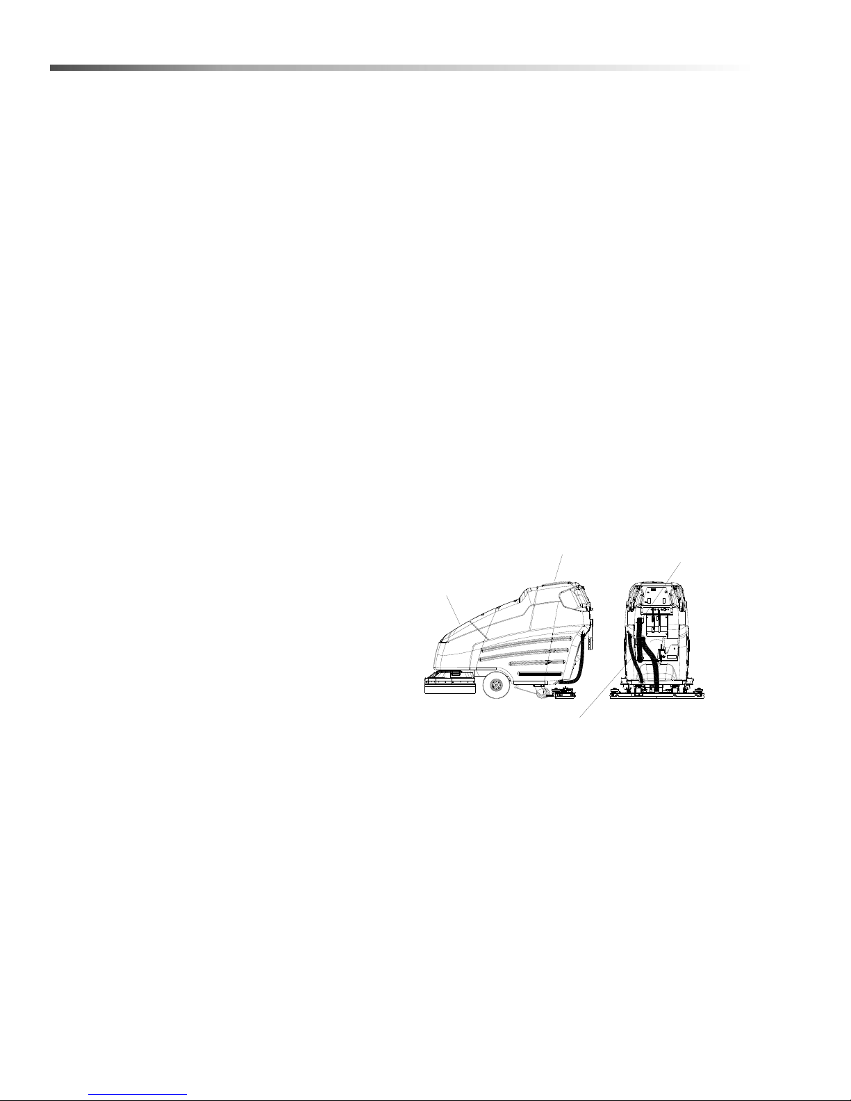
1. Control Panel
2. Front Cover
3. Recovery Tank
4. Recovery Tank Drain Hose
5. Scrub Head Shrouds
6. Solution Tank
7. Solution Tank Cover
8. Solution Tank Drain Hose
9. Solution Strainer
10. Squeegee
11. Aqua-Mizer™
12. Top Cover
13. Vacuum Motor
14. Recovery Tank Dome
15. Accessory Pump Port (Optional)
86400370 Manual Operators - EURO 24V Standard
13
Page 14

Operations
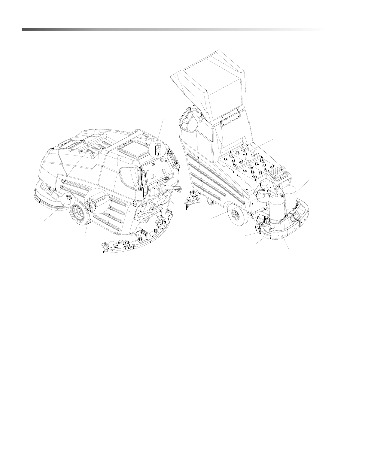
15
5
9
2
3
6
8
14
1
4
10
7
13
11
12
14
86400370 Manual Operators - EURO 24V Standard
Page 15

Controls
Operations
1. Key Switch
2. Battery Charge Level Indicator
3. Speed Control Knob
4. Propel Control Lever
5. Reverse Button
6. Brush Switch
7. Brush Lift Lever
8. Solution Control Knob
1. Key Switch
Controls the power for machine functions.
To turn machine on, rotate key clockwise.
To turn machine off, rotate key counterclockwise.
FOR SAFETY: FOR SAFETY: Always remove the
key when machine is unattended or during
service to prevent unauthorized movement.
9. Vacuum Switch
10. Squeegee Lift Lever
11. Squeegee Pitch Adjustment Knob
12. Squeegee Deflection Adjustment Knobs
13. Parking Brake
14. Hour Meter
15. Emergency Shut-off Switch
4. Propel Control Levers
Controls the machine direction, and scrub brushes
and solution flow.
To propel machine forward, squeeze either propel
lever.
The scrub brushes will not rotate and the solution
will not flow to scrub deck with the propel levers in
neutral.
2. Battery Charge Level Indicator
Indicates the charge level of the batteries.
The meter display is divided into 10 vertical bars.
Bar illuminated on the far right indicate full charge.
Bars flashing near the left side indicate the
batteries should be recharged. Further operation
of the machine could damage the machine or the
batteries.
When the machine is left overnight with less than a
full charge, the display may initially indicate a full
charge. It will also indicate a full charge if the
batteries are disconnected, then rec on nected.
After a few minutes of operation the meter will give
the correct charge level.
3. Speed Control Knob
Controls the speed of the machine.
To increase speed, rotate knob clockwise.
To decrease speed, rotate knob counterclockwise.
5. Reverse Button
Controls the reverse function.
To propel machine backward, push the reverse
button while squeezing either propel lever.
6. Brush Switch
Controls the scrub brush motors.
To turn scrub brushes on, press the bottom of the
switch. The brushes will not rotate with the propel
control levers in neutral.
To turn scrub brushes off, press the top of the
switch.
86400370 Manual Operators - EURO 24V Standard
15
Page 16

Operations
Controls - Continued
7. Brush Pressure Lever
Adjusts the amount of brush pressure to the floor
by raising or lowering the scrub deck.
To apply brush pressure, lower brush pressure
lever to floating position.
To apply additional pressure, place lever in
restricted position. Lock the lever into the lower
notch. Push the lever forward to move in a
downward motion. Pull back on lever and release
for floating position.
To decrease brush pressure, raise lever to up
position.
8. Solution Control Knob
Controls solution flow to scrub deck.
To increase flow, rotate knob clockwise.
To decrease flow, rotate knob counterclockwise.
1 1.Squeegee Pitch Adjustment Knob
Adjusts the deflection at the ends of the squeegee.
To increase squeegee blade deflection at the ends,
turn knob counterclockwise.
To decrease squeegee blade deflection at the
ends, turn knob clockwise.
12.Squeegee Deflection Adjustment
Knobs
Adjusts the deflection along the e ntire length of the
squeegee.
To increase squeegee blade deflection along the
entire length, turn the two knobs at the squeegee
ends counter-clockwise.
To decrease squeegee blade deflection along the
entire length, turn the two knobs at th e squ eeg ee en ds
clockwise.
If the brush motors are turned off or the propel
control levers are in neutral, the flow is automatically interrupted until the motors are turned on
again. This feature prevents unintentional draining
of the solution tank and allows the operator to
adjust the solution flow to the scrub deck without
resetting each time the scrubbing operation is
interrupted.
9. Vacuum Switch
Controls the vacuum motor.
To start vacuum motor, press the bottom of the
switch.
To stop vacuum motor, press the top of the switch.
10.Squeegee Lift Lever
Raises and lowers the squeegee.
To lower the squeegee, lift the lever from its raised
position.
To raise the squeegee, lift the lever from its
lowered position.
16
86400370 Manual Operators - EURO 24V Standard
Page 17

13.Parking Brake
Locks front wheels to prevent unintentional
movement.
To set parking brake, push down to lock notch.
To release parking brake, push down and over out
of the lock down notch.
14.Hour Meter
Records the number of hours the machine has
been in operation. This information is useful in
determining when to service the machine.
15.Emergency Shut-off Switch
Shuts off machine.
To shut off machine, push the switch.
To restart machine, rotate the switch clockwise.
Operations
86400370 Manual Operators - EURO 24V Standard
17
Page 18

Operations
Machine Operation
Pre-run Machine Inspection
Do a pre-run inspection to find possible problems that
could cause poor performance or lost time from breakdown. Follow the same procedure each time to avoid
missing steps.
NOTE: See service schedule for daily inspection items.
Starting Machine
NOTE: Perform pre-run machine check before
operating machine.
FOR SAFETY: Before starting machine, make
sure that all safety devices are in place and
operating properly.
1. Turn the machine power on.
2. Release the parking brake, if your machine is
equipped with this option.
3. Engage the direction propel levers for the desired
direction.
Emergency Stop Procedures
1. Release the propel levers.
2. Turn machine power off with key switch.
3. If an electrical problem is suspected push in
emergency stop button, if machine is equipped
with this option.
Filling Solution Tank
FOR SAFETY: Before leaving or servicing
machine; stop on level surface, turn off machine
and remove key.
1. Turn the machine power off.
2. Set the parking brake if your machine is equipped
with this option.
3. Remove solution tank cover.
4. Fill the solution tank with clean water, leaving
enough room for the required amount of cleaning
solution. The solution tank capacity filled to 2” (5
cm) from bottom of fill inlet is 23 gallons (87 liters).
The water must not be hotter than 140° F (60°C) to
prevent damage to the tank.
5. Measure the chemical into the solution tank. Liquid
chemicals should be added to the solution tank
after filling with water. Dry chemicals should be
thoroughly mixed before being added into solution
tank. Commercially available, high alkaline floor
cleaners, are suitable for use in the solution
system.
NOTE: Read the chemical manufacturers
recommended proportion instructions.
6. Replace solution tank cover.
4. Apply brakes, if your machine is equipped with this
option.
18
86400370 Manual Operators - EURO 24V Standard
Flammable materials can cause an explosion or
fire. Do not use flammable materials in the tanks.
Les matières inflammables peuvent provoquer une
explosion ou un incendie. Ne pas utiliser de
matériaux inflammables dans les réservoirs.
Page 19
Operations
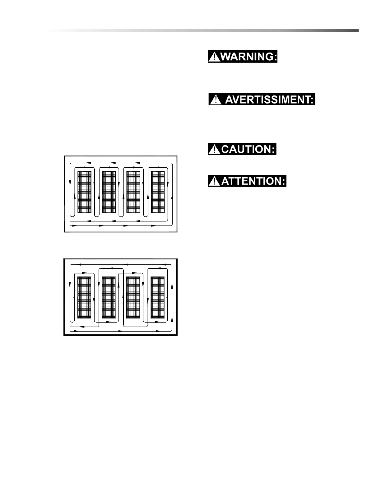
INEFFICIENT SCRUBBING PATH
RECOMMENDED SCRUBBING PATH
Normal Scrubbing
Plan the scrubbing pattern in advance. The longest
track is around the perimeter of the area to be cleaned.
For efficient operation, the runs should be the longest
possible without turning, stopping, or raising and
lowering scrub deck/squeegee.
NOTE: In order to achieve the best possible results, the
area which is to be cleaned should be swept before
scrubbing. Large debris, strings & wire must be
removed to prevent being caught in brushes or
squeegee.
To Begin Scrubbing
When operating the machine around people, pay
close attention for unexpected movement. Use
extra caution around children.
Lorsque vous utilisez la machine en présence de
gens, portez une attention particulière aux
mouvements inattendus. Soyez plus prudent,
surtout en présence d’enfants.
Flammable liquids and/or reactive metals can
cause explosions or fire! Do not pick up.
Les liquides inflammables et / ou les métaux
réactifs peuvent provoquer des explosions ou un
incendie ! Ne les ramassez pas.
1. Turn the machine power on.
2. Lower the squeegee.
3. Turn the vacuum on.
4. Lower the scrub brushes to the floor.
5. Turn the scrub brushes on (brushes will start when
machine is propelled).
6. Drive machine forward to begin scrubbing.
NOTE: Shut machine off immediately if water or foam
is expelled from the machine.
7. Adjust the speed of the machine, solution flow
and scrub brush pressure as necessary.
NOTE: Once solution flow rate is set it is not
necessary to shut off solution when stopping
scrubbing. Solution flow is automatically shut off
when brush motors stop. When brush motors are
activated, flow automatically resumes.
To Stop Scrubbing
1. Release the propel levers.
2. Turn the scrub brushes off.
3. Raise the scrub brushes.
86400370 Manual Operators - EURO 24V Standard
4. Raise the squeegee.
5. Turn the vacuum off.
6. Turn the machine power off.
19
Page 20
Operations
SOLUTION
TANK COVER
RECOVERY
TANK COVER
RECOVERY
TANK DRAIN
SOLUTION
TANK DRAIN
Machine Operation - Continued
Double Scrub
For floors which are heavily soiled or have thick accumulations of floor finish may not clean sufficiently with
one pass. In these cases it will be necessary to double
scrub.To double scrub, make the first pass over the
surface being cleaned with the squeegee up, vacuum
off, the solution on, Aqua-Mizer removed and brushes
down. This allows the solution to stay incontact with the
soil while loosening the surface accumulation with the
brushes. Allow time for the first application to stay in
contact with the floor. Length of time between the first
and second pass depends on amount of accumulation
and the type of chemical being used. A second
scrubbing with the squeegee down and again the
solution and brushes on will further loosen soil. The
additional application of solution will further assist the
difficult cleaning job.
FOR SAFETY: When using machine, go slow on
inclines and slippery services.
Emptying And Cleaning Tanks
86400370 Manual Operators - EURO 24V
Standard
Recovery Tank
1. Unhook the large drain hose from the retainer.
Unscrew the T-handle on plug enough to loosen
plug, then lower hose in direction of the drain. Do
not stand in front of end of hose. Recovered
solution will come out with force. Slowly remove
plug from drain hose.
2. Remove the recovery tank dome. Flush the
recovery tank out with clean water. Do not use
water hotter than 140°F (60°C) to clean tank.
Damage may occur.
3. Clean off the float shut-off system and inspect for
free movement of float. The float shut-off system is
located in the rear of the recovery tank.
4. Replace the drain plug and secure drain hose in
bracket.
5. If machine is to be stored, leave the recovery tank
dome off.
1. Park the machine next to a floor drain. Drain hose
2. Turn the machine power off and set parking brake,
Solution Tank
1. Loosen small drain hose from the retainer, then
2. Remove the solution tank cover.
3. Flush the solution tank out with clean water and
NOTE: Never allow solution to remain in tank.
Damage to tank, seals and valves could occur.
4. Secure drain hose into the retainer.
is on left rear corner of the machine.
if your machine is equipped with this option.
lower hose in direction of the drain.
run several gallons of clean water through
systems. Do not use water hotter than 140°F
(60°C) to clean tank. Damage may occur.
20
86400370 Manual Operators - EURO 24V Standard
Page 21

Service Schedule
Maintenance
MAINTENANCE DAILY WEEKLY MONTHLY
Check batteries after charging; add water if
necessary *
Check pad wear to prevent buildup of chemicals *
Check linkages and connectors for wear and
damage *
Check hoses for wear, blockages, or damage *
Clean squeegee; check for adjustment; inspect for
wear *
Check handles, switches, knobs, domes, and
gaskets for damage *
Clean out recovery tank *
Clean out solution tank; remove and clean screen *
Clean outside of all tanks; check for damage *
Run vac motor for at least one minute to allow
motor to dry *
Store with dome off tank to allow the tank to dry *
Check scrub deck splash skirt *
Check batteries for corrosion, cracks and evidence
of overheating
Check all bearings for noise *
Check all gaskets for wear and leakage *
Check vac motor carbon brushes *
Check brushes for wear; ensure bristles are not
damaged
Check linkages for wear and damage *
Grease wheels and casters *
Check squeegee blades for wear and frame for
damage
Check overall performance of machine *
Clean batteries and terminals *
Check parking brake (inspect cables, linkages and
pulleys) *
Check carbon brushes in all vacuum, brush drive,
and propel motors *
Blow out dust in motors *
Inspect motor commutators *
Clean chains, cables and pulleys *
Clean pivot points on squeegee and scrub deck
linkages *
*
*
*
100
HRS
200
HRS
86400370 Manual Operators - EURO 24V Standard
21
Page 22
Maintenance
1
7
10
4
3
11
5
8
6
9
Batteries
1. Batteries
2. Squeegee
3. Aqua-Mizer™
4. Scrub Brushes
5. Recovery Tank Float Shut-Off
6. Solution Strainer
7. Brush Motor
8. Traction Motor
9. Circuit Breakers
10. Brush Shroud & Brush Skirts
11. Vacuum Motor
22
86400370 Manual Operators - EURO 24V Standard
Page 23
1. Batteries
Maintenance
The batteries provide the power to operate the
machine. The batteries require regular maintenance to
keep them operating at peak efficiency.
The machine batteries will hold their charge for long
periods of time, but they can only be charged a certain
number of times. To get the greatest life from the
batteries, charge them when their charge level reaches
25% of a full charge. Use a hydrometer to check the
charge level.
Do not allow the batteries to remain in a discharged
condition for any length of time. Never expose a
discharged battery to temperatures below freezing.
Discharged batteries will freeze causing cracked
cases. Do not operate the machine if the batteries are
in poor condition or if they have a charge level below
25% (specific gravity below 1.155).
Keep all metallic objects off the top of the batteries, as
they may cause a short circuit. Replace worn or
damaged cables and terminals.
Check the electrolyte level in each battery cell before
and after charging the batteries. Never add acid to the
batteries, use distilled water. Do not allow water level to
fall below the battery plates. Portions of plates exposed
to air will be destroyed. Do not overfill. Keep plugs
firmly in place at all times.
Les batteries émettent du gaz hydrogène. Une
explosion ou un incendie peut en résulter.
Maintenez les étincelles et les flammes nues à
l’écart. Gardez les carters ouverts lors du chargement.
Wear eye protection and protective clothing when
working with batteries.
Portez des lunettes de protection et des vêtements
de protection lorsque vous travaillez avec des
batteries.
Charge batteries in a well ventilated area.
Chargez les batteries dans un endroit bien ventilé
Battery Maintenance
1. When cleaning the batteries, use a solution of
baking soda and water. Do not allow the cleaning
fluid to enter the battery cells, electrolyte will be
neutralized.
2. Maintain the proper electrolyte level in e ach battery
cell. If a cell should accidentally overflow, clean
immediately.
3. Wipe off the top of the batteries at least once a
week.
When servicing machine, avoid contact with
battery acid.
Lors de l'entretien de la machine, évitez tout
contact avec l'acide de batterie.
Batteries emit hydrogen gas. Explosion or fire can
result. Keep sparks and open flame away. Keep
covers open when charging.
86400370 Manual Operators - EURO 24V Standard
4. Test battery condition with a hydrometer at least
once a week.
5. Ensure that all connections are tight and all
corrosion removed.
6. Every 4 to 6 months, remove that batteries from
the machine and clean the battery cases and
battery compartment.
23
Page 24
Maintenance
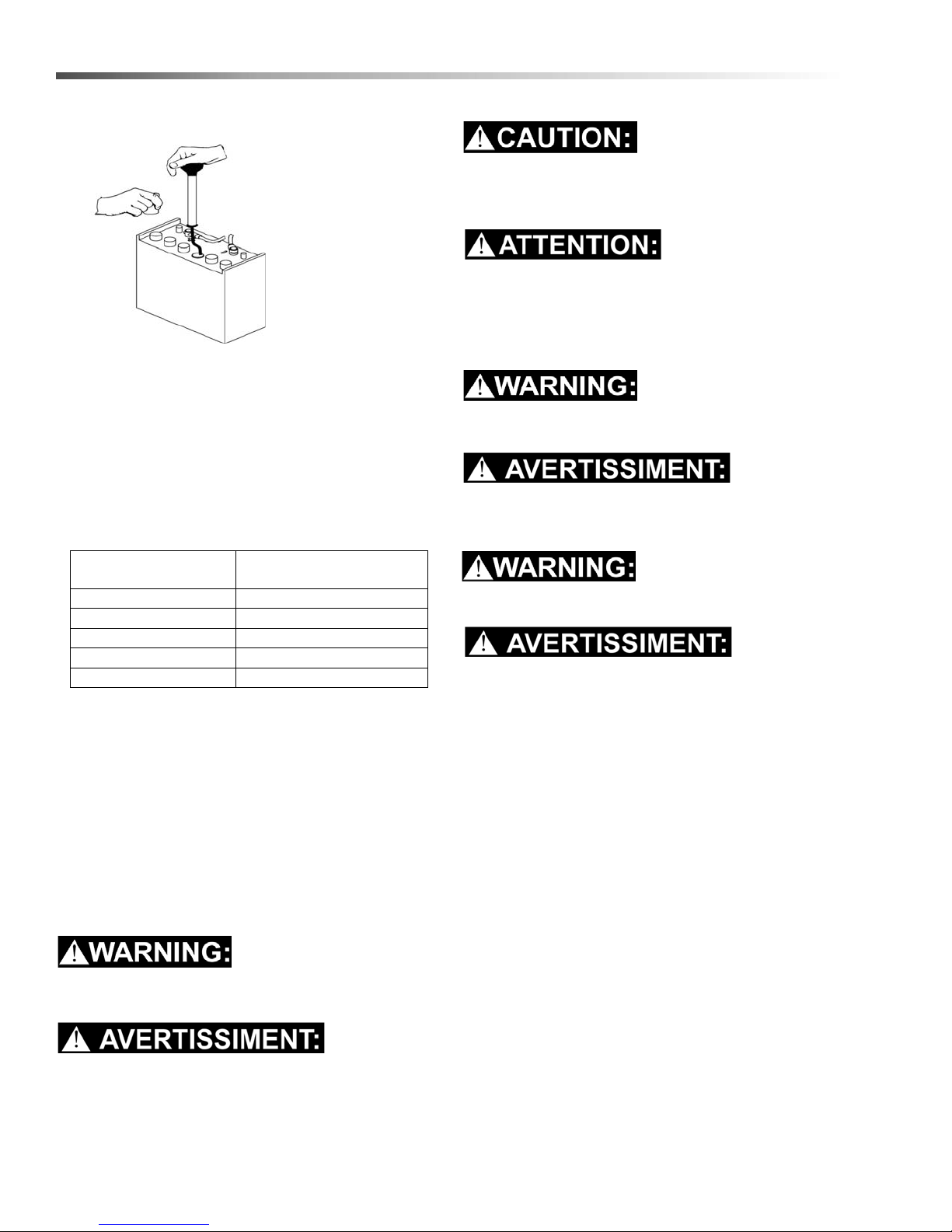
Checking Battery Specific Gravity
Use a hydrometer to check the battery specific gravity.
Checking Gravity
Batteries emit hydrogen gas. Explosion or fire
can result. Keep sparks and open flame away.
Keep covers open when charging.
Les batteries émettent du gaz hydrogène. Une
explosion ou un incendie peut en résulter.
Maintenez les étincelles et les flammes nues à
l’écart. Gardez les carters ouverts lors du chargement.
A. Hydrometer
B. Battery
NOTE: Do not take readings immediately after adding
distilled water, if the water and acid are not
thoroughly mixed, the reading may not be accurate.
Check the hydrometer readings against this chart.
SPECIFIC GRAVITY
@ 80° F (27°C)
1.265 100% CHARGED
1.225 75% CHARGED
1.190 50% CHARGED
1.155 25% CHARGED
1.120 DISCHARGED
NOTE: If the readings are taken when the battery
electrolyte is any temperature other than 80
(27
°C), the reading must be temperature corrected.
To find the corrected specific gravity reading when the
temperature of the battery electrolyte is other than
80
°F (27°): Add (+) to the specific gravity reading 0.004
(4 points), for each 10
Subtract (-) from the specific reading 0.004 (4 points),
for each 10
°F (6°C) below 80°F (27°C).
BATTERY CONDITION
°F
°F (6°C) above 80° (27°C).
To Charge The Batteries
Wear eye protection and protective clothing when
working with batteries.
Portez des lunettes de protection et des vêt ements
de protection lorsque vous travaillez avec des
batteries.
Charge batteries in a well ventilated area. Leave
the battery cover open.
Chargez les batteries dans un endroit bien ventilé
Use a 24 volt, 18 amp maximum output or 25 amp
(depending on the size of the batteries), DC charger
which will automatically shut off when the batteries are
fully charged.
1. Stop the machine in a clean, well ventilated area
next to the charger.
2. Turn “OFF” machine.
FOR SAFETY: Before leaving or servicing
machine; stop on level surface, turn off machine
and remove key.
3. Raise the battery cover.
When servicing machine, avoid contact with
battery acid.
Lors de l'entretien de la machine, évitez tout
contact avec l'acide de batterie.
24
86400370 Manual Operators - EURO 24V Standard
Page 25
Batteries emit hydrogen gas. Explosion or fire can
FRONT OF MACHINE
result. Keep sparks and open flame away. Keep
covers open when charging.
Les batteries émettent du gaz hydrogène. Une
explosion ou un incendie peu t en résu lt er.
Maintenez les étincelles et les flammes nues à
l’écart. Gardez les carters ouverts lors du chargement.
4. Check the electrolyte level in each battery cell.
Before charging, add just enough distilled water to
cover the plates. After charging is complete, add
just enough distilled water to bring up the level to
the indicator ring. If the water level is too high
before charging, normal expansion rate of the elec trolyte may cause an overflow. Resulting in a loss
of battery acid balance and damage the machine.
Maintenance
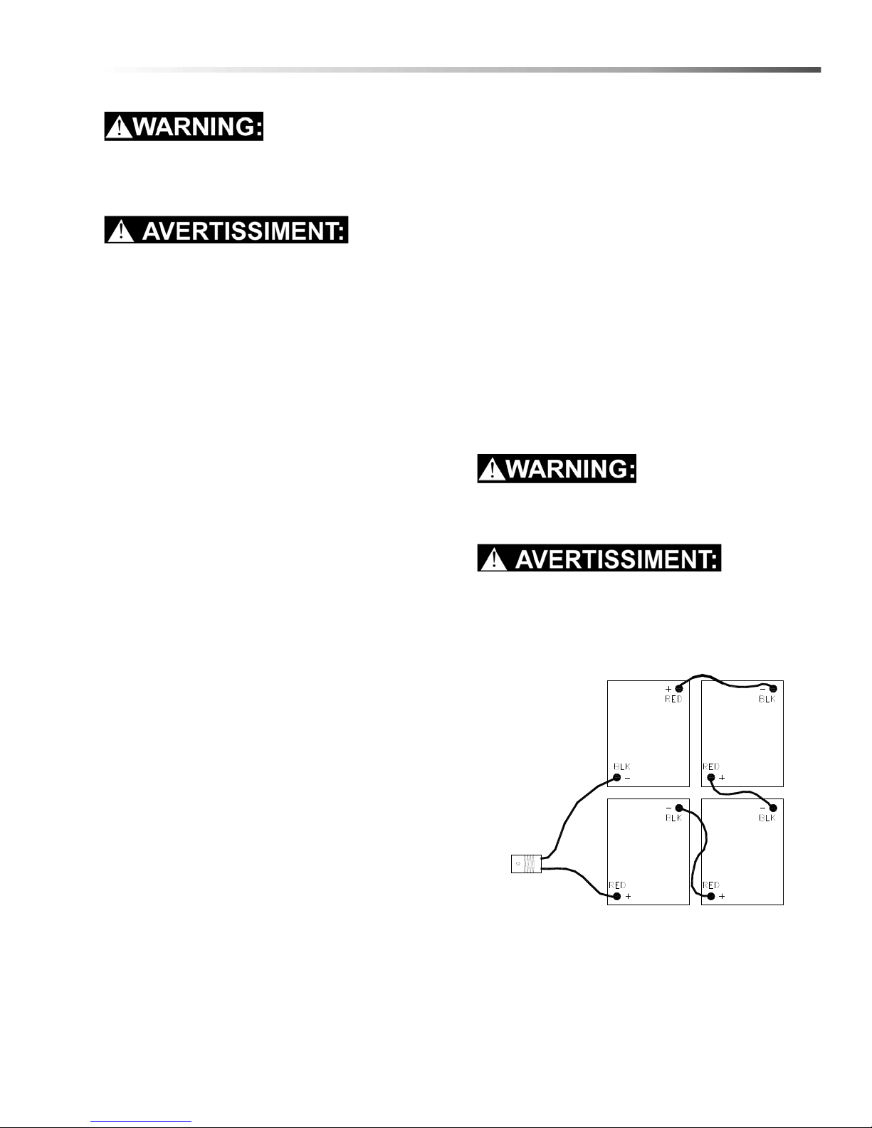
Changing Batteries
Stop the machine in a clean area next to the charger .
Turn off machine.
FOR SAFETY: Before leaving or servicing the
machine; stop on level surface, turn off machine
and remove key.
1. Raise the battery cover.
2. Disconnect battery pack from machine.
3. Use the proper size open end wrench to disconnect main ground wire first and secure cable
terminal away from batteries.
4. Disconnect main positive lead and secure cable
terminals away from batteries.
5. Loosen both terminals on each jumper cable and
remove one at a time.
6. Prepare a suitable site to place the batteries.
7. Attach suitable battery lifting device and lift
batteries from the machine.
5. Replace the battery caps, and leave them in place
while charging.
6. Unplug the battery connector from the machine.
FOR SAFETY: When charging, connect the
charger to the batteries before connecting the
charger to the AC wall outlet. Never connect the
charger to the AC wall outlet first. Hazardous
sparks may result.
7. Plug the charger connector into the battery
connector. Connect the charger AC plug to a wall
outlet. The charger gauge should indicate that the
batteries are charging.
8. When the batteries are fully charged, disconnect
the charger from the AC wall outlet, then disconnect the charger from the batteries.
9. Connect the batteries to the machine connector.
10. Check the electrolyte level. It should be up to the
indicator ring. If necessary, add distilled water.
11. Lower the battery cover.
Batteries are a potential environmental hazard.
Consult your battery supplier for safe disposal
methods.
Les batteries constituent un danger potentiel pour
l'environnement. Consultez le fournisseur de votre
batterie pour connaître les méthodes d'élimination
sûres.
86400370 Manual Operators - EURO 24V Standard
25
Page 26

Maintenance
SIDE VIEW OF SQUEEGEE BLADE
SQUEEGEE DEFLECTION
TOO MUCH
CORRECT
NOT ENOUGH
2. Squeegee Blades
The front squeegee blade allows solution to pass
through channels in the blade into the squeegee
assembly while maintaining vacuum to provide lift. The
front blade has four wear surfaces and can be rotated
for extended life. The front blade should not require
regular replacement under normal use.
The rear blade wipes the floor to a near dry condition. It
is important the rear blade be in good condition to
properly do its job. As with the front, each squeegee
blade assembly has four wear surfaces for extended
service.
Check both the front and rear squeegee blades for
damage, wear, and adjustment each day in the pre-run
check. Change the front blade if it is torn or has an
uneven edge. Change the rear blade if it is less than
1/2 the original thickness.
Adjusting Squeegee
Adjusting the squeegee is a two-part process. First, the
squeegee assembly must have correct pitch in order for
the squeegee blade to have the same deflection at
each tip as well as the center. The knob on the
squeegee linkage controls the pitch adjustment. The
second adjustment is the deflection. Knobs on each
end of the squeegee control this.
To Remove Squeegee Assembly
1. With the squeegee in the up position, turn key
switch “OFF”.
FOR SAFETY: Before leaving or servicing
machine; stop on level surface, turn off machine
and remove key.
2. Disconnect vacuum hose from squeegee and
loosen both knobs.
3. Pull squeegee assembly rearward from the lifting
carrier.
4. Inspect or repair as necessary and reinstall.
To Replace Or Rotate Rear Squeegee
Blades
1. With the squeegee in the up position, turn key
switch “OFF”.
FOR SAFETY: Before leaving or servicing
machine; stop on level surface, turn off machine
and remove key.
2. Remove the squeegee assembly from the
machine. Unlatch and remove blade retainer strap
and remove squeegee blade.
3. Rotate the squeegee to new edge position or
replace as required. Each blade has four new edge
positions.
4. Install blade on locating pins of squeegee
assembly.
26
5. Install squeegee retainer strap.
6. Fasten and lock latch, adjust latch only tight
enough to take up slack in retaining strap.
To Replace Or Rotate Front Squeegee
Blade
1. With the squeegee in the up position, turn key
switch “OFF”.
2. Remove the squeegee from the machine. Loosen
three thumbscrews and remove the retainer strap
and squeegee blade.
3. Rotate the squeegee to new edge position or
replace as required. Each blade has four new edge
positions. When installing the front blade, tighten
the center thumbscrew first. Insure that the retainer
strap is pressed against the blade before tightening
the outer screws.
86400370 Manual Operators - EURO 24V Standard
Page 27

Maintenance
SIDE VIEW OF SQUEEGEE BLADE
SQUEEGEE DEFLECTION
CORRECT
3
8
"
(9.5mm)
To Adjust Squeegee Pitch
1. Choose a smooth, level surface. Turn “ON” the key
switch. Lower the squeegee and drive forward at
least 2 feet (60cm.).
2. With the squeegee down, stop the machine. Do not
allow machine to roll back.
FOR SAFETY: Before leaving or servicing the
machine; stop on level surface, turn off machine
and remove key.
3. Determine the differences, if any, in deflection of
the squeegee blade between each end and the
middle. Proper adjustment is obtained when
deflection is equal all the way across the squeegee
blade. The bubble level should also indicate when
the squeegee is adjusted properly. When the air
bubble is in the center of the vial, the deflection
should be even across the squeegee blade.
4. To decrease the deflection of the squeegee blade
at the ends, tighten knob near the squeegee
center. To increase the deflection at the ends of the
squeegee assembly, loosen knob.
5. Check the deflection of the squeegee blades
again. Repeat steps 1 through 4 until the deflection
is equal across the entire rear squeegee blade.
To Adjust Amount Of Rear Squeegee
Deflection
1. Choose a smooth, level surface. Lower the
squeegee and drive forward at least 2 feet (60cm).
2. With the squeegee down, stop the machine. Do not
allow machine to roll back.
FOR SAFETY: Before leaving or servicing
machine; stop on level surface, turn off machine
and remove key.
3. Observe the amount of squeegee deflection. It
should deflect 3/8 in. (9.5mm) across the entire
width of the squeegee.
4. To increase the squeegee deflection, turn the 2
knobs at the squeegee ends counter-clockwise. To
decrease the deflection, turn the knobs clockwise.
NOTE: The deflection should be consistent along the
length of the squeegee. If the deflection varies from
end to end the knobs can be adjusted independently
to correct the variation.
5. Turn on the key switch. Raise, then lower
squeegee assembly. Drive forward at least 2 feet
(60cm).
6. Repeat steps 2 through 4 until deflection of 3/8 in.
(9.5mm) is reached.
3. To Replace Aqua-Mizer™ Squeegee
Blades
These squeegee blades have two wear edges. To use
the second edge:
1. Remove deck shrouds.
2. Remove brushes or pad drivers.
3. Remove each of the Aqua-Mizer™ squeegee
systems.
4. Remove the hardware from each system that
retains the blade.
5. Flip the blades and replace hardware.
6. Re-install each Aqua-Mizer™ system, brushes or
pad drivers and shrouds.
86400370 Manual Operators - EURO 24V Standard
27
Page 28

Maintenance
4. Scrub Brushes
There are four different types of brushes available to
cover applications from cleaning heavily soiled floors to
polishing. A pad driver is also available to take
advantage of the many cleaning pads on the
market.Please refer to the following to assist in
selecting the proper brush or pad for the work at hand.
Uncoated Floors
Aggressive Grit is a nylon fiber impregnated with
silicone carbide grit. It grinds away stain, soil, and
removes surface material.
Mild Grit is a less aggressive silicone carbide grit
suitable for cleaning medium soil conditions.Advantages are faster ground speed than nylon bristles on
light solid applications.
Polypropylene is a general-purpose scrub brush with
stiff bristles. Polypropylene works well for maintaining
concrete, wood and tile floors.
Finished Floors
Nylon bristles are used in a variety of applications on
coated or uncoated surfaces.
White Pads (Polishing) are used for dry polishing to
achieve a high-gloss appearance, or surface washing
on highly polished or burnished floors.
Red Pads (Buffing) are used for light-duty scrubbing.When used with a mild detergent they will provide
surface cleaning without removing the finish.
Blue Pads (Scrubbing) are used for heavy-duty
scrubbing and light stripping. The blue pads remove
less finish than brown stripping pads, yet will remove
black marks, stains and dirt.
Black Pads (Strippin g) are used for easy and complete
removal of old floor waxes/finishes. They will quickly
remove ground in dirt, black heel marks, and
spills.When used with the proper stripper, this pad
leaves the floor clean and ready for finishing.
Replacing Or Installing Scrub Brushes
1. With the scrub deck up, turn “OFF” the machine.
FOR SAFETY: Before leaving or servicing the
machine; stop on level surface, turn OFF machine
and remove key.
2. Remove the brush cover shrouds.
3. Locate release lever on top of brush or pad
driver.Rotate release lever counter-clockwise and
the brush/pad driver will release and drop down.
4. To reinstall, center the brush driver under the brush
drive hub. Raise until it contacts brush driver
assembly. Turn clockwise until release lever plate
locks into position.
5. Replace the brush cover shrouds.
NOTE: Check that release plate is completely closed
and pad/brush is securely attached. Da mage to driver
or brush could occur.
5. Recovery Tank Float Shut-off
When water is no longer being vacuumed from the
floor and the vacuum fan is operating, the ball float
has engaged. The vacuum motor will not vacuum
water with recovery tank full. The recovery tank
must be drained.
1. The float shut-off screen can be cleaned in or out
of the machine.
2. To clean the float shut-off while it is inside the
machine wipe material off screen then rinse. Check
that the ball is also clean and moves freely.
3. To remove the float shut-off, grasp the screen with
one hand and the connected tube with the other.Tilt
and pull the float screen assembly to pull it off the
barb on the tube.
4. To install, place one hand on the tube, and then tilt
and push the float screen assembly over the barb
on the tube.
The scrub brushes should be checked before each
days work for wire, string, wear and damage.
28
86400370 Manual Operators - EURO 24V Standard
Page 29

Maintenance
6. Solution Strainer
The solution strainer is located in front of the left front
wheel. The solution strainer protects the solenoid valve
from debris. If there is little or no solution flow to the
ground, check the strainer for debris. Drain the solution
tank and clean the solution strainer. To remove the
strainer, turn the bottom part of the strainer counterclockwise until the bottom is separated. Clean out the
debris from the wire mesh and re-assemble. Make sure
the O-ring gasket is in place when re-assembled
.
7. Brush Motor
Do not use a pressure washer to clean around the
brush motors. Use tap pressure only.
N’utilisez pas de nettoyeur haute pression pour
nettoyer autour des moteurs des brosses. Utilisez
seulement la pression du robinet.
Changing Brush Motors
1. With the scrub deck in the stored position, disconnect brush motor wiring connector from harness.
2. Remove shrouds from scrub deck to access and
remove scrub brushes or pad drivers.
3. Remove retaining bolt, lock washer, flat washer
and star drive from brush motor shaft.
4. Remove 4 brush motor mounting bolts located
under scrub deck.
5. Remove brush motor.
Brush Motor Carbon Brush Replacement
1. Scribe alignment mark on motor barrel to motor
cap. Remove two bolts.
2. Remove end cap from motor.
NOTE: Motors contain two wave washers in cap. Do
not lose these.
3. Release brush from spring tension. Remove screw
connecting brush wire lead to brush holder. Clean
brush holder to insure free movement.
4. Retract spring and install new brush. Install
connector screw and lead.
5. When all new brushes are installed. Place all in
retracted position, held into brush holder by spring
tension.
6. Carefully place end cap onto bearing on motor
shaft.
NOTE: Use care to assure wave washer alignment.
7. With end cap in partially installed position, release
all brushes to contact position with motor commutator.
NOTE: Failure to insure all brushes are released will
result in motor failure.
8. Reset end cap and realign with scribe marks on
motor barrel. Reinstall the two attach bolts from
cap into base.
9. Maintain alignment between motor barrel base and
cap.
6. Reverse steps to install.
86400370 Manual Operators - EURO 24V Standard
29
Page 30

Maintenance
30 Amp. Protects the right scrub
brush motor.
30 Amp. Protects the left scrub
brush motor.
25 Amp. Protects the vacuum
motor.
25 Amp. Protects the propel motor.
3 Amp. Protects the machine
controls.
8. Traction Motor
Do not use a pressure washer to clean around the
motors. Use tap pressure only.
N’utilisez pas de nettoyeur haute pression pour
nettoyer autour des moteurs des brosses. Utilisez
seulement la pression du robinet.
Traction Motor Carbon Brush
Replacement
FOR SAFETY: Before leaving or servicing
machine, stop on a level surface, turn off machine
and remove key.
1. Disconnect batteries from machine.
2. Disconnect the electrical connection to the traction
motor.
3. Remove brush cap.
4. Release brush from spring tension. Remove screw
connecting brush wire lead to brush holder. Clean
brush holder to insure free movement.
9. Circuit Breakers
Circuit breakers interrupt the flow of power in the event
of an electrical overload. When a circuit breaker is
tripped, reset it by pressing the exposed button. If a
circuit breaker continues to trip, the cause of the electrical overload should be found and corrected.
5. Install new brush and reinstall connecting screw
and lead.
6. When all new brushes are installed. Place all in
retracted position, held into brush holder by spring
tension.
7. Carefully replace brush cap onto bearing on motor
shaft.
10.Brush Shrouds & Brush Skirts
Contain the water in the shroud area. The skirt will flex
over uneven floors and also as the brush or pad wears.
As the brush wears the shrouds can be adjusted so that
skirt does not have to flex so much.
Remove three bolts on each side that fasten the
bracket to the cover and re-assemble in the top
holes.When the brushes are replaced with new ones
move the covers back to the lower set of holes.
30
86400370 Manual Operators - EURO 24V Standard
Page 31

11.Vacuum Motor
3
8
[9.5mm]
Vacuum Motor Carbon Brushes
Carbon
Brushes
End Cap
If armature commutator is grooved, extremely pitted or not
concentric, the motor will need to be replaced or sent to a
qualified service center.
Important:
These brushes wear quicker as the length shortens due to
increased heat. Spring inside brush housing will damage
motor if brushes are allowed to wear away completely.
Periodically check the length of the carbon brushes. Replace
both carbon brushes when either is less than 3/8" (9.5mm)
long.
(Refer to the Vacuum Group in the parts section of
manual)
Do not use a pressure washer to clean around the
vacuum motors. Use tap pressure only. Care must
be taken so that water is not directed into vacuum
motor air intakes.
Ne pas utiliser un jet d’eau à forte pression pour
laver autour des moteurs d’aspiration. N’utiliser
que la pression de l’eau du robinet. Veiller à ne pas
diriger l’eau sur les prises d’air des moteurs d’aspiration.
Changing V acuum Motor
1. Disconnect batteries from machine.
Maintenance
2. Remove front cover.
3. Disconnect electrical connector to the vacuum
motor.
4. Loosen clamp and disconnect hose from vacuum
intake.
5. Remove vacuum motor mounting bracket bolts.
6. Remove vacuum motor from mounting bracket.
7. Reverse steps to install.
86400370 Manual Operators - EURO 24V Standard
31
Page 32
Maintenance
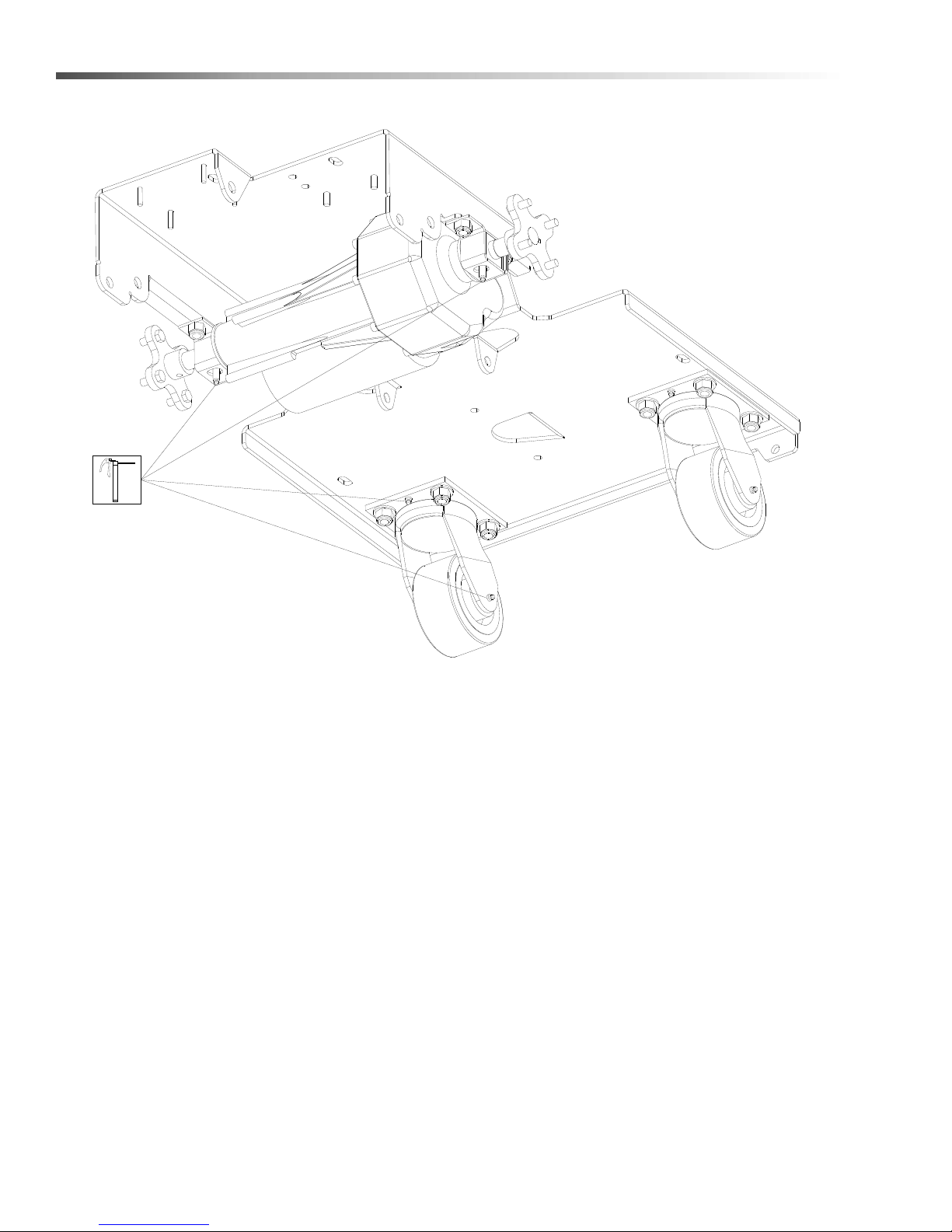
RECOMMENDED GREASING:
1-2 strokes of Mobiltemp®78 or compatible clay-based or
calcium-based grease.
NOTE: Use hand operated grease gun only.
Greasing Axle
32
86400370 Manual Operators - EURO 24V Standard
Page 33

Troubleshooting
PROBLEM CAUSE SOLUTION
Maintenance
Squeegee out of adjustment Adjust squeegee
Debris caught on squeegee Remove debris
Worn squeegee blades Rotate or replace squeegee
blades
Vacuum hose clogged Clear obstruction from hose
Poor or no water pick-up
Vacuum motor does not run, or runs
slowly
Poor scrubbing performance
Vacuum hose disconnected
Reconnect vacuum hose
from squeegee or recovery
tank
Vacuum hose damaged Replace vacuum hose
Recovery tank not sealed Place recovery tank dome on
tank. Replace damaged
gaskets.
Foam filling recovery tank Empty recovery tank
Use less or different
detergent
Use defoamer
Recovery tank full Drain recovery tank
Recovery tank float system
Clean float system
dirty
Circuit breaker tripped Reset circuit breaker
Loose connection Check motor wires and
connections
Faulty vacuum switch Replace switch
Worn vacuum motor brushes Replace brushes, check
commutator
Debris caught in scrub
Remove debris
brushes
Worn brushes or pads Replace brushes or pads
Improper detergent, brush or
pad used
Low scrub brush down
Contact equipment or
application specialist
Increase brush pressure
pressure
Low battery charge Charge batteries
Circuit breaker(s) tripped Reset circuit breaker(s)
Brush motors do not run, or runs
slowly
86400370 Manual Operators - EURO 24V Standard
Loose connection Check motor wires and
connection
Faulty brush motor contactor Replace contactor
Worn brush motor brushes Replace brushes, check
commutator
33
Page 34

Maintenance
Machine Troubleshooting - Continued
PROBLEM CAUSE SOLUTION
Solution tank empty Fill solution tank
Solution flow turned off or set too
low
Solution strainer plugged Clean solution strainer
Little or no solution flow to the floor
No power to machine
Little or no propel
Solution hoses obstructed Clear obstruction from hose
Solution solenoid valve
obstructed or stuck
Vent hole in solution tank lid
obstructed
Battery disconnected Check all battery cable
Emergency shut-off activated (If
included)
Battery connections corroded Clean connections
Faulty main contactor Replace contactor
Faulty key switch Replace switch
Low battery charge Charge batteries
Wheels spin Decrease brush pressure
Controller overheated Allow cool down period
Loose connection Check motor wires and
Turn on or increase flow setting
Clean or replace
Clear obstruction from vent hole
connections
Reset
Adjust brush shroud if needed
connection
34
86400370 Manual Operators - EURO 24V Standard
Page 35
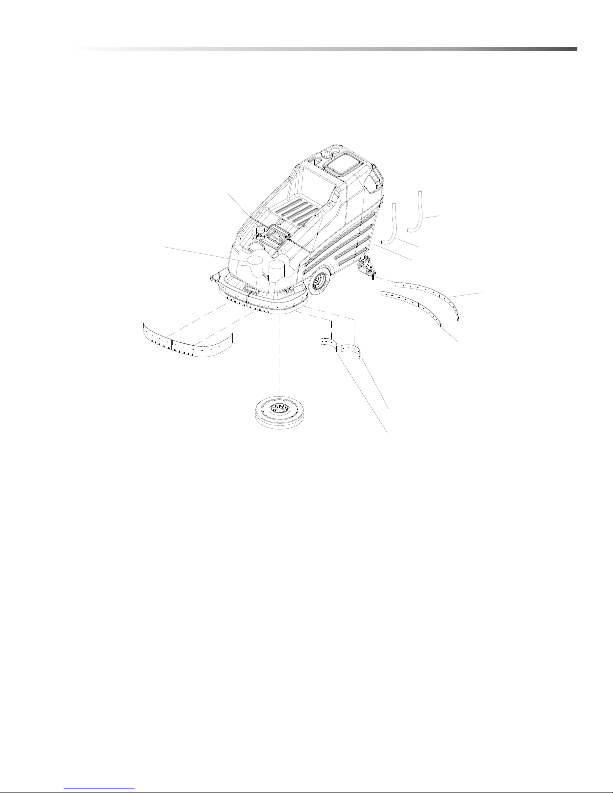
Suggested Spare Parts
86066380 SKIRT 26 IN LEFT
86007450 SKIRT 26 IN RIGHT
86001410 BLADE LEFT 13 IN
86001400 BLADE RIGHT 13 IN
86007430 SQUEEGEE
REAR BLADE LINATEX
86008020 SQUEEGEE
FRONT BLADE LINATEX
86282050 SOLUTION HOSE
86004180 RECOVERY HOSE
86326980 BRUSH SET
VACUUM
86000220 BRUSH 13" POLYPROPYLENE SD U19880
86000230 BRUSH 13" NYLON SD U19981
86000240 BRUSH 13" MILD GRIT SD U19982
86001360 BRUSH SET
SCRUB DECK MOTOR
86004260 DRAIN HOSE
86137020 SQUEEGEE
REAR BLADE URETHANE
86137030 SQUEEGEE
FRONT BLADE URETHANE
86135150 BLADE LEFT 13 IN URETHANE
86135140 BLADE RIGHT 13 IN URETHANE
86400370 Manual Operators - EURO 24V Standard
35
 Loading...