

Page 1
A
SCRUBBER
MODELS: SGJ32
10052530
FTER SN: 1000136404
PRV
Operating Instructions
Read these instructions before using the machine
N
86037680 11/05/08
PRV NO. 980230
Page 2

MACHINE DATA LOG/OVERVIEW
Name: __________________________________________________________________________________________________
Address: _______________________________________________________________________________________________
Phone Number: _________________________________________________________________________________________
MODEL _______________________________________
DATE OF PURCHASE __________________________
SERIAL NUMBER ______________________________
SALES REPRESENTATIVE # _____________________
DEALER NAME ________________________________
OPERATIONS GUIDE NUMBER ___________________
PUBLISHED
__________________________________________
YOUR DEALER
For the name and address of your dealer contact: Windsor Industries
OVERVIEW
The Saber Glide is a battery powered, ride-on, hard floor scrubber intended for commercial use.
The appliance applies a cleaning solution onto a hard floor, scrubs the floor with brushes or pads,
and then vacuums the soiled water back into the recovery tank.
SGJ32 86037680 01/03/07
2
Page 3

3
Machine Data Log/Overview................................2
Table of Contents.................................................3
HOW TO USE THIS MANUAL
How to use this Manual........................................1-1
SAFETY
Important Safety Instructions ...............................2-1
Hazard Intensity Level..........................................2-2
Safety Label Location...........................................2-3
OPERATIONS
Technical Specifications.......................................3-1
How the Machine Works......................................3-3
Components.........................................................3-4
Controls................................................................3-5
Machine Operation............................................ 3-14
Pre-Run Machine Inspection ......................... 3-14
Starting Machine............................................ 3-14
Filling the Solution Tank.................................3-14
Scrubbing....................................................... 3-14
Emergency Stop Procedures......................... 3-15
Emptying & Cleaning Tanks........................... 3-16
MAINTENANCE
Maintenance............................................ ............4-1
Batteries...............................................................4-2
Battery Maintenance............................................4-2
Checking Battery Specific Gravity.....................4-2
Charging the Batteries. .....................................4-3
Changing Batteries............................................4-4
Battery Connections..........................................4-4
Squeegee.............................................................4-5
Adjusting Pitch ..................................................4-5
Replace/Rotate Rear Squeegee Blade.............4-6
Removing Squeegee Assembly........................4-6
Replace/Rotate Front Squeegee Blade............4-6
Side Squeegee..................................................4-7
Replace/Rotate Side Squeegee Blades............4-7
Adjusting the Side Squeegee Deflection...........4-7
Scrub Brush Replacement...................................4-8
Brake....................................................................4-9
Steering Chain Tensioner ....................................4-9
Vacuum Motor................................................... 4-10
Brush Motor....................................................... 4-11
Traction Motor................................................... 4-12
Fuse ..................................................................4-12
Circuit Breakers................................................. 4-12
Squeegee Actuator ...........................................4-13
Scrub Deck Actuator......................................... 4-14
Transporting Machine .......................................4-15
Jacking Machine ............................................... 4-16
TABLE OF CONTENTS
Service Schedule. .............................................4-17
Machine Troubleshooting..................................4-18
GROUP PARTS LIST
Brake....................................................................5-1
Circuit Breaker......................................................5-3
Control Panel........................................................5-5
Decal. ...................................................................5-7
Front Bumper & Floor...........................................5-9
Fwd/Rev Pedal..................................................5-11
Scrub Brush/Driver............................................5-13
Scrub Deck Lift-32 in.........................................5-15
Scrub Deck-32 in...............................................5-17
Scrub Deck Side Squeegee-32 in..................... 5-19
Seat & Side Cover.............................................5-21
Solution Delivery ...............................................5-23
Squeegee –32 in...............................................5-25
Squeegee Lift....................................................5-27
Steering-Upper..................................................5-29
Steering-Lower..................................................5-31
Tank ..................................................................5-33
Tank Cover........................................................5-35
Vacuum.............................................................5-37
Wheel & Frame .................................................5-39
Wiring-Battery....................................................5-41
Wiring-Main Harness.........................................5-43
Wiring-Main Harness Connection .....................5-45
Wiring-Control Panel Group..............................5-47
Wiring-Drive Motor ............................................5-49
Wiring Diagram..................................................5-51
Suggested Spare Parts.....................................5-52
Serial Numbers..................................................5-53
SGJ32 86037680 11/05/08
Page 4
HOW TO USE THIS MANUAL
This manual contains the following sections:
- HOW TO USE THIS MANUAL
- SAFETY
- OPERATIONS
- MAINTENANCE
- PARTS LIST
The HOW TO USE THIS MANUAL section will tell
you how to find important information for ordering
correct repair parts.
Parts may be ordered from authorized Windsor
dealers.
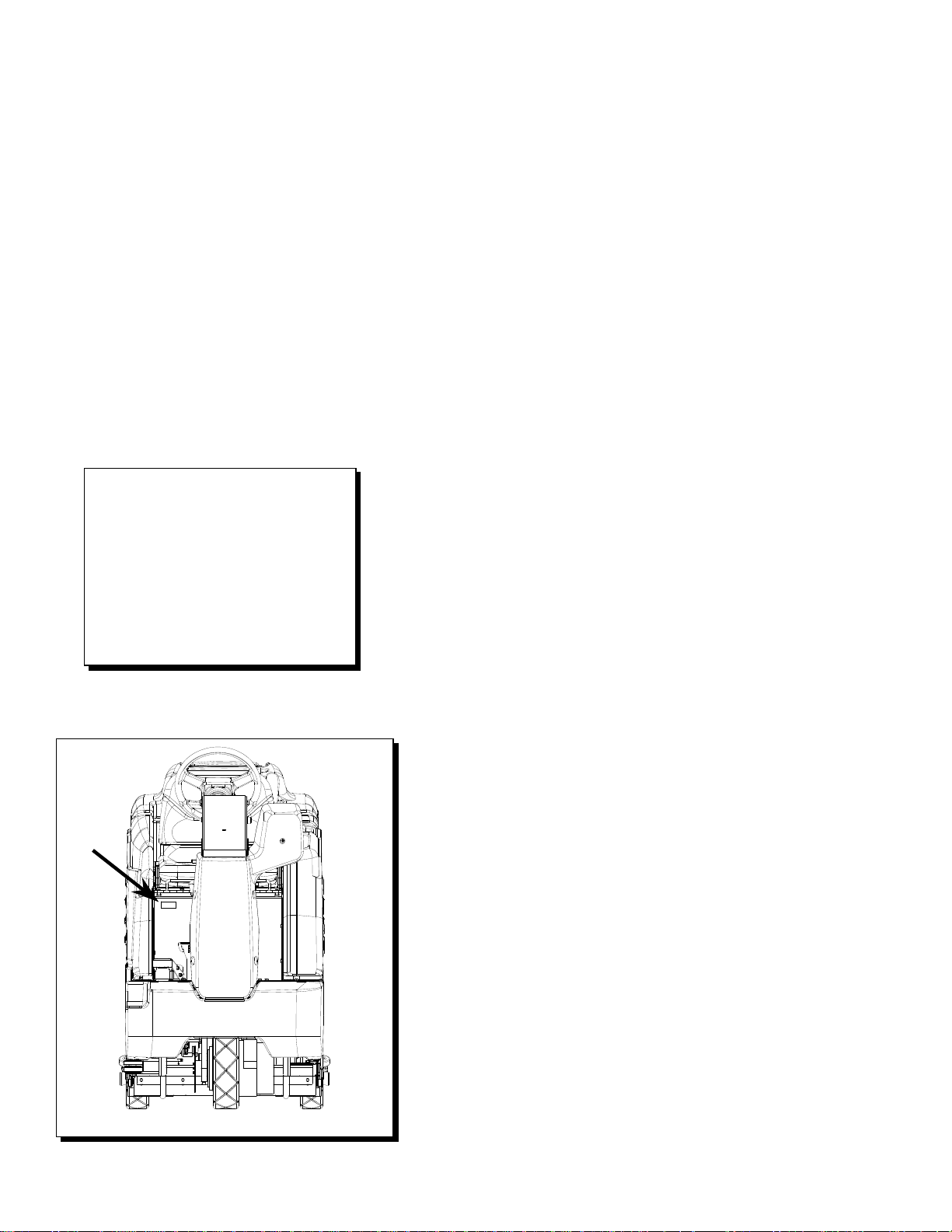
When placing an order for parts, the
machine model and machine serial number are
important. Refer to the MACHINE DATA box which
is filled out during the installation of your machine.
The MACHINE DATA box is located on the inside of
the front cover of this manual.
MODEL _____________________________________
DATE OF PURCHASE ________________________
SERIAL NUMBER ____________________________
SALES REPRESENTATIVE # ___________________
DEALER NAME ______________________________
OPERATIONS GUIDE NUMBER __________________
PUBLISHED ________________________________
Copyright 2002 Windsor Industries, Printed in USA
The model and serial number of your machine are
located to the front of the battery compartment for
the machine.
1-1
SGJ32 86037680 11/05/08
The SAFETY section contains important information
regarding hazard or unsafe practices of the
machine. Levels of hazards are identified that could
result in product or personal injury, or severe injury
resulting in death.
The OPERATIONS section is to familiarize the
operator with the operation and function of the
machine.
The MAINTENANCE section contains preventive
maintenance to keep the machine and its
components in good working condition. They are
listed in this general order:
- Batteries
- Scrub Brushes
- Adjusting Squeegee
- Service Schedule
- Machine Troubleshooting
The PARTS LIST section contains assembled parts
illustrations and corresponding parts list. The parts
lists include a number of columns of information:
- REF – column refers to the reference
number on the parts illustration.
- PART NO. – column lists the part
number for the part.
- PRV NO. – reference number
- QTY – column lists the quantity of the
part used in that area of the machine.
- DESCRIPTION – column is a brief
description of the part.
- SERIAL NO. FROM – If this column has
an (*) and a Reference number, see the
SERIAL NUMBERS page in the back of
your manual. If column has two asterisk
(**), call manufacturer for serial number.
The serial number indicates the first
machine the part number is applicable
to. The main illustration shows the most
current design of the machine. When a
boxed illustration is shown, it displays
the older design.
- NOTES – column for information not
noted by the other columns.
NOTE: If a service or option kit is installed on your
machine, be sure to keep the KIT INSTRUCTIONS
which came with the kit. It contains replacement
parts numbers needed for ordering future parts.
NOTE: The number on the lower left corner of the
front cover is the part number for this manual.
Page 5

IMPORTANT SAFETY INSTRUCTIONS
!
When using an battery powered appliance, basic precaution
must always be followed, including the following:
READ ALL INSTRUCTIONS BEFORE USING THIS MACHINE.
To reduce the risk of fire, electric shock, or injury:
WARNING:
Use only indoors. Do not use outdoors or expose to rain.
Use only as described in this manual. Use only manufacturer’s recommended components and
attachments.
If the machine is not working properly, has been dropped, damaged, left outdoors, or dropped into
water, return it to an authorized service center.
Do not operate the machine with any openings blocked. Keep openings free of debris that may reduce
airflow.
This machine is not suitable for picking up hazardous dust.
Machine can cause a fire when operating near flammable vapors or materials. Do not operate this
machine near flammable fluids, dust or vapors.
This machine is suitable for commercial use, for example in hotels, schools, hospitals,
factories, shops and offices for more than normal housekeeping purposes.
Maintenance and repairs must be done by qualified personnel.
If foam or liquid comes out of machine, switch off immediately.
Disconnect battery before cleaning or servicing.
Before the machine is discarded, the batteries must be removed and properly disposed of.
Make sure all warning and caution labels are legible and properly attached to the machine.
During operation, attention shall be paid to other persons, especially children.
Before use all covers and doors shall be put in the positions specified in the instructions.
When leaving unattended, secure against unintentional movement.
The machine shall only be operated by instructed and authorized persons.
When leaving unattended, switch off or lock the main power switch to prevent unauthorized use.
Only chemicals recommended by the manufacturer shall be used.
This appliance has been designed for use with the brushes specified by the manufacturer. The fitting
of other brushes may affect its safety.
SAVE THESE INSTRUCTIONS
SGJ32 86037680 01/03/07
2-1
Page 6

HAZARD INTENSITY LEVEL
The following symbols are used throughout this guide as indicated in their descriptions:
HAZARD INTENSITY LEVEL
There are three levels of hazard intensity identified by signal words -WARNING and CAUTION and FOR
SAFETY. The level of hazard intensity is determined by the following definitions:
! WARNING
WARNING - Hazards or unsafe practices which COULD result in severe personal injury or death.
! CAUTION
CAUTION - Hazards or unsafe practices which could result in minor personal injury or product or property
damage.
FOR SAFETY: To Identify actions which must be followed for safe operation of equipment.
Report machine damage or faulty operation immediately. Do not use the machine if it is not in proper
operating condition. Following is information that signals some potentially dangerous conditions to the
operator or the equipment. Read this information carefully. Know when these conditions can exist. Locate
all safety devices on the machine. Please take the necessary steps to train the machine operating
personnel.
FOR SAFETY:
DO NOT OPERATE MACHINE:
Unless Trained and Authorized.
Unless Operation Guide is Read and understood.
In Flammable or Explosive areas.
In areas with possible falling objects.
WHEN SERVICING MACHINE:
Avoid moving parts. Do not wear loose clothing; jackets, shirts, or sleeves when working on the
machine. Use Windsor approved replacement parts.
! WARNING
Batteries emit hydrogen gas. Explosion or fire can result. Keep sparks and open flame away. Keep
solution tank in raised position when charging. Keep sparks and flames away from the batteries.
Do not smoke around batteries.
! WARNING
Disconnect batteries before working on machine. Only qualified personnel should work inside
machine. Always wear eye protection and protective clothing when working on or near batteries.
Avoid skin contact with the acid contained in the batteries.
! WARNING
Never allow metal to lie across battery tops.
2-2
SGJ32 86037680 01/03/07
Page 7
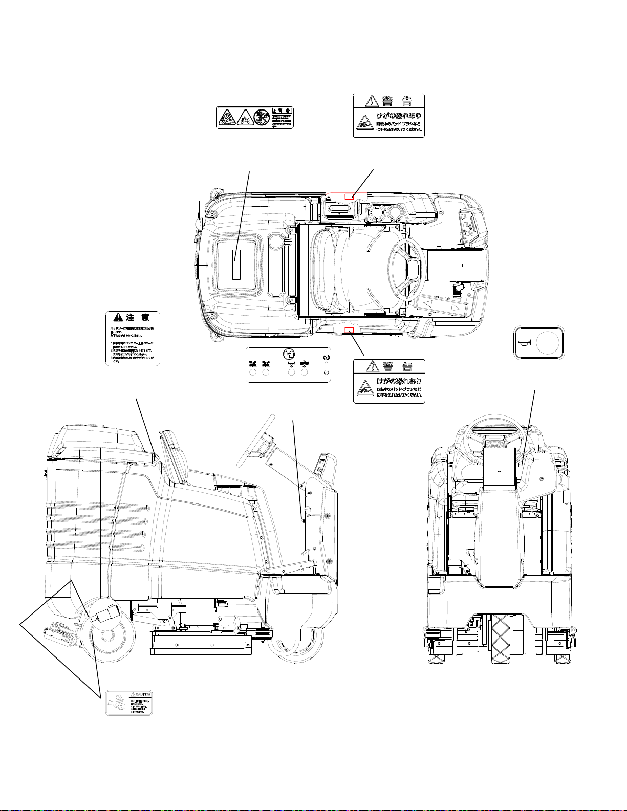
SAFETY LABEL LOCATION
NOTE: These drawings indicate the location of safety labels on the machine. If at any time the labels become
illegible, promptly replace them.
BATTERY CAUTION
86248210
PRV NO. 500109
SAFETY DECAL
86242480
PRV NO. 500111
CIRCUIT BREAKER
86244130
PRV NO. 500859
BRUSH CAUTION
86242510
PRV NO. 500115
HORN DECAL
86248210
PRV NO. 81349
BRUSH CAUTION
86242510
PRV NO. 500115
PINCH POINT WARNING
86243830
PRV NO. 500663 (2)
SGJ32 86037680 01/03/07
2-3
Page 8

TECHNICAL SPECIFICATIONS
ITEM DIMENSION/CAPACITY
Nominal power 2.9 kW
Rated Voltage 36 Volts DC
Rated Amperage 80 amps
Batteries 6 x 6 Volt 250-335 AH @20 hr. rate
Scrub Brush Motors 2 x 1.0 HP (746 W)
Vacuum Motor(s) 1 x .75 HP (560 W) Standard, second motor
optional
Propelling Motor 1.3 HP (932 W)
Mass (GVW) 1810 lbs (820 kg)
Weight empty without batteries 790 lbs (360 kg)
Solution Control Gravity feed, fully variable with automatic
shut off in neutral
Solution tank capacity 30 gal (115 L)
Recovery tank capacity 30 gal (115 L)
Scrub brush diameter for 32 in. (81 cm) disk scrub head 16 inch (40.6 cm)
Scrub brush pressure 0-225 lbs (0-1000N)
Scrub brush speed 300 rpm
Tires 12 in. (30.5 cm) Solid Scrubber Compound
Foundation Pressure 108 lbs./in² (745 kPa)
Maximum Speed 4.1 miles/hour (6.5 Km/hour)
Coverage with 32 in. (81 cm) scrub head 48,840 ft²/hr @ 3.7 mph with 2 in. overlap
Frame Construction Powder coated steel
Brakes Self centering mechanical 7 in. (17.7 cm)
disc with hand lock parking brake
Minimum aisle u-turn width 32 in. (81 cm) disk scrub head 66 inches (168 cm)
Maximum rated climb and descent angle 7.5 degrees
3-1
SGJ32 86037680 01/03/07
Page 9
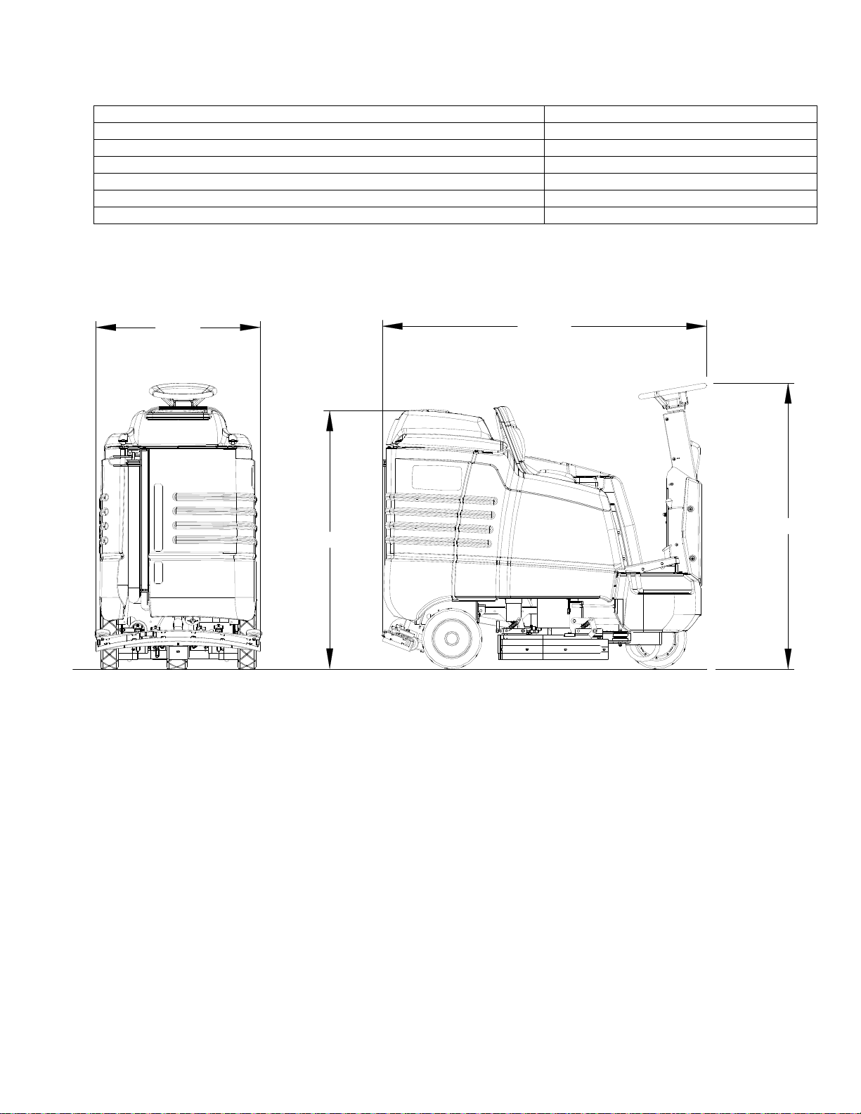
TECHNICAL SPECIFICATIONS
ITEM MEASURE
Height 1 51 inches (130 cm)
Height 2 56.6 inches (144 cm)
Length 63.5 inches (161 cm)
Width without squeegee and scrub head 31 inches (79 cm)
Width of squeegee 33 inches (84 cm)
Width of scrub path for 32 in. (81 cm) 32 inches (81 cm)
WIDTH
LENGTH
HEIGHT 2
HEIGHT 1
SPECIAL NOTES:
The sound pressure level at the operator’s ear was
measured to be 72.3 dBA. This was a nearfield, broadband measurement taken in a typical industrial
environment on a tile floor. This appliance contains no
possible source of impact noise. The instantaneous
sound pressure level is below 63 Pa.
SGJ32 86037680 01/03/07
The weighted root mean square acceleration at the
operator’s arms was measured to be below 2.5m/s
This was a tri-axial, third-octave-band measurement
made during normal operation on a composite tile
floor. The measurement and related calculations were
made in accordance with ANSI S3.34-1986.
2
.
3-2
Page 10

HOW THE MACHINE WORKS
The Saber Glide is a battery powered, selfpropelled, hard floor scrubber intended for
commercial use. The appliance applies a cleaning
solution onto a hard floor, scrubs the floor with
brushes, and then vacuums the soiled water back
into the recovery tank.
The machine's primary systems are the solution
system, scrub system, recovery system, and
operator control system.
The function of the solution system is to store
cleaning solution and deliver it to the scrub system.
The solution system consists of the solution tank,
strainer, valve and controls. The solution tank
stores cleaning solution (water and detergent) until it
is delivered to the scrub system. The strainer
protects the valve from debris. The valve is a
solenoid type valve, which controls the delivery of
cleaning solution to the scrub system. The valve
automatically prevents solution flow unless the scrub
brushes are turned on and the machine is being
propelled. The solution control switch controls the
amount of cleaning solution delivered to the scrub
system by controlling the amount of time the valve is
open.
The function of the scrub system is to scrub the
floor.
The disk scrub systems consists of two rotary type
disk scrub brushes, motors, scrub deck skirt, lift
actuator and controls. The brushes scrub the floor
as the motors drive the brushes. The brush drive
hubs allow the scrub brushes to follow irregularities
and changes in the floor without loosing contact with
the floor. The scrub deck skirts and side squeegees
control the cleaning solution on the floor so that the
squeegee can pick it up. The one touch switch
controls the motors and lift actuator to turn the
motors on and lower the deck, or turn the motors off
and raise the deck. The brush pressure switch
controls the down pressure on the scrub deck.
3-3
SGJ32 86037680 01/03/07
The function of the recovery system is to vacuum the
soiled water back into the recovery tank. The
recovery system consists of the squeegee, vacuum
motor, filter, recovery tank and controls. The
squeegee wipes the dirty solution off the floor as the
machine moves forward. The vacuum motor
provides suction to draw the dirty solution off the
floor and into the recovery tank. The filter protects
the vacuum fan from debris and foam. The recovery
tank stores the dirty solution.
The float switch in the tank activates the recovery
tank full indicator, shuts off the scrub motors and
solution flow, raises the scrub deck then squeegee,
and shuts off vacuum motor.
The function of the operator control system is to
control the direction and speed of the machine. The
directional control system consists of the
direction/speed control pedal, steering wheel, brake
pedal, propel controller, and drive wheel. The
direction/speed pedal signals forward or reverse
direction and speed. The controller interprets signals
from the direction/speed pedal to command the drive
wheel to propel or slow the machine. The steering
wheel points the drive wheel in the direction desired
by the operator. The brake can be used to hold the
machine on slopes.
Page 11
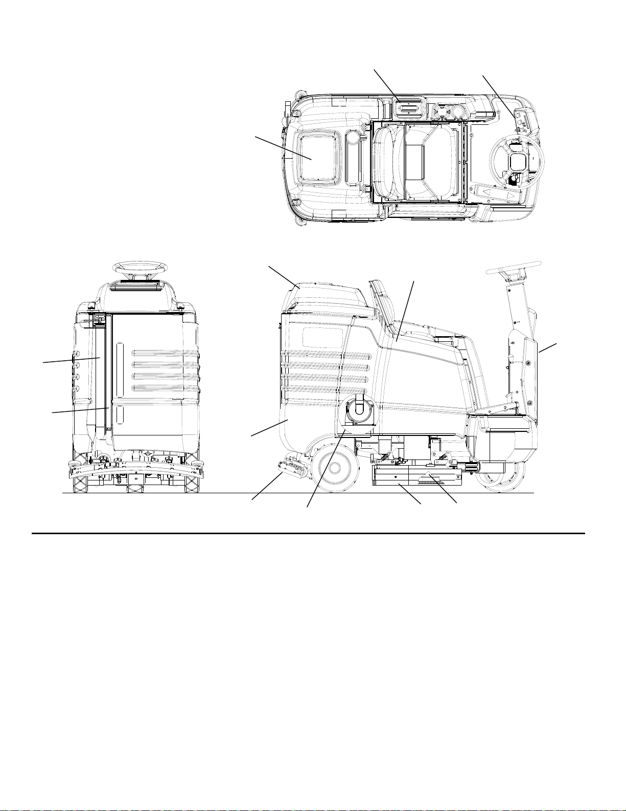
COMPONENTS
6
5
11
1
3
2
7
10
1. Control panel
2. Front cover
3. Side cover
4. Tank
5. Recovery tank cover
6. Recovery tank dome
7. Recovery tank drain hose
4
12
13
9
8. Scrub head
9. Scrub head side squeegee
10. Solution tank drain hose
11. Solution tank cover
12. Squeegee
13. Vacuum motor
8
SGJ32 86037680 01/03/07
3-4
Page 12
CONTROLS
3
7
5
6
4
18
19
8
10
20
1
2
17
16
14
15
12
3-5
20
SGJ32 86037680 01/03/07
13
11
9
Page 13
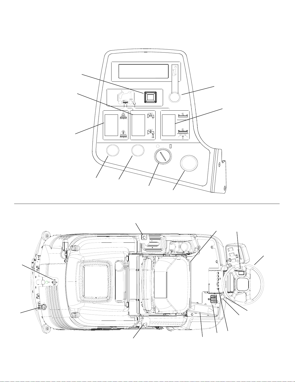
CONTROLS
1. Key switch
2. Emergency stop button
3. One touch switch
4. Brush pressure switch
5. Solution control switch
6. Vacuum/squeegee switch
7. Display toggle switch
• Information Screen 1
• Information Screen 2
• Hour meter
• Fault codes and special icons
• Battery meter
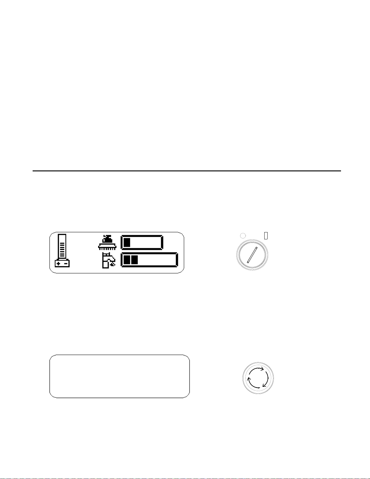
1. KEY SWITCH
Controls the power for the machine functions. To turn the machine power on, rotate key clockwise. When the
key is turned on the battery symbol will flash for 12 seconds while the system runs self-diagnostics and
returns scrub deck and squeegee to raised position, if necessary. The controller will not respond to other
commands until this routine is complete. To turn the machine power off, rotate key counterclockwise.
8. Recycle switch (optional)
9. Recycle indicator light (optional)
10. Headlight switch (optional)
11. Brake pedal
12. Parking brake lever
13. Directional control pedal and speed
reduction feature.
14. Steering wheel
15. Steering tilt lever
16. Horn button
17. Seat adjustment grab bar
18. Squeegee camber adjustment knob
19. Squeegee deflection adjustment knob
20. Side squeegee deflection adjustment knob
INFORMATION DISPLAY
2. EMERGENCY STOP BUTTON
This safety feature is designed to cut all power to the machine at any time. To shut the machine power off,
push the Emergency Stop switch. To reset the machine, rotate the switch clockwise.
INFORMATION DISPLAY
SGJ32 86037680 01/03/07
3-6
Page 14

CONTROLS
3. ONE TOUCH SWITCH
This switch controls the scrub brushes and vacuum all in one touch.
To start scrubbing, press the one touch switch. The brush drive motors will turn on, the scrub deck will lower
to the "light scrub" position, the solution will flow at “two bars” rate, the squeegee will lower and the vacuum
will turn on. The information display window will show which functions are operating. If the direction control
pedal is in the neutral position for more than two seconds the brushes and solution flow will stop. If the one
touch switch is activated without brushes installed, the brush motors will stop, the scrub deck will rise, and the
brush pressure indicator will display error code 9000. To stop scrubbing, press the one touch switch. The
brush drive motors will turn off, the scrub deck will raise the solution flow will stop, the squeegee will raise
after a 15 second delay, and the vacuum motor will turn off. This delay is to clear the vacuum hose of
recovered solution.
4. BRUSH PRESSURE SWITCH
This switch controls the amount of brush pressure to the floor. There are 5 different pressure settings. To
decrease the amount of down pressure, press the top of the brush pressure switch (-). To increase the
amount of down pressure, press the bottom of the brush pressure switch (+). The information display screen
will show the amount of pressure.
NOTE: Press switch and hold momentarily each time to change brush pressure.
INFORMATION DISPLAY
INFORMATION DISPLAY
LESS PRESSURE
MORE PRESSURE
3-7
SGJ32 86037680 01/03/07
Page 15

CONTROLS
5. SOLUTION CONTROL SWITCH
This switch controls the amount of solution flow to the scrub deck. There are 7 different flow settings. To
increase the solution flow, press the solution control switch (+). To decrease solution flow, press the top of
the switch (-). If the brush motors are turned off or the direction control pedal is in neutral, the flow is
automatically interrupted until the motors are turned on again, or the drive pedal is moved forward or reverse.
This feature prevents unintentional draining of the solution tank and allows the operator to adjust the solution
flow to the scrub deck without resetting each time the scrubbing operation is interrupted. If recycling option is
installed, this switch controls the amount of solution flow to the scrub deck by controlling the speed of the
pump.
NOTE: Press switch and hold momentarily each time to change solution flow.
6. VACUUM/SQUEEGEE SWITCH
LESS SOLUTION
This switch independently controls the vacuum motor and squeegee position. To start the vacuum motor a nd
lower the squeegee to the floor, press the bottom of the switch. To raise the squeegee and turn off the
vacuum motor, press the top of the switch. The squeegee will raise after a 15 second delay, and the vacuum
motor will turn off 15 seconds later, in order to clear vacuum hose of recovered solution.
INFORMATION DISPLAY
MORE SOLUTION
INFORMATION DISPLAY
Indicates vac motor is running
SGJ32 86037680 01/03/07
3-8
Page 16

CONTROLS
7. DISPLAY TOGGLE SWITCH
The display toggle switch allows you to change the information display screen. Two screens are
available.
• INFORMATION DISPLAY –SCREEN 1
• INFORMATION DISPLAY –SCREEN 2
• The hour meter is viewed on screen 2 of the information display. Hours are displayed for key ON
time, brush run time, and traction motor time.
Key ON Hours:
Records the entire time that the key is on.
Brush Run Time:
Records the time spent with the brushes running and
gives true brush motor time.
Traction Motor Time:
• Fault codes/icon will appear on either display screen when the controller detects a problem within the electrical
system. The codes/icons are used to assist users as well as service technicians in identifying and correcting
problems. See troubleshooting section for more information on fault codes.
• Icon appears if throttle is depressed when the key is turned on. To correct, lift foot off of throttle. If this does
not clear the icon, the throttle may be damaged and should be checked by a qualified service technician.
Records the time spent propelling the machine and gives
true traction motor time.
3-9
SGJ32 86037680 01/03/07
Page 17

CONTROLS
• The float switch is located inside the recovery tank. The purpose of the float switch is to notify the user that
the recovery tank is full. When the float switch is activated, the scrub brush motors and solution flow will stop,
the scrub deck will raise, the squeegee will rise after 60 seconds, and the vacuum motor will turn off 10
seconds later.
• The battery meter can be viewed at the left side of either information screen 1 or information screen 2. The
level of battery charge is indicated by the horizontal bars in the battery meter box. When the batteries require
charging, the icon will flash and a battery inhibit icon will appear on the right side of either information screen.
Scrub and solution functions that are running when the battery inhibit icon appears will be automatically sh ut
off. It is not possible to restart scrub functions while the battery inhibit is displayed. The controller reserves
enough battery charge to allow pick-up of residual water and transport back to a charging station.
SGJ32 86037680 01/03/07
3-10
Page 18

CONTROLS
8. RECYCLE SWITCH (OPTIONAL)
This switch controls the solution recycle pump. To start recycle pump, press the switch. A green light
above the circuit breakers will indicate that pump is on. The solution control switch will control the
speed of the pump and therefore the amount of solution flow to the scrub deck. Make sure there is an
adequate amount of water in recovery tank before starting recycle pump, and turn off recycle pump
when water level reaches filter. To stop the solution recycle pump, press the switch. The pump will
stop and the green indicator light will turn off, and the solenoid valve will resume control of solution
flow to the scrub deck.
9. RECYCLE INDICATOR LIGHT (OPTIONAL)
This light will turn on when the recycle pump is on, and turn off when the recycle pump is off.
10. HEADLIGHT SWITCH (OPTIONAL)
Turns on optional headlight for improved visibility in low light areas.
3-11
SGJ32 86037680 01/03/07
Page 19

CONTROLS
11. BRAKE PEDAL
The brake pedal is located on the floor to the right side of the steering column pedestal. The pedal operates
the disc brake on the drive wheel. To slow or stop the vehicle, apply pressure to the brake pedal.
12. PARKING BRAKE LEVER
The black knob located on the right side of the steering column pedestal is used to set the parking brake. To
set the parking brake, fully depress the brake pedal and push the parking brake knob. To release the parking
brake, fully depress the brake pedal. Then release pressure on the brake pedal. The parking brake kn ob will
return it to its’ released position.
FOR SAFETY: Before leaving or servicing machine; stop on level surface, set parking brake, turn off
machine and remove key.
13. DIRECTIONAL CONTROL PEDAL AND SPEED REDUCTION FEATURE
This pedal controls the direction of travel and the speed of the vehicle. Slowly pressing the front of the pedal
causes the machine to travel forward. Pressing the rear of the pedal causes the vehicle to travel in reverse.
The vehicle speed can be controlled by varying the pressure on the front or rear of the pedal.
FOR SAFETY: The vehicle can coast for a short distance after releasing the directional pedal.
Remove the foot from pedal and use brakes to slow or stop the machine.
SPEED REDUCTION FEATURE
Maximum speed of machine can be decreased to 80% of maximum by disconnecting wire 3 white from wire 16
white, located between controller and LCD display. Machine is set at 100% speed setting at factory.
REVERSE
FORWARD
SGJ32 86037680 01/03/07
3-12
Page 20

CONTROLS
14. STEERING WHEEL
The steering wheel turns the front wheel causing the machine to change direction.
15. STEERING TILT LEVER
The steering tilt lever is located on the right side of the steering wheel. To engage the tilt adjustment,
pull on the lever and adjust the steering column to desired position. Release lever and allow it to lock
into desired position.
16. HORN BUTTON
The horn button is located on left side of the steering column. The horn is activated by pressing the
horn button.
17. SEAT ADJUSTMENT GRAB BAR
The seat adjustment grab bar is located in front of seat at the bottom. While in a standing position,
grasp the back of the seat and the seat adjustment grab bar and lift seat into the adjustment slot and
lower into one of the locking positions. Adjust the seat to the desired position.
Locking position
Adjustment slot
18. SQUEEGEE CAMBER ADJUSTMENT KNOB
The squeegee camber adjustment knob is located at the center of the squeegee at the rear of the
machine. (See maintenance section for adjustment).
19. SQUEEGEE DEFECTION ADJUSTMENT KNOB
The squeegee deflection knob is located at the rear of the machine, on the right side of the squeegee
assembly. (See maintenance section for adjustment).
20. SIDE SQUEEGEE DEFECTION ADJUSTMENT KNOB
Side squeegee adjustment knobs are located above the scrub deck. (See maintenance section for
adjustment).
3-13
SGJ32 86037680 01/03/07
Page 21

PRE-RUN MACHINE INSPECTION
1. Do a pre-run inspection to find possible
problems that could cause poor performance or
lost time from breakdown. Follow the same
procedure each time to avoid missing steps.
Visually check for exterior damage, leaks,
damaged or worn tires.
2. Check brushes or pads an d drivers for proper
installation and wear. Weekly check scrub deck
skirts for proper contact with floor. See
BRUSHES in MAINTENANCE SECTION.
3. Check squeegee for wear and proper
adjustment. See SQUEEGEE ADJUSTMENT in
MAINTENANCE SECTION.
4. Check for securely attached drain hose, plug,
and caps.
5. Check battery condition, recharge if necessary.
See BATTERIES in maintenance section.
6. Check the brakes and steering for pro per
operation. See BRAKES and STEERING in
MAINTENANCE SECTION.
STARTING MACHINE
NOTE: Perform pre-run machine check before
operating machine.
FOR SAFETY: Before starting machine, make
sure that all safety devices are in place and
operating properly.
1. The operator should be in the seat with the right
foot on the brake pedal or with the parking brake
on. The directional pedal must be in the neutral
position to avoid unintentional movement.
NOTE: The Operator must be in position on the
seat to activate machine in desired direction.
2. Turn the key switch clockwise to the “ON”
position.
3. Release the brake, then press lightly on the
directional pedal in the desired direction and
drive to the filling area.
FILLING THE MACHINE
FOR SAFETY: Before leaving or servicing
machine; stop on level surface, set parking
brake, turn off machine and remove key.
1. Set squeegee and scrub deck to up position, set
parking brake, and turn off key switch.
2. Remove solution tank cover.
! WARNING
Do not use flammable materials in the tanks.
Flammable materials can
cause an explosion or fire.
SGJ32 86037680 01/03/07
MACHINE OPERATION
The solution tank can be filled to the FULL
3.
marking of the fill inlet. Leave room for
detergent. The solution tank capacity is 30
gallons (114 liters).
The water must not be hotter than 140' (60'C) to
prevent damage to the tank. Measure the
required amount of chemical into the solution
tank after filling with water. Dry chemicals
should be thoroughly mixed before being added
into solution tank. Commercially available, high
alkaline floor cleaners are suitable for use in the
solution system.
4. Inspect solution tank cover vent for obstructions.
Replace solution tank cover.
SCRUBBING
Plan the scrubbing pattern in advance. The longest
track is around the perimeter of the area to be
cleaned. For efficient operation, the runs should be
the longest possible without turning, stopping, or
raising or lowering scrub deck/squeegee.
In order to achieve the best possible results, the
area which is to be cleaned should be swept before
scrubbing. Large debris, strings and wire must be
removed to prevent being caught in brushes or
squeegee.
The machine will automatically raise the squeegee
slightly when reverse travel is selected. If the
machine is allowed to stand in neutral with the scrub
deck down for more than 2 seconds, the solutions
flow stops and brush motors stop. If either forward
or reverse travel is selected, the solution flow will
continue in the same setting and the scrub brush
motors will continue in their same setting once
movement of machine begins. Overlap the brush
path and avoid transporting over previously cleaned
areas.
3-14
Page 22

MACHINE OPERATION
TO BEGIN SCRUBBING
! CAUTION
pay close attention for unexpected movement.
Use extra caution around children.
1. Place right foot on brake pedal or check to make
sure parking brake has been set.
2. With directional pedal in neutral turn key switch
to “ON”.
3. Release brake.
4. Press the directional pedal to travel in the
desired direction and steer to the start of the
scrub pattern.
5. Press the one-touch switch (#1) on the control
panel. The brush motors will start, the scrub
deck will lower to the light scrub position, the
solution will begin to flow, the squeegee will
lower to the floor and the vacuum motors will
start.
6. Adjust the speed of the machine, solution flow
and scrub brush pressure as necessary.
NOTE: Once solution flow rate is set it is not
necessary to shut off solution when stopping
scrubbing. Solution flow is automatically shut off
when brush motors stop. When brush motors
are activated, flow automatically resumes.
! WARNING
explosions or fire! Do not pick up.
TO STOP SCRUBBING
1. Press the one-touch switch (#1) on the control
panel. The brush motors will stop and the scrub
deck will raise to the park position. After 15
seconds, the squeegee will raise, and 15
seconds later the vacuum motor will turn off.
This delay is to clear the vacuum hose of
recovered solution.
2. Allow directional pedal to return to neutral.
3. Apply brake to stop machine.
4. Turn key switch off.
5. Set parking brake.
FOR SAFETY: Before leaving or servicing
machine; stop on level surface, set parking
brake, turn off machine and remove key.
When operating the
machine around people,
Flammable liquids and/or
reactive metals can cause
EMERGENCY STOP PROCEDURE
1. Turn key switch to off position. If an electrical
problem is suspected push in emergency stop
button.
2. Release pressure on directional pedal.
3. Apply brakes.
NOTE: Turning the key switch off during normal
running operation will stop all motors and actuators.
When the key is turned back on the system will
automatically return scrub deck and squeegee to
raised position.
DOUBLE SCRUB
Floors which are heavily soiled or have thick
accumulation of floor finish may not clean sufficiently
with one pass. In these cases it will be necessary to
double scrub.
To double scrub, make the first pass over the
surface being cleaned with the squeegee up, the
solution on, and brushes down. This allows the
solution to stay in contract with the soil while
loosening the surface accumulation with the
brushes. Allow time for the first application to stay in
contact with floor. Length of time between the first
and second pass depends on amount of
accumulation and the type of chemical being used.
A second scrubbing with the squeegee down and
again the solution and brushes on will further loosen
soil. The additional application of solution will further
assist the difficult cleaning job. Caution should be
used when double scrubbing, maintain safe driving
speed on wet floors.
3-15
SGJ32 86037680 01/03/07
Page 23

EMPTYING AND CLEANING TANKS
RECOVERY TANK
1. Touch the one-touch switch (#1) on the control
panel to raise the scrub deck, stop the motors,
and solution flow, raise the squeegee and turn
off vacuum motors.
2. Park the machine next to a floor drain. Drain
hose is on left rear corner of machine.
3. Turn off the key switch and set the machine’s
parking brake.
4. Unhook the drain hose from retainer. Unscrew
T-handle on plug enough to loosen plug and
lower hose in direction of drain. Stand behind
end of hose. Recovered solution will come out
with force. Slowly remove plug from drain hose.
5. Remove recovery tank dome.
6. Flush the recovery tank out with clean water.
Repeat until clean water comes out of drain
hose. Do not use water hotter than 140' (60'C)
to clean the tank. Damage to tank may occur.
7. Replace plug and secure drain hose in bracket.
8. If machine is to be stored, leave recovery tank
dome open and drain hose plug off.
RECOVERY
DRAIN HOSE
REAR VIEW
SOLUTION
DRAIN HOSE
MACHINE OPERATION
SOLUTION TANK
1. Park the machine next to a floor drain. Drain
hose is on left rear adjacent to recovery tank
drain hose.
2. Turn off the key switch and set the machine’s
parking brake.
3. Unhook the small drain hose from the retainer.
Lower hose in direction of the drain.
4. Remove the solution tank cover.
5. Flush the solution tank out with clean water and
run several gallons of clean water through
systems. Do not use water hotter than 140º F
(60º C) to clean tank. Damage may occur.
NOTE: Never allow solution to remain in tank.
Damage to tank, seals and valves could occur.
6. Secure drain hose in bracket.
RECOVERY
TANK DOME
TOP VIEW
SOLUTION
TANK COVER
SGJ32 86037680 01/03/07
3-16
Page 24

MAINTENANCE
10
7
5
2
6
13
1
14
15
1. Batteries
2. Squeegee Adjustment
3. Side Squeegee Adjustment
4. Scrub Brushes
5. Vacuum Filter
6. Float Switch
7. Solution Strainer
8. Brake
16
3
11
4
9. Steering Chain Tensioner
10. Vacuum Motor
11. Brush Motor
12. Traction Motor
13. Fuse
14. Circuit Breaker
15. Squeegee Lift Actuator
16. Scrub Lift Actuator
12
8
9
4-1
SGJ32 86037680 01/03/07
Page 25

2
1. BATTERIES
The batteries provide the power to operate the
machine. The batteries require regular maintenance
to keep them operating at peak efficiency.
To get the greatest life from the batteries charge
them when their charge level reaches 25%of a full
charge. Use a hydrometer to check the charge
level.
Do not allow the batteries to remain in a discharged
condition for any length of time. Never expose a
discharged battery to temperatures below freezing.
Discharged batteries will freeze causing cracked
case. Do not operate the machine if the batteries
are in poor condition or if they have a charge level
below 25%, specific gravity below 1.177.
Keep all metallic objects off the top of the batteries,
as they may cause a short circuit. Replace worn or
damaged cables and terminals.
Check the electrolyte level in each battery cell
before and after charging the batteries. Never add
acid to the batteries, use water. Do not allow water
level to fall below the battery plates. Portions of
plates exposed to air will be destroyed. Do not
overfill. Keep plugs firmly in place at all times.
! WARNING
! WARNING
Keep sparks and open flame away. Keep covers
open when charging.
! WARNING
working with batteries.
! WARNING
When servicing machine,
avoid contact with acid.
Batteries emit hydrogen gas.
Explosion or fire can result.
Wear eye protection and
protective clothing when
Charge batteries in a well
ventilated area.
BATTERY MAINTENANCE
1. When cleaning the batteries, use a solution of
baking soda and water. Do not allow the
cleaning fluid to enter the battery cells.
Electrolyte will be neutralized.
2. Maintain the proper electrolyte level in each
battery cell. If a cell should accidentally
overflow, clean immediately.
3. Do not add water until the battery is fully
charged.
4. Wipe off the top of the batteries at least once a
week.
5. Test battery condition with a hydrometer at least
once a week.
MAINTENANCE
6. Ensure that all connections are tight and all
corrosion removed.
7. Every 4 to 6 months, remove the batteries from
the machine and clean the battery cases and
battery compartment.
NOTE: Do not take readings immediately after
adding water. If the water and acid are not
thoroughly mixed, the reading may not be accurate.
To find the correct specific gravity reading when the
temperature of the battery electrolyte is other then
80' F (27' C).
SPECIFIC GRAVITY BATTERY CONDITION
1.265 100% CHARGED
1.225 75% CHARGED
1.190 50% CHARGED
1.155 25% CHARGED
1.120 DISCHARGED
Add (+) to the specific gravity reading
0.004 (4 points), for each 10' F (6' C) above 80' F
(27' C) Subtract (-) from the specific gravity reading
0.004 (4 points), for each 10' F (6' C) below 80' F
(27' C).
SGJ32 86037680 01/03/07
4-
Page 26

MAINTENANCE
TO CHARGE BATTERIES
When servicing machine, avoid contact with
! WARNING
Batteries emit hydrogen gas. Explosion or fire
! WARNING
Keep covers open when charging.
Wear eye protection and protective clothing
! WARNING
Charge batteries in a well ventilated area.
! WARNING
clean, well ventilated area next to the charger.
2. Turn the machine off and set parking brake.
FOR SAFETY: Before leaving or servicing
machine, stop on level surface, apply parking
brake, turn off machine and remove key.
3. Raise the seat and raise the support arm to lock
in place.
Batteries emit hydrogen gas. Explosion or fire
can result. Keep sparks and open flame away.
! WARNING
4. Check the electrolyte level in each battery cell.
Before charging, add just enough water to cover
up the plates. After recharging has completed,
add just enough water to bring up the level to
the indicator ring. If water level is to high before
charging, normal expansion of the electrolytes
may cause and overflow, resulting in loss of
battery acid balance and damage to the
machine.
5. Replace battery caps, and leave them in place
while charging.
6. Unplug the battery connector from the machine.
Unplug the battery charger from power outlet.
FOR SAFETY: When charging, connect the
charger to the batteries before connecting the
charger to the AC wall outlet. Never connect the
charger to the AC first. Hazardous sparks may
result.
7. Use a 36 volt DC charger which will
automatically shut off when the batteries are
fully charged to charge the six battery pack.
acid.
can result. Keep sparks
and open flame away.
whe n working with
batteries.
1. Stop the machine in a
Keep covers open when
charging.
8. Plug the charger into the battery connector. Plug
battery charger into power outlet. The charger
gauge should indicate that the batteries are
charging. If the charger does not automatically
start up, verify that charger is plugged into
batteries.
9. When the batteries are fully charged, disconnect
the charger from the batteries.
10. Connect the batteries to the machine connector.
11. Check the electrolyte level. It should be up to
the indicator ring. If necessary, add distilled
water.
12. Lower the seat.
LOW BATTERY SHUT-DOWN
The electronic system is equipped with battery
voltage sensors. When the batteries are exhausted
to a preset level, the scrubbing system will shut
down to protect the batteries from damage, and the
battery lockout icon will appear on the display.
4-3
SGJ32 86037680 01/03/07
Page 27

TO REMOVE BATTERIES
1. Stop the machine in a clean area next to the
charger.
2. Turn off machine and set parking brake.
FOR SAFETY: Before leaving or servicing
machine, stop on level surface, apply parking
brake, turn off machine and remove key.
3. Raise the seat plate.
4. Remove side cover.
5. Disconnect battery pack from the machine.
6. Use the proper size open end wrench to
disconnect main ground wire first and secure
cable terminal away from batteries.
7. Disconnect main positive lead and secure cable
terminal away from battery/batteries.
8. Loosen both terminals on each jumper cable
and remove one at a time.
9. Prepare a suitable battery site to place batteries.
10. Attach suitable battery lifting device and lift
batteries from the machine.
! CAUTION
Batteries are a potential environmental hazard.
Consult your battery supplier for safe disposal
methods.
MAINTENANCE
TO REPLACE BATTERIES
1. Refer to diagram. Place batteries in battery
compartment.
2. Connect all jumper cables positive to negative to
the six batteries.
3. Connect the positive cable to battery in the
position shown.
4. Connect negative cable to battery in the position
shown.
CHARGER CONNECTION
SGJ32 86037680 01/03/07
4-4
Page 28

MAINTENANCE
2. SQUEEGEE ADJUSTMENT
Adjusting the squeegee is a two-part process. First,
the squeegee tool must have correct pitch in order
for the squeegee blade to have the same deflection
at each tip as well as the center. The pitch
adjustment is facilitated by the use of a spirit level
mounted on the squeegee tool. The second
adjustment is the amount of deflection or down
pressure on the squeegee.
TO ADJUST SQUEEGEE PITCH
1. Choose a smooth, level surface. Turn on the key
switch, release the machine parking brake,
lower the squeegee and drive forward at least 2
feet (60 cm).
2. With the squeegee down, stop the machine and
set the parking brake. Do not allow the machine
to roll back.
FOR SAFETY: Before leaving or servicing
machine; stop on level surface, turn off machine
and remove key.
3. Determine the differences, if any, in deflection of
the squeegee blade between each end and the
middle. Proper adjustment is obtained when
deflection is equal all the way across tool. This
should correspond to the bubble being in the
middle position of the spirit level.
4. To decrease the deflection of the squeegee
blade at the ends, turn knob on squeegee
trailing arm clockwise. To increase the deflection
at the ends of the squeegee assembly, turn
knob counter clockwise.
5. Again check the deflection of the squeegee
blades. Repeat steps 1 through 4 until the
deflection is equal across the entire rear
squeegee blade.
TO ADJUST SQUEEGEE DEFLECTION
3/8”
PROPER DEFLECTION OF SQUEEGEE BLADE
1. Choose a smooth, level surface. Lower the
squeegee and drive forward at least 2 feet.
2. With the squeegee down, stop the machine and
set the parking brake. Do not allow the machine
to roll back.
FOR SAFETY: Before leaving or servicing
machine; stop on level surface, turn off machine
and remove key.
3. Observe the amount of squeegee deflection. It
should deflect 3/8in (9.5 mm) across the entire
width of the squeegee.
4. To adjust the squeegee deflection, loosen knob
on the squeegee slide bar.
5. Sliding bar to left increases deflection. Sliding
bar to right decreases deflection.
6. Tighten knob on squeegee slide bar.
7. Turn on the key switch, release the machine
parking brake. Raise, then lower squeegee
assembly by pressing the vacuum switch. Drive
forward at least 2 feet.
8. Repeat steps 2 through 7 until defection of
3/8 in. (9.5 mm) is reached.
4-5
SGJ32 86037680 01/03/07
Page 29

MAINTENANCE
6
TO REPLACE OR ROTATE REAR
SQUEEGEE BLADES
1. With the squeegee in the up position, turn off the
key switch and set the parking brake.
FOR SAFETY: Before leaving or servicing
machine; stop on level surface, turn off machine
and remove key.
2. Unlock and pull open latch on rear of squeegee
tool.
3. Remove blade retainer straps from squeegee
tool.
4. Remove squeegee blade from locating pins on
squeegee tool and rotate to new position or
replace as required.
5. nstall blade on locating pins of squeegee tool.
6. Install squeegee retainer straps.
7. Fasten and lock latch. Latch is adjustable.
Adjust latch only tight enough to take up slack in
retaining strap.
NOTE: Changing of squeegee blades does not
always necessitate a readjustment. Refer to section
on adjusting squeegee.
TO REMOVE SQUEEGEE ASSEMBLY
1. With the squeegee in the up position, turn off the
key switch and set the parking brake.
FOR SAFETY: Before leaving or servicing
machine; stop on level surface, turn off machine
and remove key.
2. Disconnect vacuum hose and loosen the two
squeegee retaining knobs.
3. Pull squeegee assembly rearward from the
lifting carrier.
4. With squeegee assembly on bench inspect or
repair as necessary.
5. To reinstall, align squeegee assembly to lift
carrier. Push forward until squeegee is fully
engaged.
6. Tighten knobs.
7. Attach vacuum hose.
TO REPLACE OR ROTATE FRONT
SQUEEGEE BLADES
1. With squeegee assembly on bench, loosen
retaining bolt and locking nut on the left side of
the retaining strap.
2. Remove front retainer strap.
3. Remove squeegee blade from locating pins on
squeegee tool and rotate to new position or
replace as required.
4. Install blade on locating pins of squeegee tool.
5. Replace front retainer strap.
6. Secure strap by tightening retaining bolt and
locking nut on retainer strap.
NOTE: Changing of squeegee blades does not
always necessitate a readjustment. Refer to section
on adjusting squeegee.
SGJ32 86037680 01/03/07
4-
Page 30

MAINTENANCE
3. SIDE SQUEEGEE ADJUSTMENT
TO REPLACE OR ROTATE SIDE SQUEEGEE
BLADES
1. Loosen the locking knob and pivot the side
squeegee out as if to expose the brush.
2. Loosen and remove the three nuts and bolts
securing squeegee blades.
3. Remove the retaining strap and squeegee blade
and rotate or replace squeegee blade.
4. Install blade and retaining strap on locating pin
and reinstall three bolts and nuts.
5. Tighten nuts. Do not over tighten nuts as this
will damage the retaining strap and deform the
squeegee blade.
6. Pivot the side squeegee back into place and
tighten the locking knob.
ADJUSTING THE SIDE SQUEEGEE
DEFLECTION
Side squeegee should deflect approximately 3/8
in. when in use. If the blade is under curled it will
skip low spots and leave puddles. It the blade is
over curled or worn it will smear water and leave
stripes and streaks.
1. Choose a smooth level surface. Lower the
scrub deck to the floor and drive forward slowly
while observing the curl and squeegee
performance.
2. To increase the curl, turn the deflection
adjustment knob counter clockwise.
3. To decrease the curl, turn the deflection
adjustment knob clockwise.
4-7
SGJ32 86037680 01/03/07
Page 31

4. SCRUB BRUSHES
There are five different types of brushes available to
cover applications from cleaning heavily soiled floors
to polishing. A pad driver is also available to take
advantage of the many cleaning pads on the market
and further add to the flexibility of the machine.
Please refer to the following to assist in selecting the
proper brush or pad for the work at hand.
UNCOATED FLOORS
Aggressive Grit is a nylon fiber impregnated with
silicone carbide grit. It grinds away stain, soil, and
removes surface material.
Mild Grit is a less aggressive silicone carbide grit
suitable for cleaning medium soil conditions.
Advantages are faster ground speed than nylon
bristles on light solid applications.
Nylon is a general-purpose scrub brush with stiff
bristles.
Polypropylene works well for maintaining concrete,
wood and tile floors.
FINISHED FLOORS
Nylon bristles are used in a variety of applications
on coated or uncoated surfaces.
Polypropylene bristles work on a variety of floor
surfaces. Does not soften in water
White Pads (Polishing) are used for dry polishing to
achieve a high-gloss appearance, or surface
washing on highly polished or burnished floors.
Red Pads (Buffing) are used for light-duty
scrubbing. When used with a mild detergent they
will provide surface cleaning without removing the
finish.
Blue Pads (Scrubbing) are used for heavy-duty
scrubbing and light stripping. The blue pads remove
less finish than brown stripping pads, yet will remove
black marks, stains and dirt.
Brown Pads (Stripping) are used for easy and
complete removal of old floor waxes/finishes. They
will quickly remove ground in dirt, black heel marks,
and spills. When used with the proper stripper, this
pad leaves the floor clean and ready for finishing.
MAINTENANCE
REPLACING OR INSTALLING SCRUB
BRUSHES
The scrub brushes should be checked before each
days work for wire, string, wear, or damage. The
scrub brushes should be replaced if brush bristles
are missing or if shorter than 5/8 inch.
NOTE: For uniform scrubbing, scrub brushes must
be replaced as a set.
1. With the scrub deck up, turn off the machine and
set the parking brake.
2. Loosen side squeegee locking knob, and pivot
side squeegee away from scrub deck.
3. Locate release lever on top of brush or pad
driver. With finger rotate release lever against
spring pressure counter clockwise. Brush/pad
driver will release and drop down.
4. To reinstall, center the cut out of the release
lever plate on brush/pad driver to be installed
under the brush drive hub.
5. Raise brush/pad drive up until assembly
contacts brush hub. Rotate slightly until drive
engages release lever plate.
6. While holding upward pressure, rotate brush/pad
driver assembly clockwise. When fully engaged,
release lever plate will rotate under spring
pressure to lock assembly.
NOTE: Check that release plate is completely closed
and pad/brush is securely attached. Damage to
driver or brush could occur.
7. Repeat the procedure for the opposite side of
the machine.
SGJ32 86037680 01/03/07
4-8
Page 32

MAINTENANCE
5. VACUUM FILTER
The vacuum filter is located inside the recovery tank.
The vacuum filter prevents debris from entering the
vacuum motor. Daily remove and clean filter of any
debris for maximum airflow.
6. FLOAT SWITCH
The float switch is located inside the recovery tank.
The purpose of the float switch is to notify the user
that the recovery tank is full. When the float switch is
activated, the scrub brush motors and solution flow
will stop, the scrub deck will raise, the squeegee will
rise after 60 seconds, and the vacuum motor will
turn off 10 seconds later.
Icon appears on information screen 1 when
7. SOLUTION STRAI NER
The solution strainer is located behind the right rear
wheel of the Glide. The solution strainer protects the
solenoid valve from debris. If there is little or no
solution flow to the ground, check the strainer for
debris. Drain the solution tank and clean the solution
strainer. To remove the strainer, turn the bottom part
of the strainer counterclockwise until the bottom is
separated. Clean out the debris from the wire mesh
and re-assemble. Make sure the O-ring gasket is in
place when re-assembled.
8. BRAKE
(Refer to Brake Group in the Parts section of the
manual).
The brake pedal and parking brake operate the selfcentering front wheel disc brake. The disc and
caliper should be inspected every 200hours of
operation for cracks and disc wear. The brake
should be adjusted so that the disc pads are as
close to the disc as possible, without causing brakes
to drag.
float switch is activated.
BRAKE ADJUSTMENT
FOR SAFETY: Before leaving or servicing machine,
stop on a level surface, turn off machine and remove
key.
1. Disconnect batteries from machine.
2. Turn the steering wheel fully to the left.
3. Locate the brake adjustment screw on the brake
caliper.
4. Loosen the lock nut.
5. Turn adjustment screw in until finger tight, then
back off 1/8 turn.
6. Hold adjustment screw and tighten lock nut.
9. STEERING CHAIN TENSIONER
(Refer to Steering Group in parts section of manual).
The steering chain transfers power from the steering
shaft to the drive wheel, controlling steering
response. Check the chain condition and tension
every 200 hours of operation. Proper chain tension
is important to maintain steering response. The
chain should deflect 1/16 in. Use a light spray lube if
needed.
STEERING CHAIN TENSIONER ADJUSTMENT
1. Locate chain tensioner bolts.
2. To increase tension, tighten lock nuts retaining
chain tension plate.
3. To decrease tension, loosen lock nuts retaining
chain tension plate.
4-9
SGJ32 86037680 01/03/07
Page 33

MAINTENANCE
0
10. VACUUM MOTOR
(Refer to the Vacuum Group in the parts section
of manual)
! WARNING
Do not use a pressure washer to clean around
the vacuum motors. Use tap pressure only. Care
must be taken so that water is not directed into
vacuum motor air intakes.
CHANGING VACUUM MOTOR
1. Remove side cover.
2. Disconnect electrical connector to the vacuum
motor.
3. Loosen clamp and disconnect hose from
vacuum intake.
4. Loosen clamp and disconnect vacuum muffler
from vacuum outlet.
5. Remove vacuum motor mounting bracket bolts,
which are located under frame.
6. Remove vacuum motor from mounting bracket
assembly.
7. Reverse steps to install.
Vacuum Motor Carbon Brushes Replacement (Windsor)
End Cap
Vacuum Motor Carbon Brushes Replacement (Ametek)
End Cap
Carbon
Brushes
If armature commutator is grooved, extremely pitted or not
concentric, the motor will need to be replaced or sent to a
qualified service center.
Note:
Place
stop in
groove.
Carbon
Brushes
If armature commutator is grooved, extremely pitted or not
concentric, the motor will need to be replaced or sent to a
qualified service center.
Important:
These brushes wear quicker as the length shortens due to
increased heat. Spring inside brush housing will dama ge
motor if brushes are allowed to wear away completely.
3
[9.5mm]
Periodically check the length of the carbon brushes. Replace
both carbon brushes when either is less than 3/8" (9.5mm)
long.
8
Important:
These brushes wear quicker as the length shortens due to
increased heat. Spring inside brush housing will dama ge
motor if brushes are allowed to wear away completely.
3/8 (9.5mm)
Periodically check the length of the carbon brushes. Replace
both carbon brushes when either is less than 3/8" (9.5mm)
long.
SGJ32 86037680 01/03/07
4-1
Page 34

MAINTENANCE
11. BRUSH MOTOR
(Refer to Brush Motor Group in parts section of
manual).
! WARNING
Do not use a pressure washer to clean around
the brush motors. Use tap pressure only.
CHANGING BRUSH MOTORS
1. With the scrub deck in the stored position,
disconnect brush motor wiring connector from
harness.
2. Loosen side squeegee locking knob, and pivot
side squeegee away from scrub deck to access
and remove scrub brushes or pad drivers.
3. Remove retaining bolt, lock washer, flat washer
and star drive from brush motor shaft.
4. Remove 4 brush motor mounting bolts located
under scrub deck.
5. Remove brush motor. If needed, lower scrub
deck for more clearance.
6. Reverse steps to install.
BRUSH MOTOR CARBON BRUSH
REPLACEMENT
1. Scribe alignment marks on motor barrel to motor
cap and motor barrel to motor frame.
2. Remove end cap from motor.
NOTE: Motors contain two wave washers in
cap. Do not lose these.
3. Release brush from spring tension. Remove
screw connecting brush wire lead to brush
holder. Clean brush holder to insure free
movement.
4. Install new brush and reinstall connecting screw
and lead.
5. When all new brushes are installed. Place all in
retracted position, held into brush holder by
spring tension.
6. Carefully place end cap onto bearing on motor
shaft.
NOTE: On motors use care to assure wave
washer alignment.
7. With end cap in partially installed position,
release all brushes to contact position with
motor commutator.
NOTE: Failure to insure all brushes are released
will result in motor failure.
8. Reset end cap and realign with scribe marks on
motor barrel.
9. Maintain alignment between motor barrel base
and cap, and between motor barrel and motor
frame. Reinstall the two attach bolts from cap
into base
4-11
SGJ32 86037680 01/03/07
Page 35

12. TRACTION MOTOR
! WARNING
brush motors. Use tap pressure only.
Do not use a pressure
washer to clean around the
TRACTION MOTOR CARBON BRUSH
REPLACMENT
FOR SAFETY: Before leaving or servicing machine,
stop on a level surface, turn off machine and remove
key.
1. Disconnect batteries from machine.
2. Turn the steering wheel fully to the right.
3. Disconnect the electrical connection to the
traction motor (keeping note of which wire is
positive and negative). Use a wrench to hold
locking nuts while loosening connector nut to
prevent threaded stud from turning.
4. Scribe alignment mark on motor barrel to motor
cap.
5. Remove end cap from motor.
NOTE: Motors contain two wave washers in
cap. Do not lose these.
6. Release brush from spring tension. Remove
screw connecting brush wire lead to brush
holder. Clean brush holder to insure free
movement.
7. Install new brush and reinstall connecting screw
and lead.
8. When all new brushes are installed. Place all in
retracted position, held into brush holder by
spring tension.
9. Carefully place end cap onto bearing on motor
shaft.
NOTE: On motors use care to assure wave
washer alignment.
10. With cap end in partially installed position,
release all brushes to contact position with
motor commutator.
NOTE: Failure to insure all brushes are released
will result in motor failure).
11. Maintain alignment between motor barrel base
and cap. Reinstall the two attach bolts from cap
into base.
MAINTENANCE
13. FUSE
The fuse is a one-time circuit protection device
designed to stop the flow of electrical current in
the event of an electrical overload. If fuse is
blown, it must be replaced.
The fuse is located inside the battery
compartment.
14. CIRCUIT BREAKERS
Interrupt the flow of power in the event of an
electrical overload. When a circuit breaker is
tripped, reset it by pressing the exposed button.
If a circuit breaker continues to trip, the cause of
the electrical overload should be found and
corrected.
25 Amp. Protects the left scrub
brush motor.
25 Amp. Protects the right scrub
brush motor.
SGJ32 86037680 01/03/07 4-12
Page 36

MAINTENANCE
15. SQUEEGEE ACTUATOR
REMOVAL/REPLACEMENT
FOR SAFETY: Before leaving or servicing
machine, stop on a level surface, turn off
machine and set parking brake.
1. Remove squeegee to gain access to lift system.
2. Lower squeegee lift linkage, if possible, by
pressing bottom of vacuum/squeegee switch
and turn key to the off position.
3. Remove lower clevis pin by removing rue ring
and washer from clevis pin, then pull pin out
from squeegee lift bracket and actuator.
4. Remove upper clevis pin (ball detent type) by
pulling on it’s ring (located on left side), then pull
it out from the frame and actuator. Pull actuator
down to remove from the machine, make sure
not to allow actuator barrel position to move.
5. Disconnect actuator from wire harness.
6. Reverse steps to install.
SQUEEGEE ACTUATOR ADJUSTMENT
The actuator will need to be adjusted when
replaced. The actuator needs to be set such that it
does not bind against itself in the raised/retracted
position, and does not bind against the axle in the
lowered/extended position.
To adjust the actuator:
1. While holding actuator barrel to prevent it from
spinning, apply power to the actuator such that it
is fully extended. Positive power to white wire,
and negative/ground to black. Limit switch
within actuator will stop it.
2. Turn barrel out one or more full turns to assure
that when it is retracted it will not bind against
itself.
3. While holding actuator barrel to prevent it from
spinning, apply power to the actuator such that it
is fully retracted. Positive power to black wire,
and negative/ground to white wire. Limit switch
within actuator will stop it.
4. With actuator fully retracted, turn barrel in until it
touches the base of the threaded shaft.
5. At the bottomed out position, turn the barrel out
1 full turn, then enough to allow connection to
lift linkage.
6. Connect actuator to lift linkage and check that in
the raised/retracted position it does not bind
against itself, and in the lowered/extended
position does not bind against the axle
7. If further adjustment is needed, disconnect the
actuator from squeegee lift linkage and turn the
barrel one half-turn at a time in to eliminate
binding against axle, or out to eliminate binding
against itself.
4-13
SGJ32 86037680 01/03/07
Page 37

16. SCRUB DECK ACTUATOR
REMOVAL/REPLACEMENT
FOR SAFETY: Before leaving or servicing
machine, stop on a level surface, turn off
machine and set parking brake.
1. Lower scrub deck, if possible, by pressing onetouch switch and turn key to off position.
2. Remove lower clevis pin by removing rue ring
from clevis pin, then pull pin out from scrub deck
lift bracket and actuator.
3. Remove upper clevis pin (ball detent type) by
pulling on it’s ring (located on left side), then pull
it out from the frame and actuator. Remove from
the machine, make sure not to allow actuator
barrel position to move.
4. Disconnect actuator from wire harness.
5. Reverse steps to install.
MAINTENANCE
SCRUB DECK ACTUATOR ADJUSTMENT
The actuator will need to be adjusted when replaced.
The actuator needs to be set such that the scrub
deck stops barely touch the rubber bumpers on the
frame in the raised/retracted position.
To adjust the actuator:
1. While holding actuator barrel to prevent it from
spinning, apply power to the actuator such that it
is fully extended. Positive power to white wire,
and negative/ground to black. Limit switch within
actuator will stop it.
2. Turn barrel out one or more full turns to assure
that when it is retracted it will not bind against
itself.
3. While holding actuator barrel to prevent it from
spinning, apply power to the actuator such that it
is fully retracted. Positive power to black wire,
and negative/ground to white wire. Limit switch
within actuator will stop it.
4. With actuator fully retracted, turn barrel in until it
touches the base of the threaded shaft.
5. At the bottomed out position, turn the barrel out 3
full turns, then enough to allow connection to lift
linkage.
6. Connect actuator to lift linkage and check that in
the raised/retracted position the stops on the
scrub deck barely touch the rubber bumpers on
the frame.
NOTE: If further adjustment is needed, disconnect
the actuator from scrub deck lift linkage and turn the
barrel one half-turn at a time in to make scrub deck
stops closer to bumpers, or out to eliminate
excessive pressure against bumpers.
SGJ32 86037680 01/03/07
4-14
Page 38

TRANSPORTING MACHINE
TOWING OR PUSHING MACHINE
The machine may be towed for short distances at
speeds not to exceed 5 mph. Be careful to avoid
damaging machine. Attach towing device at tie
down point. The machine may be pushed by hand
from the rear.
NOTE: To avoid damage caused by regenerative
voltage, disconnect traction motor before towing or
pushing machine.
MACHINE TIE-DOWNS
There are two tie points located at the rear, side of
the machine frame and two at the front corners. Tiedown devices must be of the proper type and
strength. The combined strength of all tie-downs
must be strong enough to lift two times the weight of
the machine. Tie-downs must be positioned to
prevent the machine from moving forward,
backward, or either side to side. Use all four corners
of the machine with the tie-downs running out
opposite directions. Tie-downs must be attached to
the transporting vehicle securely.
4-15
SGJ32 86037680 01/03/07
PREPARATION FOR TRANSPORTING
Remove squeegee tool to eliminate interference with
tie-downs.
Scrub head must be in the up position before
loading.
NOTE: When transporting the machine on a trailer
or in a truck, in addition to using tie-downs, be sure
to set the parking brake, and block the tires to
prevent the machine from rolling.
Page 39

MACHINE JACKING
The machine may be jacked up for service or
inspection by using the specified jack locations.
Always block the tires when jacking up the machine.
FOR SAFETY: Before leaving or servicing
machine; Stop on level surface, set parking
brake, turn off machine and remove key.
The rear jack points are the frame just behind the
rear wheels. Remove the squeegee tool before
jacking.
NOTE: See Squeegee Tool Removal in Maintenance
Section.
The front jacking point is the front bumper.
TO JACK UP MACHINE
1. Empty the recovery and solution tank.
2. Turn the key switch off and set the parking brake.
FOR SAFETY: Before leaving or servicing
machine; Stop on level surface, set parking
brake, turn off machine and remove key.
3. Block the tires that are not being raised to
prevent the machine from rolling.
FOR SAFETY: When servicing machine, block
machine tires before raising machine.
4. Using a jack of adequate capacity. Raise the
machine using the designated jack points.
FOR SAFETY: When servicing machine, use hoist
or jack of adequate capacity, jack machine at
designated jack locations only. Block machine
with jack stands when raised.
5. When machine is raised, use jack stands at the
designated jack locations.
Support the front of the machine by placing jack
stands or solid wood blocks under the U-shaped
stabilizer bars.
FOR SAFETY: Block machine at designated jack
locations with jack stands when raised.
6. Slowly lower the machine onto the jack stands.
7. Be sure that the machine is secure.
8. Service or inspect the machine as required.
9. When finished working on the machine, raise the
machine off the jack stands.
10. Remove the jack stands.
11. Lower the machine to the floor. Block wheels as
they are lowered.
12. Remove wheel block after machine has been
completely lowered.
SGJ32 86037680 01/03/07
JACKING MACHINE
MACHINE STORAGE
If the machine is to be stored for extended periods of
time, the following steps must be taken to minimize
the chance of corrosion or deposits forming.
1. Drain both solution and recovery tanks. Clean
soil and chemical build up from tank. Flush with
clean water including the solution delivery
system. Leave solution tank lid and recovery
tank dome open.
2. Raise the rear squeegee assembly and the scrub
deck.
3. Remove brushes and rinse with clean water. Dry
thoroughly.
4. Wash squeegee blades with clean water.
5. Park the machine in a cool, dry area.
6. Check the charge level of the batteries monthly.
Recharge when batteries drop below 25%
charge.
If suitable space exists to store batteries from
machine, remove from machine.
7. Perform next lubrication interval.
4-16
Page 40

MAINTENANCE
SERVICE SCHEDULE
MAINTENANCE BEFORE EACH
WORK PERIOD
Check water level of batteries after charging;
add distilled water if necessary
Check that recovery tank cover seals tightly
Visually check for damaged or worn tires
Check brushes or pads for proper installation
Check vacuum hose connections
Check that squeegee is securely attached
and properly adjusted
Check that side squeegees are properly
adjusted
Check for securely attached drain hose, plug
and caps
Check brakes and steering for proper
operation
Inspect vacuum filter for debris
Clean out solution tank and filter, check flow
Run vacuum motors to dry
Clean brushes or pads and check wear
Clean main and side squeegee blades and
check wear
Clean out recovery tank and vacuum filter
Clean and inspect float shutoff
Clean outside of tanks, check for damage
Store with covers off tanks
Charge batteries
Check side squeegee for wear
Clean off top of batteries
Check battery cells with hydrometer
Inspect scrub deck skirts
Clean solution strainers
Check battery connections are tight
Clean battery cases and battery
compartment
Check parking brake adjustment
Check brakes discs and calipers for damage
or wear
Clean pivot points on squeegee and scrub
deck
Check all motors for carbon brush wear
Check motor commutators
Check steering chain tensioner
NOTE: Traction drive, wheels and batteries should be serviced based on traction drive hour meter. The
scrub brush hour meter should be used for all other service schedule items.
*
*
*
*
*
*
*
*
*
*
*
*
*
*
*
*
*
*
*
*
*
*
*
*
*
*
*
*
AFTER EACH
WORK PERIOD
*
*
50
HRS
100
HRS
HRS
200
*
*
4-17
SGJ32 86037680 01/03/07
Page 41

PROBLEM CAUSE
No power to machine
Little or no propel
Reverse speed only
Poor or no water pick-up
Battery disconnected Chec k connections of all battery
Emergency shut-off
activated
Battery cables corroded Clean connections
Main fuse blown Repl ace fuse
Faulty key switch Replace switch
Low battery charge Charge b atteries
Machine turned on with
pedal not in neutral position
Wheels spin Decrease brush pressure
Controller overheated 7802/7801 Allow cool down period
Loose motor connection 7800 Check wires and connections
Loose throttle connections or
faulty throttle potentiometer
Loose brake switch
connection or faulty brake
switch
Loose seat switch
connection or faulty seat
switch
Faulty throttle Check throttle Forward speed only
Faulty throttle Check throttle
Squeegee out of adjustment Adjust squeegee
Debris caught on squeegee Remove debris
Worn squeegee blades Rotate or replace squeeg ee
Vacuum hose clogged Clear obstruction from hose
Vacuum hose disconnected
from squeegee or recovery
tank
Vacuum hose damaged Replace hose
Vacuum motor inlet filter
dirty
Recovery tank not sealed Replace damaged seals
Foam filling recovery tank Empty recovery tank use less or
Faulty actuator Repair/replace actuator Squeegee will not go up/down
Loose connection Check wires and connections
MACHINE TROUBLESHOOTING
ERROR
CODE
Reset
Allow pedal to return to neutral
0814 Check wires and connections
Check connections and switch
Check connections and switch
Reconnect vacuum hose
Clean or replace inlet filter
SOLUTION
cable connections
Restart.
from controller to motor
from throttle to LCD and
potentiometer resistance
continuity
continuity
blades
different detergent
Use defoamer
from controller to actuator
SGJ32 86037680 01/03/07
4-18
Page 42

MACHINE TROUBLESHOOTING
PROBLEM CAUSE ERROR
CODE
Vacuum motor does not run,
or runs slowly
Recovery tank float
Loose motor connection 7700 Check motor wires and
Worn vacuum motor
Poor scrubbing performance Debris caught in scrub
Worn brushes or pads Replace brushes or pads
Improper detergent,
Low scrub brush down
Low battery charge Charge batteries
Little or no solution flow to the
floor
Solution flow turned off
Solution strainer plugged Clean solution strainer
Solution system
Solution solenoid valve
Vent hole in solution
Faulty solenoid valve
Brush motors do not run, or
run slowly
Low battery charge Charge battery
Loose connection 7600 Check motor wires and
Worn brush motor
Scrub deck will not go
down/up
Loose connection 9000 Check motor wires and
Scrub deck goes down, then
raises
Error code not listed is
displayed
Recovery tank full Drain recovery tank
Clean float switch
switch dirty
Replace brushes, check
brushes
Remove debris
brushes
Contact equipment or
brush or pad used
Increase brush pressure
pressure
Solution tank empty Fill solution tank
Turn on or increase flow
or set too low
Clear obstruction from
plumbing obstructed
Clean or replace valve
obstructed or stuck
Clear obstruction from vent
tank lid obstructed
Check wiring to solution valve
connection
Circuit breaker(s) tripped 7600 Reset circuit breaker(s)
Replace brushes, check
brushes
Faulty actuator 9000 Repair/replace actuator
No brushes or pad
drivers on machine
Controller detects
electrical problem
9000 Install brushes or pad drivers
Contact service technician
SOLUTION
connections
commutator
application specialists
setting
plumbing
hole
connection
commutator
connections
4-19
SGJ32 86037680 01/03/07
 Loading...