

WindSonic GILL User Manual
User Manual
Ultrasonic Anemometer
Doc No: 1405-PS-0019
Issue 25
APPLIES TO WINDSONIC OPTION 1-3 UNITS SUPPLIED FROM MARCH 2016
WITH SERIAL NUMBERS 16110001 ONWARDS AND
WITH FIRMWARE 2368-110-01 ONWARDS.
APPLIES TO WINDSONIC 75 OPTION 1, 2 and 3 UNITS
SUPPLIED WITH FIRMWARE 2368-107-01
APPLIES TO OPTION 4 SDI-12 UNITS FROM JUNE 2011
WITH SERIAL NUMBERS 11220007 ONWARDS.
Gill Instruments Limited
Saltmarsh Park, 67 Gosport Street, Lymington,
Hampshire, SO41 9EG, UK
Tel: +44 1590 613500, Fax: +44 1590 613555
Email: anem@gillinstruments.com Website: www.gillinstruments.com
WindSonic Doc No 1405 PS 0019 Issue 25 February 2017
1

WindSonic Doc No 1405 PS 0019 Issue 25 February 2017
2
Contents
1 FOREWORD 5
2 INTRODUCTION 5
3 FAST TRACK SET-UP 5
4 PRINCIPLE OF OPERATION 6
5 SPECIFICATION 8
6 PRE-INSTALLATION 10
6.1 EQUIPMENT SUPPLIED 10
6.1.1 WindSonic Part Numbers 10
6.2 PACKAGING 11
6.3 INSTALLATION REQUIREMENTS 11
6.4 CABLE ASSEMBLY 12
7 INSTALLATION 16
7.1 INSTALLATION GUIDELINES 16
7.2 BENCH SYSTEM TEST 17
7.3 ELECTRICAL 17
7.3.1 Cable 17
7.3.2 Power supply 18
7.4 CONNECTING TO A PC USING RS232 (OPTION 1 SENSOR) 19
7.5 CONNECTING WINDSONIC OPTION 2 OR 3 SET FOR DEFAULT RS422 TO A PC USING
AN RS232 SAFE MODE CONNECTION. 20
7.6 CHANGING AN OPTION 2 OR 3 SENSOR SET FOR RS232 BACK TO RS422. 20
7.7 CONNECTING TO A GILL WINDDISPLAY 21
7.8 CONNECTING TO A PC USING RS422 (OPTION 2 OR 3) 22
7.9 USING RS485 (2 WIRE POINT TO POINT) WITH OPTION 2 OR 3 UNITS 23
7.10 USING THE ANALOGUE OUTPUT (OPTION 3) 24
8 Mechanical 25
8.1 ORIENTATION 25
8.1.1 Alignment 25
8.1.2 Mounting 25
9 MESSAGE FORMATS 27
9.1 GILL FORMAT– POLAR, CONTINUOUS (DEFAULT FORMAT) 27
9.2 GILL FORMAT – UV, CONTINUOUS 30
9.3 GILL FORMAT – POLLED (POLAR OR UV) 31
9.4 NMEA FORMAT (NMEA STATUS CODES) 32
9.5 NMEA FORMAT (GILL STATUS CODES) 33
9.6 GILL FORMAT – TUNNEL MODE (UU, CONTINUOUS) 33
9.7 ANALOGUE OUTPUTS AND OPTIONS 34
9.7.1 Voltage or Current output 34
9.7.2 Analogue Output Modes 34
9.7.3 Polar mode direction wraparound 34
9.7.4 Wind Speed scaling 35
9.7.5 Tunnel mode 35
9.7.6 Analogue Output Rate 35
9.7.7 Disabled outputs 35
9.7.8 Analogue Output Conditions 35
9.7.9 Low wind speeds (below 0.05 m/s). 36
WindSonic Doc No 1405 PS 0019 Issue 25 February 2017
3
9.7.10 Error condition reporting 36
10 CONFIGURING 39
10.1 WIND 39
10.2 WINDVIEW 43
10.3 CONFIGURING USING HYPERTERMINAL 48
10.4 ENTERING CONFIGURATION MODE 48
10.5 RETURNING TO MEASUREMENT MODE 48
10.6 CHECKING THE CONFIGURATION 49
10.7 CHANGING A SETTING 49
10.7.1 Command List 50
Bx - Baud rate 51
Cx - Analogue settings 51
Dx - Diagnostic and Configuration Command (See Section 10.8) 51
Ex - Communications Protocol 51
Fx - Data and parity options 52
Gx - (To be allocated for future developments) 52
Hx - Power-up Message 52
Kxx to Kxxxx - Minimum Direction Velocity 53
Lx - Message Terminator 53
Mx to Mxx - Message Format 53
Nx - Node Address 53
Ox - ASCII Output Format 54
Px to Pxx - Output Rate 54
Q - Measurement Mode 54
Sx - Analogue Output Range 55
Tx - Analogue Output Type (Voltage or Current) 55
Ux - Output Units 55
Yx – Analogue Output, Error Status Condition 55
10.8 CONFIGURATION / DIAGNOSTIC INFORMATION 56
11 MAINTENANCE & FAULT-FINDING 57
11.1 CLEANING 57
11.2 SERVICING 57
11.3 FAULT FINDING 57
11.4 RETURNING UNIT 58
11.5 STATUS 58
12 TESTS 58
12.1 BENCH TEST 58
12.2 SELF-TEST (STILL AIR) 59
12.3 CALIBRATION 59
13 APPENDICES 60
13.1 GLOSSARY & ABBREVIATIONS 60
13.2 GUARANTEE 60
13.3 WINDSONIC OPTIONS 1, 2, 3 AND 4 61
ELECTRICAL CONFORMITY 61
14 SDI-12 WindSonic 62
14.1 WINDSONIC OPTION 4 SPECIFICATION 62
14.2 CABLE TYPE 63
14.3 CABLE LENGTH 63

WindSonic Doc No 1405 PS 0019 Issue 25 February 2017
4
14.4 CONNECTING TO AN SDI-12 INTERFACE (OPTION 4) 63
14.5 SDI-12 COMMANDS 64
14.6 GILL OUTPUT MESSAGE FORMAT 67
14.7 SDI-12 STATUS CODES 67
14.8 SDI-12 SAFE MODE 68
14.9 WINDSONIC OPTION 4 ELECTRICAL CONFORMITY 69
WindSonic Doc No 1405 PS 0019 Issue 25 February 2017
5
1 FOREWORD
Thank you for purchasing the WindSonic manufactured by Gill Instruments Limited. The
unit has no customer serviceable parts and requires no calibration or maintenance. To
achieve optimum performance we recommend that you read the whole of this manual before
proceeding with use. Do NOT remove black “rubber” transducer caps.
Gill products are in continuous development and therefore specifications may be subject to
change and design improvements without prior notice.
The information contained in this manual remains the property of Gill Instruments and
should not be copied or reproduced for commercial gain.
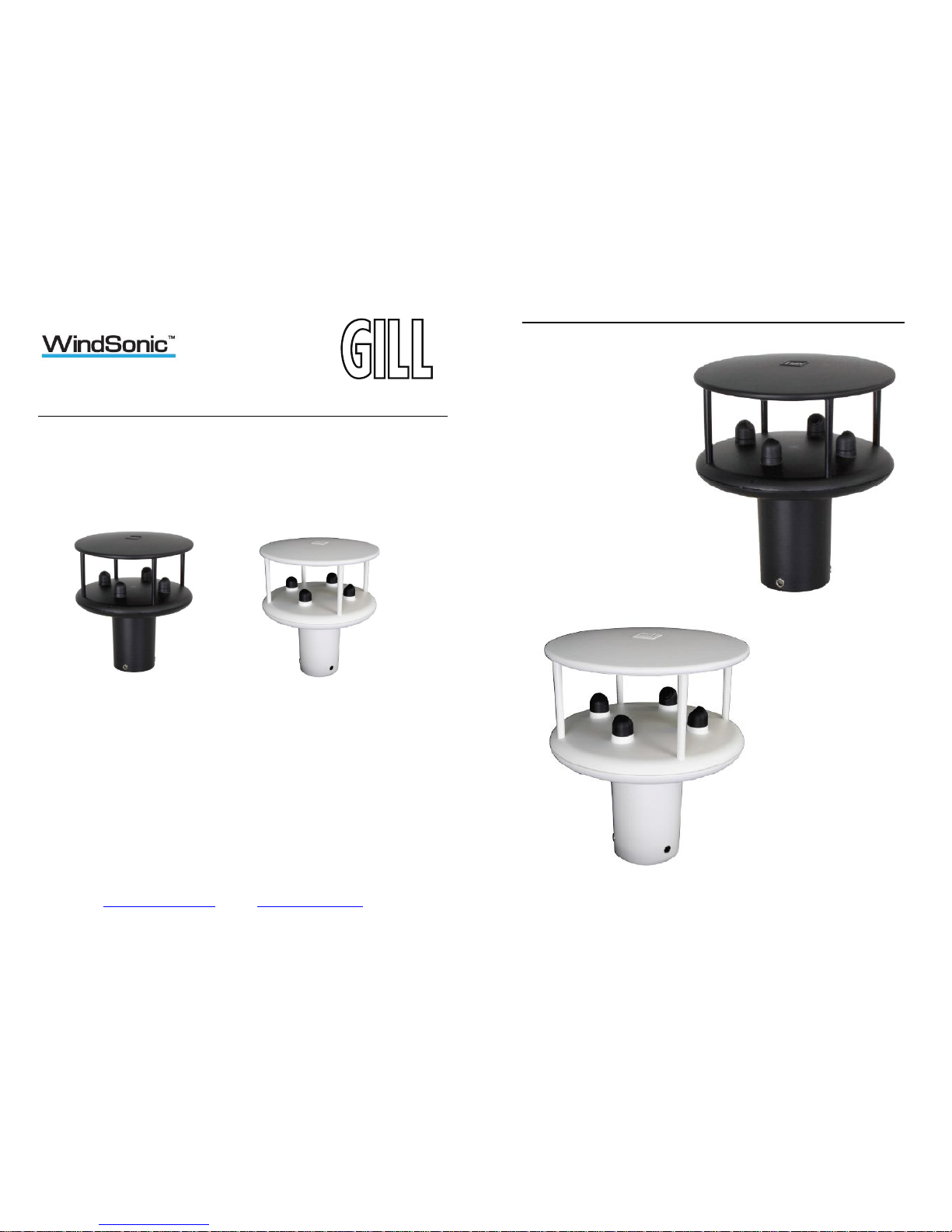
2 INTRODUCTION
The Gill WindSonic wind sensor is a very robust, lightweight unit with no moving parts,
outputting wind speed and direction. The units of wind speed, output rate and formats are all
user selectable.
The WindSonic can be used in conjunction with a PC, data logger or other device, provided
it is compatible with one of the standard communication formats provided by the
WindSonic.
WindSonic (option 2 or 3 only) is designed to connect directly to the Gill WindDisplay unit
to provide a complete wind speed direction system.
WindSonic (options 1, 2 and 3) may be configured using Wind software which is available,
free of charge, from the Gill website www.gillinstruments.com. The output message format
can be configured in Gill format, in Polar or UV (2-axis) format, and to either Polled
(requested by host system) or Continuous output. Alternatively, it can be configured in
NMEA (0183 Version 3). These are described in Section 9 MESSAGE FORMATS.
WindSonic (option 4) SDI-12 may not be re-configured in any Gill output format and format
is SDI-12 (V1.3) and described in Section 14 SDI-12 COMMANDS.
3 FAST TRACK SET-UP
If you are in a hurry to try out the WindSonic (options 1, 2 or 3) and are familiar with Gill
equipment and coupling to a PC using RS232, go to the following sections:
Section 7 INSTALLATION
Section 9 MESSAGE FORMATS
Section 10 CONFIGURING
After you have successfully set up the WindSonic, we strongly advise that you then go back
and read the rest of the manual to ensure that you get the best results from the WindSonic.
WindSonic Doc No 1405 PS 0019 Issue 25 February 2017
6
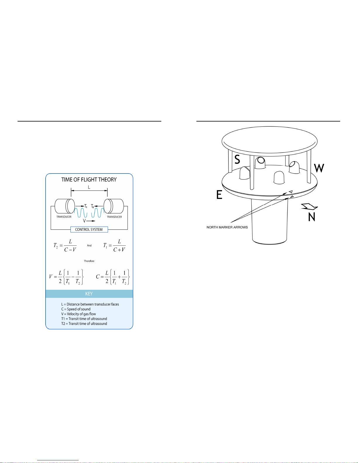
4 PRINCIPLE OF OPERATION
The WindSonic measures the times taken for an ultrasonic pulse of sound to travel from the
North transducer to the South transducer, and compares it with the time for a pulse to travel
from S to N transducer. Likewise times are compared between West and East, and E and W
transducer.
If, for example, a North wind is blowing, then the time taken for the pulse to travel from N
to S will be faster than from S to N, whereas the W to E, and E to W times will be the same.
The wind speed and direction can then be calculated from the differences in the times of
flight on each axis. This calculation is independent of factors such as temperature.
Figure 1 Time of Flight details
WindSonic Doc No 1405 PS 0019 Issue 25 February 2017
7
Figure 2 Compass Points
WindSonic Doc No 1405 PS 0019 Issue 25 February 2017
8
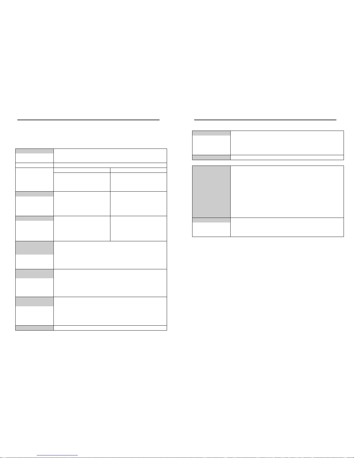
5 SPECIFICATION
This Specification relates to WindSonic Option 1, 2 and 3 WindSonic Sensors fitted
with a Red Tab and WindSonic 75 Option 1, 2 and 3 fitted with an Orange tab (fitted
adjacent to the North Marker arrow).
Output
Units of measure Metres/second (m/s), Knots, Miles per hour (mph),
Kilometres per hour (kph), Feet per minute (fpm)
Output frequency 0.25, 0.5, 1, 2, or 4 outputs per second
Digital Analogue
Parameters
Polar - Speed and Direction
UV - 2 axis, signed Speed
NMEA Speed and Direction
Tunnel - U speed & U Polarity
Polar - Speed and Direction
UV - U Speed and U Polarity
NMEA – Speed and Direction
Tunnel - U Speed & U Polarity
Wind Speed
0 – 5m/s, 0 – 10m/s, 0 – 20m/s,
Range 0 – 60m/s WindSonic
0 - 75m/s WindSonic 75
0 – 30m/s, 0-40m/s, 0 – 50m/s,
0 – 60m/s
Accuracy
2% (at 12m/s) 2% (at 12m/s)
Resolution 0.01 m/s 10 bits
Wind Direction
Range
0 - 359 0 - 359
Or 0 - 539 (Wraparound mode)
Accuracy
2 (at 12m/s) 2 (at 12m/s)
Resolution
1 1
Analogue output
formats (not
Windsonic 75)
0-5V
4-20mA
0-20mA
1% of full scale N.B. Analogue output impedance = 1KΩ (V out)
Load resistance between the Analogue outputs (Pins 8 & 9) and Signal
Ground (Pin 1) must be <= 300 ohms, including cable resistance.
Digital output
formats
Gill
Continuous or Polled (output on request by host system)
Polar (Speed and Direction) or UV (2 axis, signed Speed)
Marine – NMEA NMEA 0183 version 3
Communication
formats
WindSonic Option 1 RS232
WindSonic Option 2 RS232, RS422, RS485 (2 wire Point to Point)
WindSonic Option 3
Baud Rate
RS232, RS422, RS485 (2 wire Point to Point), and Analogue
2400, 4800, 9600, 19200, 38400 Baud Rates
Anemometer status
Status OK and Error codes included in output message
WindSonic Doc No 1405 PS 0019 Issue 25 February 2017
9
Environmental
Moisture protection IP66
Temperature
Operating -35C to +70C Storage -40C to +80C
Humidity Operating <5% to 100%
EMC EN 61326
Standards
Manufactured within ISO9001: 2008 quality system
Power requirement
5 – 30 V DC Option 1 and 2 units (WindSonic).
7 – 30 V DC. Option 3 units (WindSonic).
Current drain depends on variant i.e. RS232 approximately 9mA rising
to 44mA for Analogue variant.
Lowest power consumption is obtained with the following
configuration: -
M2, P20, B3, S9 (approximately 5.5mA at 12v).
12 – 30 V DC Option 1, 2and 3 units (WindSonic 75).
Current drain i.e. RS232 approximately 13mA at 12v dc.
Mechanical
Size / weight 142mm diameter x 163mm 0.5kg
Mounting Pipe mounting 1.75 inches (44.45mm) diameter
Material External - Acrylate Styrene Acrylonitrile, Polycarbonate blend.
The Specification for the Option 4 SDI-12 unit is detailed in Section 14.

WindSonic Doc No 1405 PS 0019 Issue 25 February 2017
10
6 PRE-INSTALLATION
6.1 Equipment supplied
Item Quantity
WindSonic 1
Connector and Mounting Screws comprising:9 Way connector
Connector Contacts
Sealing Gland
Sealing Washer
1
9
1
1
Washer shake proof 3
Screws – M5 stainless steel 3
User Manual, Wind and WindView Software on the CD 1
Wind and WindView software is available free of charge from the Gill website –
http://gillinstruments.com/main/software.html
6.1.1 WindSonic Part Numbers
1405-PK-021 Black WindSonic Option 1 – RS 232 output only
1405-PK-068 White WindSonic Option 1 – RS 232 output only
1405-PK-038 Black WindSonic Option 2 – RS 232, 422 & 485 (point to point) output
1405-PK-072 White WindSonic Option 2 – RS 232, 422 & 485 (point to point) output
1405-PK-040 Black WindSonic Option 3 – RS 232, 422, 485 p to p & analogue output
1405-PK-073 White WindSonic Option 3 – RS 232, 422, 485 p to p & analogue output
1405-PK-100 Black WindSonic Option 4 – SDI-12 output only
1405-PK-110 White WindSonic Option 4 – SDI-12 output only
1405-PK-400 Black WindSonic 75 Option 1- RS232 output only
1405-PK-420 Black WindSonic 75 Option 2 RS 232, 422 & 485 (point to point) output
1405-PK-423 Black WindSonic 75 Option 3 RS 232, 422 & 485 p to p & analogue op.
Optional extras:
Item Part No
Cable 4 Pair, twisted and shielded 24 AWG 026-03156
Cable 3 Pair, twisted and shielded 24AWG
Cable 15 metres (4 pair twisted and shielded 24AWG – Connector
pins attached to one end and stripped wires the other).
WindSonic connector (1 supplied as standard see above)
WindSonic Support Tube 0.5 metre (Aluminium)
026-02660
1405-10-080
1405-PK-069
1405-30-056
Bracket for mounting to a Pole, includes a WindSonic Adaptor 1771-PK-115
WindSonic Doc No 1405 PS 0019 Issue 25 February 2017
11
6.2 Packaging
Whilst the WindSonic is being moved to its installation site, the unit should be kept in its
inner packaging. All the packaging should be retained for use if the unit has to be returned at
any time, or if a self-test is performed.
6.3 Installation requirements
Host system - One of the following:
PC fitted with a suitable interface to match the chosen communication format
(RS232, RS422, or RS485 (point to point), compatible with the WindSonic option
selected,
and a suitable Terminal Emulation software package. For example HyperTerminal for
Windows or Wind Software that is available from the Gill website at
http://gillinstruments.com/main/software.html.
Gill WindDisplay (WindSonic option 2 or 3 only).
Other equipment with input/output compatibility to the WindSonic Option selected.
For example, Data loggers.
Cable - To connect between the WindSonic and the host system
See Section 7.3.1 Cable type for cable specification.
There are restrictions on the maximum cable lengths for correct operation.
The cable should be routed up the inside of the mounting tube.
Mounting tube (e.g. 0.5 metre long Gill part 1405-30-056)
Standard tube 1.75 inches (44.45mm) Outside Diameter x 3mm wall thickness. Note it is
important that the correct diameter tube is used to prevent damage to the
WindSonic lower moulding when tightening the screws.
See Figure 3, Alignment & Mounting Details on page 26.
For non-hostile environments, Aluminium tube can be used.
For hostile environments, you should select a material suitable for the intended
environment. For example, stainless steel 316 for marine use.
Mounting Bracket (Gill Part 1771-PK-115)
WindSonic Doc No 1405 PS 0019 Issue 25 February 2017
12
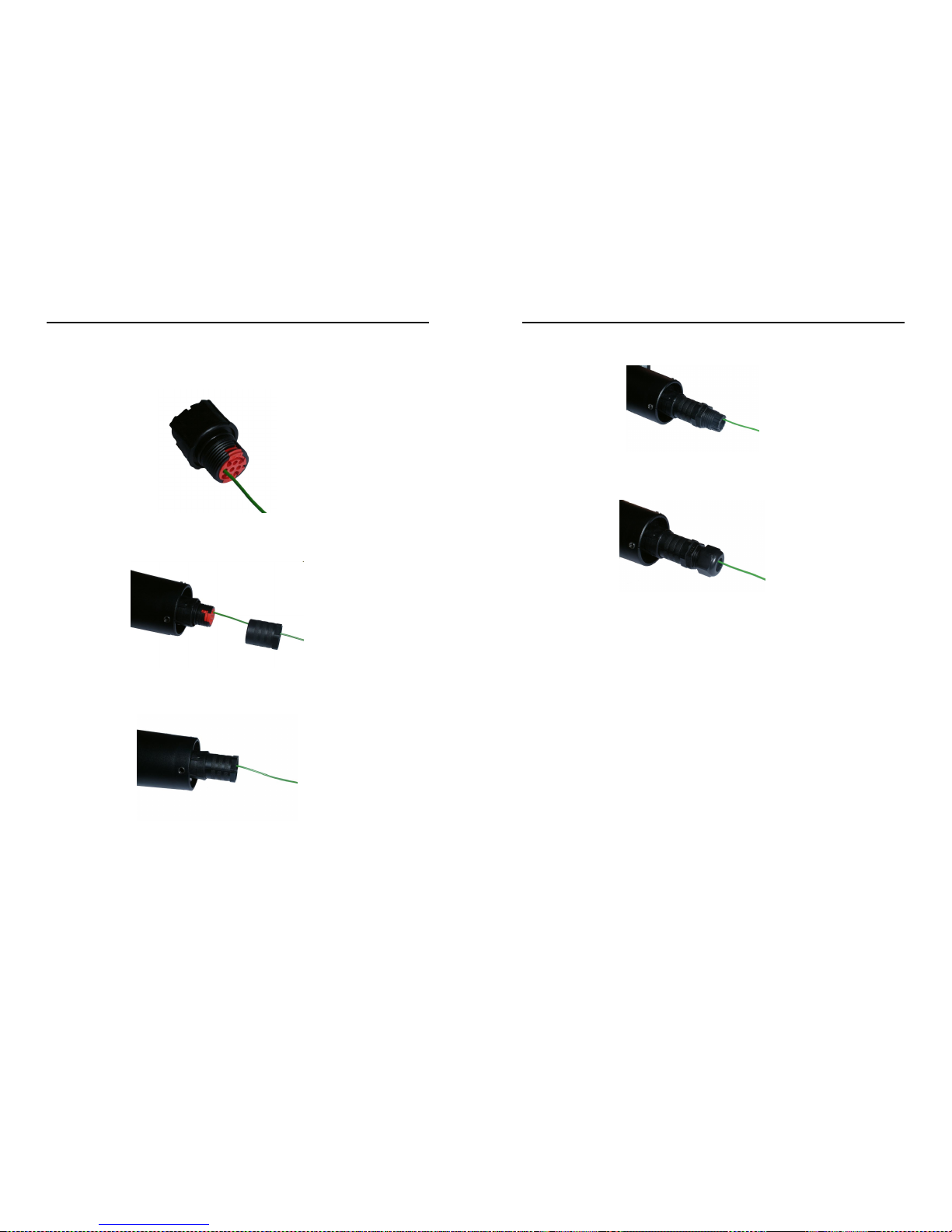
6.4 Cable Assembly
Open the pack of parts provided with the WindSonic or as 1405-PK-069
Trim back the screened cable outer and screen sleeves 40mm.
Trim back the screen drain wires flush with the outer sleeve.
Strip back the connection wires by 5mm and tin solder.
Solder the contact pins to the wires (please note that the connector supplies the correct strain
relief for cables with an outside diameter of 6-12mm).
Put the parts on the cable in the order as shown below.
Whilst squeezing the red retainer in the direction of ARROWS A, pull in the direction of
ARROW B.
A
A
B
Your connector should now resemble the connector in the picture below.
Screen Twisted Pair Cable
5 mm
40 mm Screen drain wires cut flush
WindSonic Doc No 1405 PS 0019 Issue 25 February 2017
13
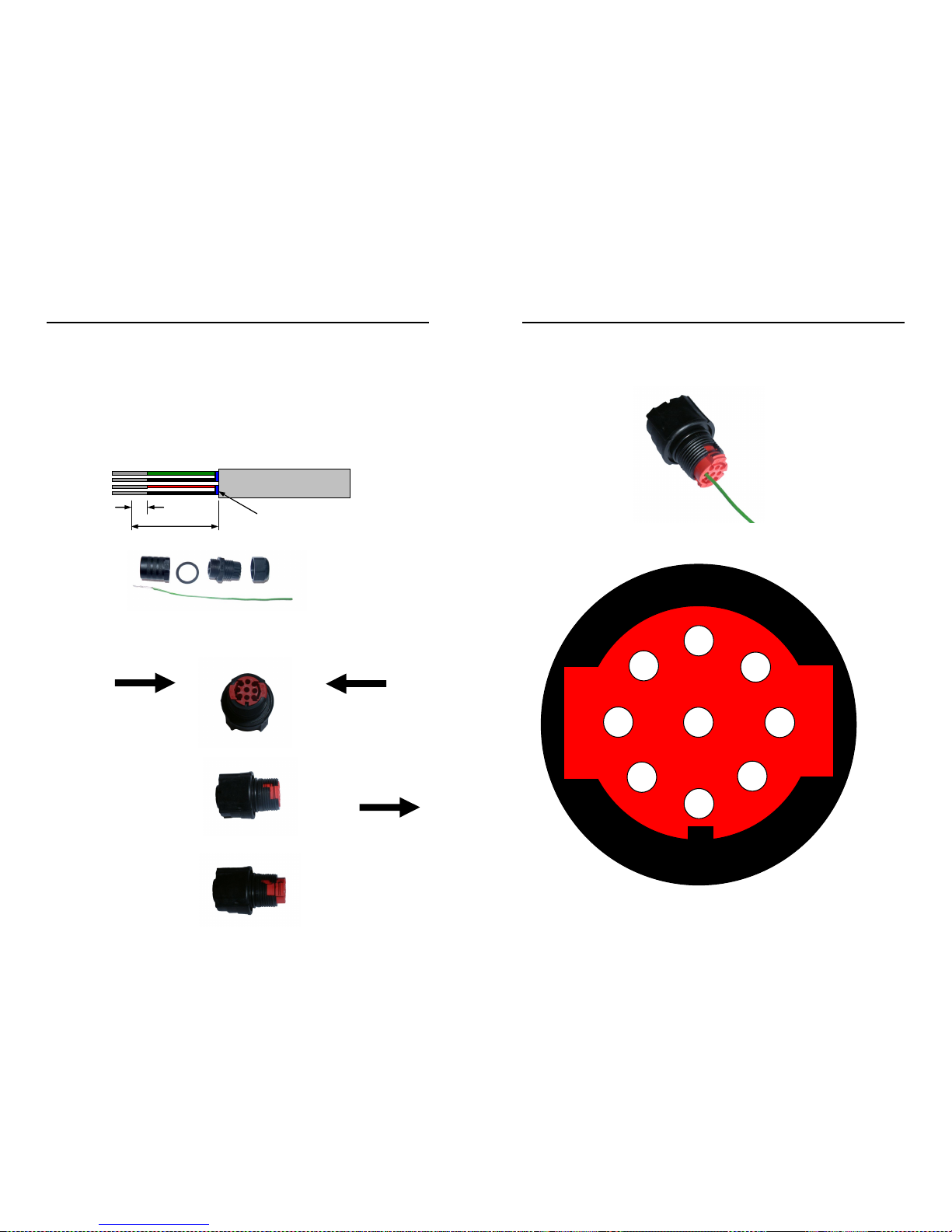
Insert each contact pin until you feel a slight click. If you have inserted the contact into the
incorrect hole it can be removed at this point by simply pulling it out. Please note there will
be some resistance.
Rear View of Connector
1
9 5 3
7
4 2 6 8
WindSonic Doc No 1405 PS 0019 Issue 25 February 2017
14
Continue to insert all of the contacts you require. Once all of the contacts are inserted push
the red retainer into place. NB. The retainer can only be pushed back into place if the
contacts are fully engaged.
Fit the connector to the WindSonic so that you can finish assembling the connector.
Screw the back shell onto the connector until it is fully in place. Please note that the final
rotations can be slightly stiff.
WindSonic Doc No 1405 PS 0019 Issue 25 February 2017
15
Now screw the next part of the connector into place.
Now screw the cable-clamping nut into place.
The connector can now be removed from the WindSonic.
NOTE: To disassemble the connector, reverse this procedure.
For spares purposes the complete WindSonic Souriau Clipper connector comprises of:-
9 way Connector CLF1201.
Connector female contact CM10SS10MQ.
Sealing Gland Clipper size1 CL101021 (suitable for cables 6-12mm outer diameter).
WindSonic Doc No 1405 PS 0019 Issue 25 February 2017
16
7 INSTALLATION
Do NOT remove the black “rubber” transducer caps. Warranty is void if the coloured
security seal is damaged or removed.
7.1 Installation Guidelines
The WindSonic has been designed to meet and exceed the stringent standards listed in its
specification. Operating in diverse environments all over the world, WindSonic requires no
calibration and adjustment whatsoever.
As with any sophisticated electronics, good engineering practice should be followed to
ensure correct operation.
Always check the installation to ensure the WindSonic is not affected by other
equipment operating locally, which may not conform to current standards, e.g.
radio/radar transmitters, boat engines, generators etc.
Guidelines –
o Avoid mounting in the plane of any radar scanner – a vertical separation
of at least 2m should be achieved.
o Radio transmitting antennas, the following minimum separations (all
round) are suggested
VHF IMM – 1m
MF/HF – 5m
Satcom – 5m (avoid likely lines of sight)
Use cables recommended by Gill. If cables are cut and re-connected incorrectly
(perhaps in a junction box) then EMC performance may be compromised if cable
screen integrity is not maintained.
Earth loops should not be created – wire the system in accordance with the
installation guidelines.
Ensure the power supply operates to the WindSonic specification at all times.
Avoid turbulence caused by surrounding structures that will affect the accuracy of the
WindSonic such as trees, masts and buildings. Ideally sensors should be mounted on the
prevailing wind side of the site.
The WMO make the following recommendations:
The standard exposure of wind instruments over level open terrain is 10m above the
ground. Open terrain is defined as an area where the distance between the sensor and
any obstruction is at least 10 times the height of the obstruction.
If mounting on a building then theoretically the sensor should be mounted at a height of 1.5
times the height of the building.
If the sensor is to be mounted on a mast boom, part way up a tower or mast, then the boom
should be at least twice as long as the minimum diameter or diagonal of the tower. The
boom should be positioned on the prevailing wind side of the tower.
WindSonic Doc No 1405 PS 0019 Issue 25 February 2017
17
7.2 Bench system test
Note: Prior to physically mounting the WindSonic in its final location, we
strongly recommend that a bench system test is carried out to confirm the
system is configured correctly, is fully functional and electrically
compatible with the selected host system and cabling (preferably utilising
the final cable length). The required data format, units, output rate, and
other options should also all be set up at this stage.
7.3 Electrical
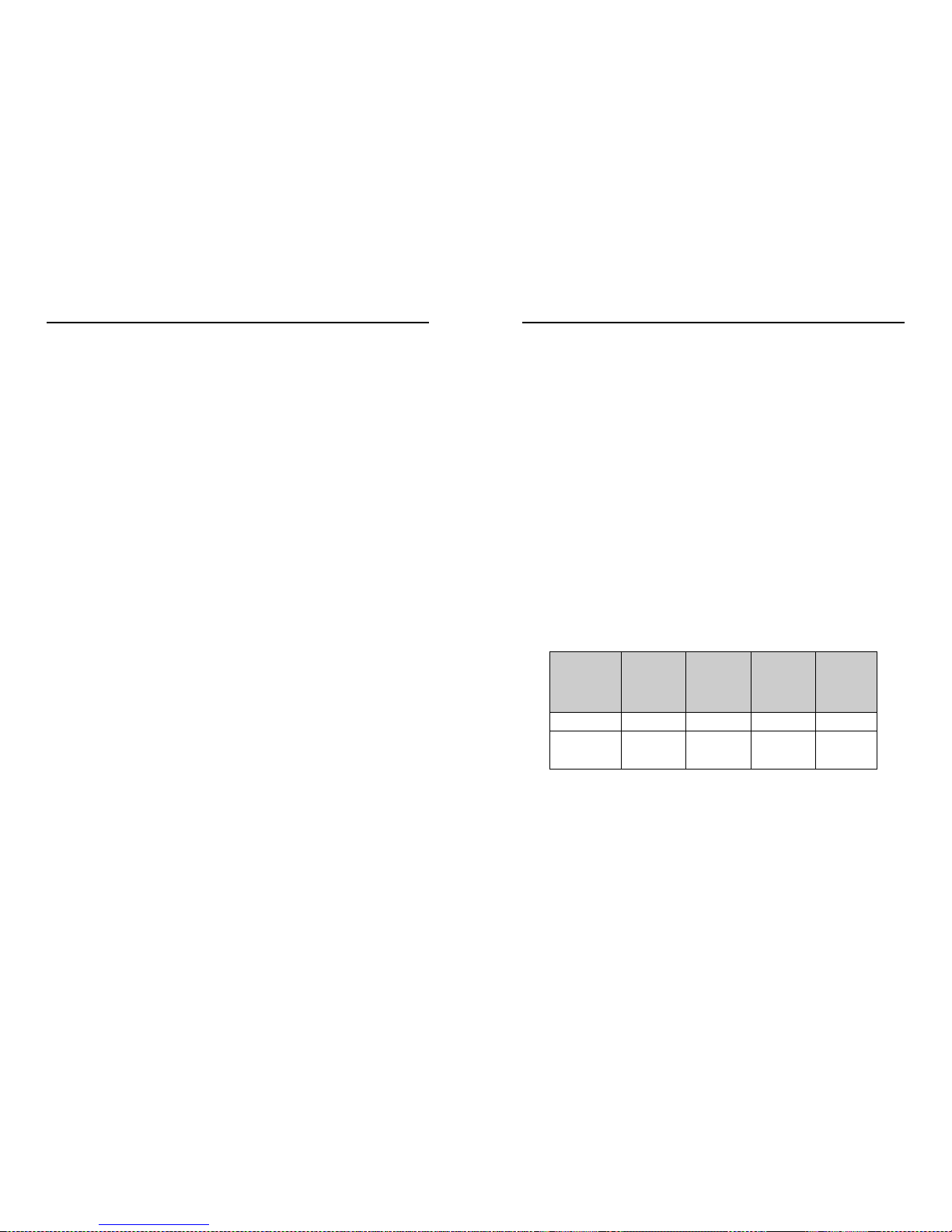
7.3.1 Cable
Cable type
A RS422 compatible cable should be used, with the number of twisted pairs matching the
application.
Generic description – Twisted pairs with drain wire, screened with aluminised tape,
with an overall PVC sheath of 6mm-12mm outer diameter. Wire size 7/0.2mm (24 AWG).
The table shows some suitable manufacturers’ references; other manufacturers’ equivalents
can be used.
Application No. of pairs
Gill ref.
24 AWG
Belden ref.
24 AWG
Batt
electronics
ref.
24 AWG
WindDisplay 2 - 9729 -
RS 232 3 026-02660 9730 91030
RS 422 4 026-03156 9728 91199
WindSonic Doc No 1405 PS 0019 Issue 25 February 2017
18
Cable length
The maximum cable length is dependent on the chosen communication format (RS232,
RS422 or RS485 (point to point), the baud rate, and, to a lesser extent, on the cable type and
the local electrical ‘noise’ level.
The table shows the typical maximum lengths at the given baud rates, using the
recommended cable. If any problems of data corruption etc. are experienced, then a slower
baud rate should be used. Alternatively, a thicker or higher specification cable can be tried.
WindSonic
Option
Communication format Baud rate Max. cable length
Option 1, 2 and 3 RS232 9600 6.5 m (20 ft)
Option 2 and 3 RS422 or RS485 point to
point
9600 1 km (3200 ft)
Option 3
Analogue – Voltage o/p N/A 6.5 m (20 ft)
Analogue – Current o/p
N/A
Resistance dependent
(max 300 Ω)
7.3.2 Power supply
WindSonic Option 1 and 2 Units; Require a DC supply of between 5V – 30 V DC (30V DC
max).
WindSonic Option 3 Units; Require a DC supply of between 7V– 30 V DC (30V DC
max).
WindSonic current drain depends on variant i.e. Option 1, RS232 approximately 9mA at 12v
dc rising to 44mA for Analogue variant.
Lowest power consumption is obtained with the following configuration: M2, P20, B3, S9 (approximately 5.5mA at 12v).
WindSonic 75 Option 1, 2 and 3 Units; Require a DC supply of between 12V – 30 V
DC (30V DC max).
WindSonic 75 Option 1 and 2 current drain is typically approximately 13mA at 12v dc.
WindSonic Doc No 1405 PS 0019 Issue 25 February 2017
19
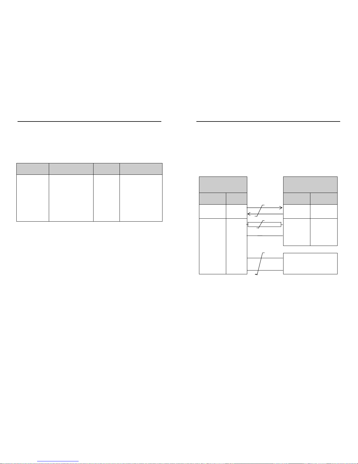
7.4 Connecting to a PC using RS232 (Option 1 Sensor)
Notes
1. The cable length for reliable operation is limited to 6.5m (20ft).
(See Section 7.3.1 Cable length.)
2. For longer cable runs, we recommend using the WindSonic configured with RS422
output, and a RS422/232 converter at the PC.
3. Wiring connections below are not applicable to WindSonic Options 2 and 3 set for
RS232 operation.
WindSonic
9 Way circular connector
Typical PC or RS232 to USB
Converter Serial Port
9 Way ‘D’ Connector
Signal names
Pin nos. Cable – 3 twisted
pairs
Signal names Pin no's
TXD
RXD
5
7
RXD
TXD
2
3
Signal
Ground
1
Signal Ground 5
Do NOT
connect
at this end
N/A Screen and drain
wires
Chassis
ground
N/A
V supply -
V supply +
2
3
–
+
DC Power supply
(See Para 7.3.2)
Default Settings
The WindSonic Option 1 unit is factory configured with the following default settings:
M2, U1, O1, L1, P1, B3, H1, NQ, F1, E3, T1, S4, C2, G0, K50,
WindSonic Doc No 1405 PS 0019 Issue 25 February 2017
20
7.5 Connecting WindSonic Option 2 or 3 set for default
RS422 to a PC using an RS232 Safe Mode Connection.
WindSonic
9 Way circular connector
PC
Typical 9 Way ‘D’ Connector
Signal names
Pin nos. Cable – 3 twisted
pairs
Signal names Pin no's
TXD
RXD
5
7
RXD
TXD
2
3
Signal
Ground
1
Signal Ground 5
Do NOT
connect
at this end
N/A Screen and drain
wires
Chassis
ground
N/A
V supply +
V supply -
2
3
+ – DC Power supply
(See Para 7.3.2)
1. Connect the Option 2 or 3 WindSonic as per the above connection diagram.
2. With WindSonic power off, set up a HyperTerminal connection as per Page 46 but
with the Baud rate set to 19200 (this can be at variance with the original
WindSonic Baud rate setting).
3. Hold down the * character (shift 8) and then apply power to the WindSonic. After
approximately 3 seconds the unit will respond with Safe Mode.
4. To change output communication from RS422 to RS232 then remove any * characters
on screen.
5. Type E3 and press Enter (changes E2 setting to E3).
6. E3 will be seen twice on screen to confirm the setting change to RS232 has occurred.
7. Change any other configuration settings as required.
8. Type Q and press Enter to go back into measurement mode (garbled data may appear
on screen if the original WindSonic Baud rate setting is not 19200bauds).
9. If required close the 19200-baud HyperTerminal connection and re-open at the
WindSonic Baud rate. If a continuous data mode has been previously chosen then data will
scroll on screen.
(Note that supply voltage connections are reversed compared to the Option 1 RS232
unit. Damage will not occur from a reverse voltage connection).
7.6 Changing an Option 2 or 3 Sensor set for RS232 back
to RS422.
Connect the Option 2 or 3 WindSonic as per Para 7.5.
Repeat instructions shown in Para 7.5 except that in Safe Mode set the E Command to E2
etc.
WindSonic Doc No 1405 PS 0019 Issue 25 February 2017
21
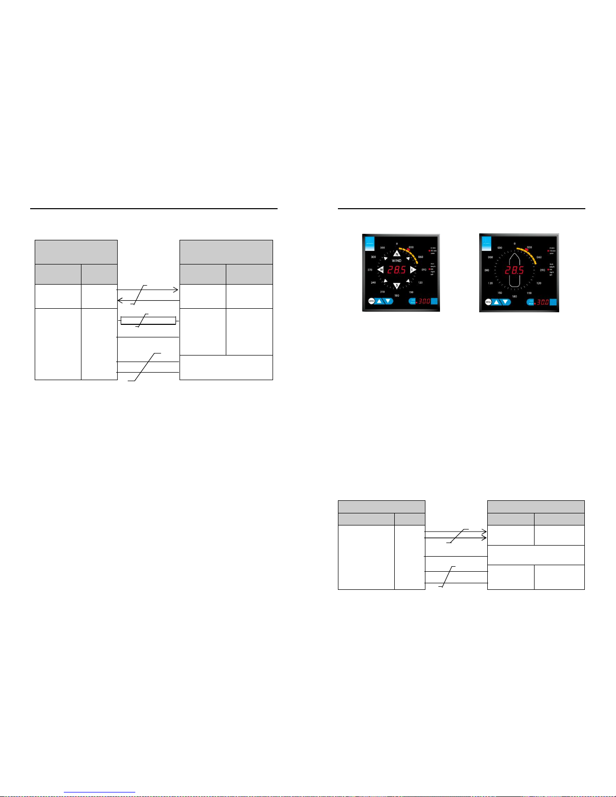
7.7 Connecting to a Gill WindDisplay
Meteorological Display Marine Display
The WindSonic is designed to interface with the Gill WindDisplay unit to provide a
complete wind speed and direction system.
To interface to a non NMEA WindDisplay the WindSonic is set by default for Polar
(M2) and 9600 (B3) configuration settings.
When coupled to a WindDisplay, the WindSonic can be used as supplied, however if a
fault occurs the WindDisplay may lock into the last valid reading. Re-configuring the
WindSonic to Fixed Field output (O2) will ensure that any fault is flagged on the
WindDisplay.
After coupling to a WindDisplay, the Wind Speed units and the Averaging period can
be selected using the WindDisplay controls. See the WindDisplay User Manual.
Note that although the WindDisplay can display wind speed in various units, these are
calculated within the WindDisplay. The data coming to the WindDisplay must be in
metres/sec (the factory default output setting).
Notes
1. WindSonic Option 2 or 3 must be used set for RS422 output (E2 Mode).
2. Use the WindSonic in the factory default mode for the Meteorological Wind
Display – i.e. do not reconfigure.
3. If used with a Marine NMEA 9600 Baud or4800 Baud WindDisplay set the
Wind Sonic for NMEA (e.g. M5) and 9600 Baud (B3) or4800 Baud (B2).
4. The WindDisplay can provide power to the WindSonic.
WindSonic Connector Cable WindDisplay
Signal name Pin no. 2 twisted pairs Signal name Terminal no.
TXD +
TXD –
4
5
TXD +
TXD –
8
7
No connection N/A Screen and drain
wires
Ground (Earth)
V supply +
V supply -
2 3
+
O
2
1
 Loading...