

Page 1
UK +44 (0) 1536 0614 070 [email protected]
www.windowmaster.com
Other markets +45 4567 0300 [email protected]
WSC 5 install 1809-Firmware v093 - UK M00572 ©WindowMaster 2012, 2018 ®WindowMaster is a registred trademark used under the license by WindowMaster International A/S
WindowMaster International A/S, Skelstedet 13, DK-2950 Vedbæk
FlexiSmoke
™
WSC 520 / 540 / 560
Installation instruction
(Version 1809 – from firmware version 0.93)
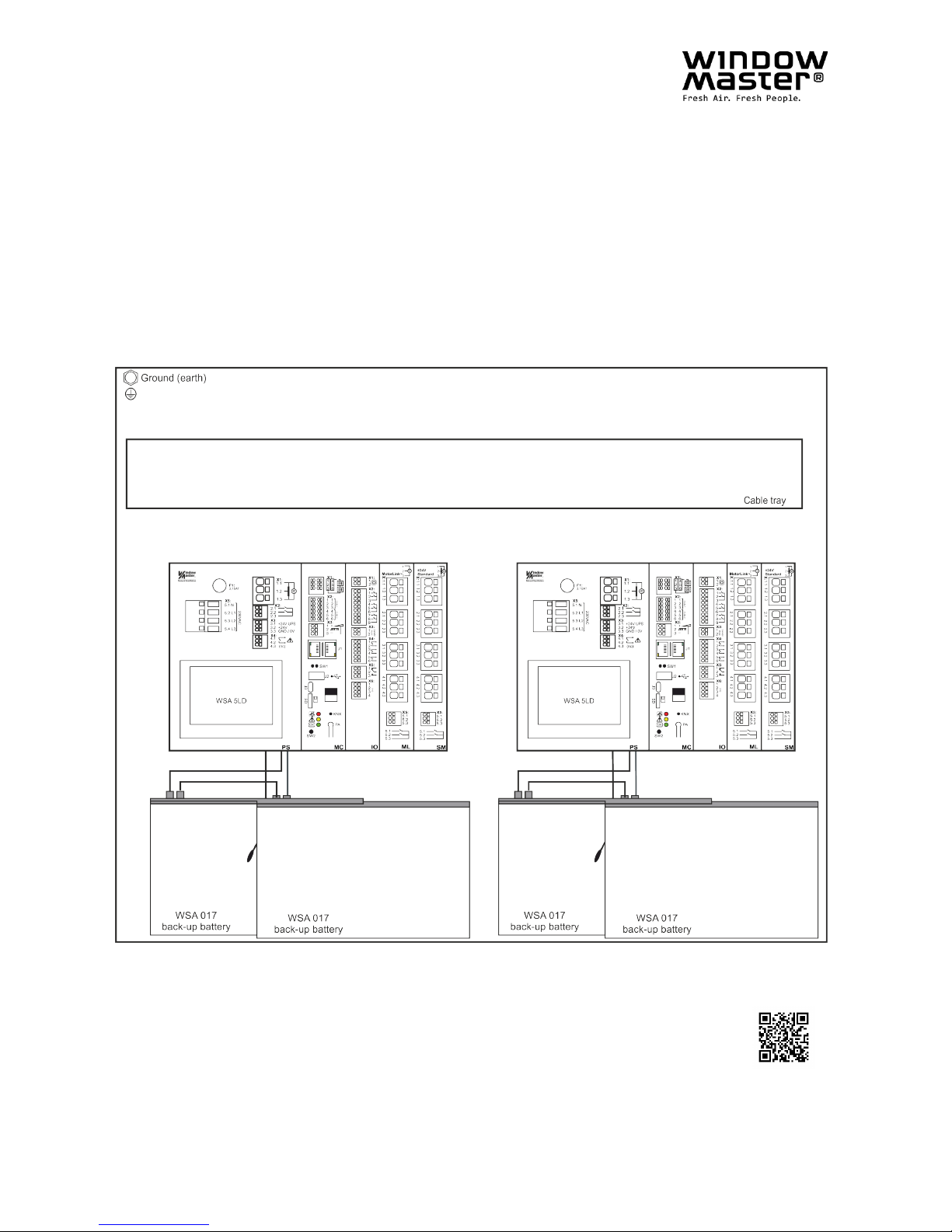
The drawing shows WSC 540 KIMS KIMS
Save this installation instruction to the end user
Scan the QR-code and watch our
installation video showing how to
configure the FlexiSmoke
TM
Page 2

2
Contents
1 Safety information ....................................................................................................................................................... 4
1.1 Safety ................................................................................................................................................................ 4
1.2 230V AC ............................................................................................................................................................ 4
1.3 Back-up batteries ............................................................................................................................................... 4
1.4 Application ......................................................................................................................................................... 4
1.5 Cable routing and electrical connection ................................................................................................ ............. 4
2 Structure of the smoke panel ..................................................................................................................................... 5
3 Variants of panels........................................................................................................................................................ 7
3.1 Number of motor lines, inputs and outputs depending on the combination of the three expansion modules .... 8
3.2 Examples with FlexiSmoke™ ............................................................................................................................ 8
3.3 Max numbers of motors per motor line which can be connected per module
.......................................................... 9
4 Modules, accessories, spare parts .......................................................................................................................... 10
5 Technical data ........................................................................................................................................................... 11
6 Mounting .................................................................................................................................................................... 13
7 Installation ................................................................................................................................................................. 13
7.1 Cable routing ................................................................................................................................................... 13
7.2 Cables into housing ......................................................................................................................................... 13
7.3 Connection of safety earth wire and 230V AC ................................................................................................. 14
7.4 Installation of the break glass unit, ventilation keypad and smoke detector..................................................... 14
7.5 Assembly instructions ...................................................................................................................................... 14
8 Cable dimensioning .................................................................................................................................................. 14
8.1 Maintaining the cable functions ....................................................................................................................... 14
8.2 Formula for the calculation of the maximum motor cable length...................................................................... 14
8.3 Max. cable Length ........................................................................................................................................... 15
8.3.1 Max cable length – ±24V standard motors ................................................................................................. 15
8.3.2 Max cable length – motors with MotorLink® ................................................................................................ 16
8.3.3 Max cable length – Pyrotechnic gas generator ........................................................................................... 16
9 Cable plan for connection to WSC 520 / WSC 540 / WSC 560 ............................................................................... 17
10 Description of modules ............................................................................................................................................. 18
10.1 WSA 5PS power supply module 20A .............................................................................................................. 18
10.2 WSA 5MC overall control module .................................................................................................................... 20
10.3 WSA 5IO input/output module ......................................................................................................................... 25
10.4 WSA 5SM standard motor module .................................................................................................................. 27
10.5 WSA 5ML MotorLink® motor module ............................................................................................................... 29
11 Cable monitoring of motors ..................................................................................................................................... 30
11.1 Usage of non-WindowMaster motors .............................................................................................................. 31
12 Back-up batteries ...................................................................................................................................................... 31
13 Touch screen ............................................................................................................................................................. 31
13.1 Icons ................................................................................................................................................................ 32
13.2 Rotation of the touch screen ............................................................................................................................ 32
14 Configuration – main menu ...................................................................................................................................... 32
14.1 Motor lines – motor groups – smoke zones ..................................................................................................... 33
14.1.1 Examples with motor lines / motor groups / smoke zones .......................................................................... 33
14.2 Motor line ......................................................................................................................................................... 34
14.2.1 Motor line - numbering ................................ ................................ ................................................................ 34
14.2.2 Motor line - configuration ............................................................................................................................ 34
14.2.3 Colour code - motor line ............................................................................................................................. 35
14.3 Motor group ..................................................................................................................................................... 35
14.3.1 Motor group - configuration......................................................................................................................... 36
14.3.2 Colour code – motor group ......................................................................................................................... 36
14.4 Break glass unit ............................................................................................................................................... 36
14.4.1 Break glass unit – configuration .................................................................................................................. 36
14.4.2 Colour code – break glass unit ................................................................................................................... 37
14.5 Smoke zone ..................................................................................................................................................... 37
14.6 Local input ....................................................................................................................................................... 39
14.6.1 Numbering of local inputs ........................................................................................................................... 39
14.6.2 Local input - configuration........................................................................................................................... 39
14.6.3 Usage of wind/rain sensors - WLA 33x ....................................................................................................... 40
14.7 Local output ..................................................................................................................................................... 41
14.7.1 Numbering of local output ........................................................................................................................... 41
14.7.2 Local output - configuration ........................................................................................................................ 42
14.8 Weather station type ........................................................................................................................................ 43
14.9 Sequence control ............................................................................................................................................. 43
14.10 Magnetic clamp (magnetic door retainer) ........................................................................................................ 45
14.11 Pyrotechnic gas generator ............................................................................................................................... 46
14.12 Alarm output .................................................................................................................................................... 46
14.13 CAN bus .......................................................................................................................................................... 47
14.14 Network ........................................................................................................................................................... 48
14.15 Fieldbus ........................................................................................................................................................... 49
14.15.1 KNX-bus ..................................................................................................................................................... 49
14.15.2 BACnet ....................................................................................................................................................... 49
Page 3

3
14.16 Log in ............................................................................................................................................................... 50
14.17 Configuration files on SD ................................................................................................................................. 51
14.18 Configuration files on USB............................................................................................................................... 52
14.19 System............................................................................................................................................................. 53
14.19.1 Service timer ............................................................................................................................................... 53
15 Status – main menu................................................................................................................................................... 54
16 Manual operation – main menu ................................................................ ................................................................ 54
17 Configuration missing – main menu........................................................................................................................ 55
18 Hardware error – main menu .................................................................................................................................... 55
18.1 Error on the Power supply ............................................................................................................................... 55
18.1.1 Blown fuse – 20A fast ................................................................................................................................. 56
18.1.2 Blown fuse – 3.15A slow............................................................................................................................. 56
19 Manage another WSA MC module – main menu..................................................................................................... 56
20 View all details – main menu .................................................................................................................................... 57
21 Remote control of FlexiSmoke™ ............................................................................................................................. 57
22 Commissioning and test run .................................................................................................................................... 58
22.1 The control ventilation panel is completely installed, without the operating voltage applied ............................ 58
22.2 With mains voltage, without accumulator......................................................................................................... 58
22.3 With mains voltage, with accumulator ............................................................................................................. 58
22.4 Ventilation keypad ........................................................................................................................................... 58
22.5 Break glass unit WSK 501/502 ........................................................................................................................ 58
22.6 Smoke detectors .............................................................................................................................................. 59
22.7 Emergency power supply test .......................................................................................................................... 59
22.8 Wind/rain detector ........................................................................................................................................... 59
23 Maintenance ............................................................................................................................................................... 59
23.1 Maintenance agreements ................................................................................................................................ 59
23.2 Replacement modules ..................................................................................................................................... 60
23.2.1 Replacement of 5PS, 5IO, 5ML and 5SM modules .................................................................................... 60
23.2.2 Replacement of 5MC module ..................................................................................................................... 60
24 Declaration of Conformity and CE certificate ......................................................................................................... 60
Page 4

4
1 Safety information
1.1 Safety
Only allow correspondingly trained, qualified and skilled personnel to carry out installation work.
Reliable operation and the avoidance of damage and hazards are only guaranteed if installation and settings are carried
out carefully in accordance with these instructions.
There may be personal danger by electrically operated windows:
- the forces occurring in the automatic mode can be such that parts of the body could get crushed
- when opened, actuators (spindles) could protrude into the room
For this reason, measures have to be taken prior to starting up the actuators which exclude the danger of injury.
For safety reasons we recommend to install opening restrictors on bottom-hung windows.
In the event that windows are subjected to rain and/or high wind loads, we recommend connecting a wind/rain sensor to
the smoke ventilation panel for the automatically closing of the windows.
The smoke ventilation panel is to be located in a safe place, protected from the effects of fire and smoke.
The smoke ventilation panel is to be surface mounted.
The smoke ventilation panel has two energy suppliers: 230V AV and back-up batteries.
The manufacturer does not assume any liability for possible damage resulting from inappropriate use.
1.2 230V AC
230VAC can cause death, severe injury or considerable damage to assets.
The connection of the smoke ventilation panel is reserved for qualified personnel.
Disconnect all poles of the panel from the supply voltage prior to opening, installation or assembling.
Installation and use according to the national regulations.
1.3 Back-up batteries
Back-up batteries 2 batteries per 20A-section (i.e. WSC 520 = 2 pcs, WSC 540 = 4 pcs and WSC 560 = 6 pcs.) can cause
severe injury or considerable damage to assets.
The connection of the smoke ventilation panel is reserved for qualified personnel.
Disconnect all poles of the panel from the back-up batteries prior to installation or assembling.
Ensure that the mains cable can be switched via an external or customer-supplied two-pole switch element or a switch
element controlling all poles – see section 7.1 “Cable routing”
Installation and use according to the National regulations.
Dispose of used batteries according to the National regulation.
CAUTION
RISK OF EXPLOSION IF BATTERIES ARE REPLACED BY AN INCORRECT TYPE.
1.4 Application
The smoke ventilation panel is exclusively designed for the automatic opening and closing of smoke extraction systems,
windows, flaps or doors.
Always check that your system meets the valid national regulations.
Pay particular attention to the opening cross section, the opening time and opening speed.
The cable cross sections depend on the cable length and current consumption (amperage).
1.5 Cable routing and electrical connection
Fuse the 230V AC power supply cable separately on site.
Cable routing and connection - adhere to national regulations.
Establish the cable types, if necessary, with the local approval bodies or the fire protection authority.
Do not conceal flexible cables.
Junction box must be accessible for maintenance purposes.
Disconnect all poles of the mains voltage and the back-up batteries prior to starting maintenance work or making changes
to the system.
Secure the system to prevent unintentional switching on again.
Route all low voltage cables (24V DC) separate from the power current cables.
Design cable types, lengths and cross sections in accordance with the technical information.
Cable specifications is a guide only, the overall responsibility resides with the electrical contractor on site.
Installation must be in accordance with the national electrical regulations.
Page 5
5
2 Structure of the smoke panel
Sections
The FlexiSmoke™ smoke ventilation panel is available in three different sizes 20A, 40A and 60A. The smoke ventilation
panel consists of 20A-sections, thus WSC 520 contains one section, WSC 540 two sections and WSC 560 three sections.
Modules
Each section contains the power supply module WSA 5PS, the overall control module WSA 5MC and 3 slots for
expansion modules. The overall control module WSA 5MC is available with or without field bus interface for KNX or
BACnet IP.
At the 3 slots the expansion modules input/output module WSA 5IO, ± 24V standard motor module WSA 5SM or the
MotorLink® motor module WSA 5ML can be connected. The type and number of the modules are specifically to suit the
smoke panel required function.
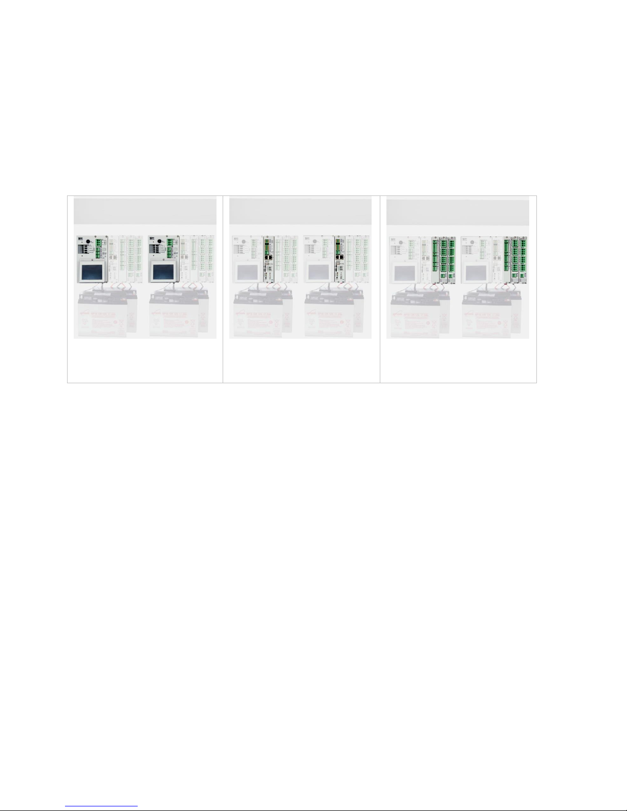
Modules in the FlexiSmoke™ (example of a WSC 540)
WSA 5PS power supply module
– one module in each section
WSA 5MC overall control module
– one module in each section
Free slots for connection of
expansion modules type WSA
5IO, WSA 5SM and/or WSA 5ML
– 3 free slots in each section
Selection of modules
Expansion modules are selected specifically for the task.
Example of module selection:
– 1 input/output module and no additional modules
– 1 input/output module and 1 ±24V standard motor module
– 3 ±24V standard motor modules
The expansion modules are to be plugged in the three slots 3, 4 and 5.
When ordering and by delivery is the expansion module position (as standard):
If an input-/output module is selected it is inserted in the first slot. If further modules are inserted, the input-/output modules
are inserted before the motor modules and the MotorLink® motor modules are inserted before the ±24V motor modules.
On an existing panel the modules can be placed in the best suited slot.
Installation of modules may only be done when there is no power on the panel (no battery or power on).
The item no. of the panel specifies the type and mounting of the expansion modules in the section/sections
- see "Variants of panels" for more information
Motor groups and motor lines
A motor group consists of one or more motor lines and all the motor lines are operated simultaneously.
Each 20A section contains one 20A motor line for connection of ±24V standard motors on the WSA 5PS module. If more
motor lines are needed, one or more motor modules WSA 5SM are inserted. Each motor module contains four motor
lines.
For connection of motors with MotorLink® insert one or more modules WSA 5ML. Each motor module contains four motor
lines.
It is possible to insert both motor module types in the same 20A section, thus the section will operate both ±24V standard
motors and motors with MotorLink®.
A 20A-section can contain up to 13 ±24V standard motor lines or 12 MotorLink® motor lines as well as 1 ±24V standard
motor line and the total power consumption of all the motors must not exceed 20A.
Adding panels
The smoke ventilation panel can be expanded by adding more FlexiSmoke™ panels in the CAN inputs on the WSA 5MC
module. The CAN cable between two smoke ventilation panels must not exceed 250m and the total cable length must not
exceed 1000m.
Page 6
6
Break glass unit
Break glass unit type WSK 50x are to be used together with FlexiSmoke™. The units are configured and assigned to
smoke zones via the touch screen in the smoke ventilation panel.
Inputs
All inputs and outputs on the FlexiSmoke™ smoke ventilation panel can be freely configured – this means that they can be
assigned to functions across modules and 20A-sections.
Cabling
FlexiSmoke™ uses bus
technology and the overall
cabling for break glass units,
smoke detectors and keypads is
significantly reduced compared
to other types of smoke panels:
– the break glass units are
series connected, therefore is
not necessary to cable from
each break glass unit to the
smoke ventilation panel
– keypads for ventilation and
smoke detectors are
connected directly to the
break glass units type WSK
501/502 in the smoke zones
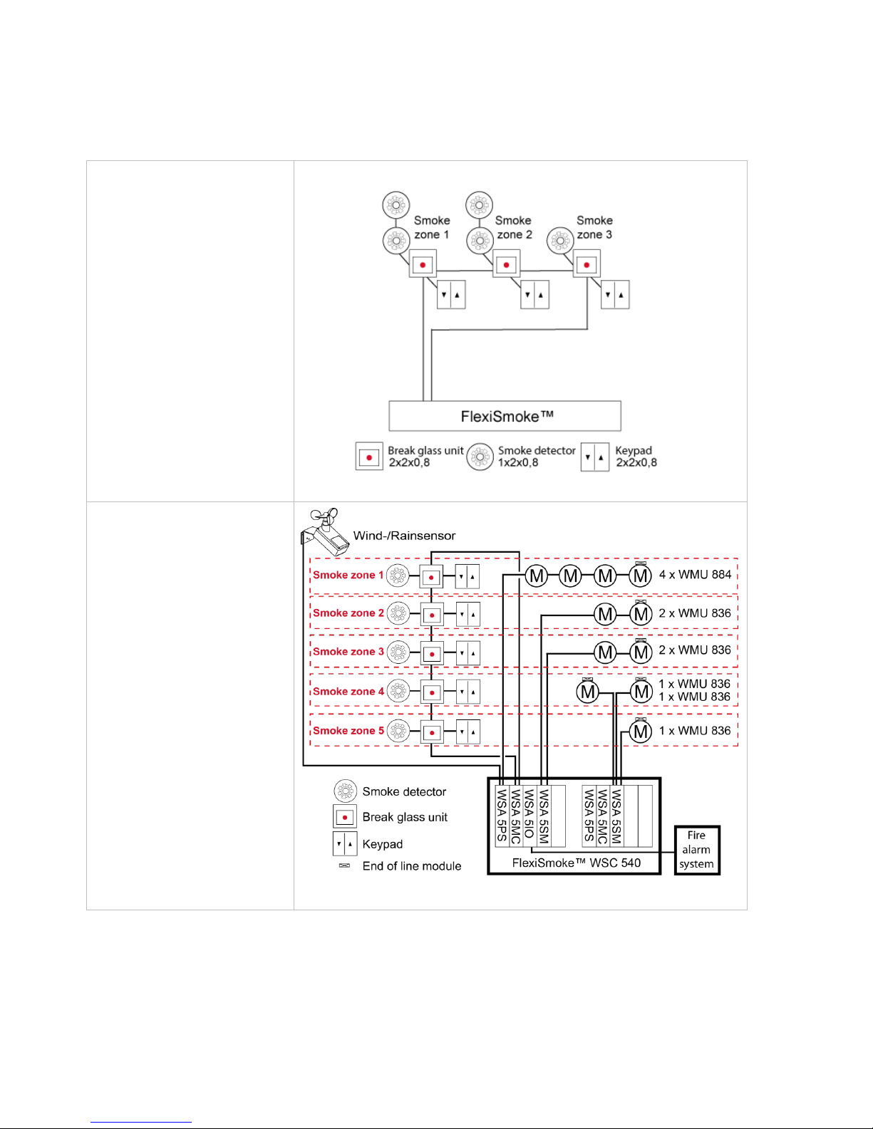
System example with
WSC 540
Smoke ventilation panel with
two sections (2 x 20A)
configured in five smoke zones.
Total ±24V standard motor
power consumption in the first
section is 20A (smoke zone 1- 2
- 3) and the total ±24V standard
motor power consumption in second section is 2A (smoke zone
4 - 5).
The keypads and break glass
units are cabled directly to the
break glass units type WSK
501/502 in the smoke zones
which mean that the need for
cabling in the building is
significantly reduced.
A wind/rain sensor is connected
to close the windows during
comfort ventilation in case of
high wind and/or rain.
The smoke ventilation panel is
connected to the Fire Alarm
System via the WSA 5IO
module.
Page 7
7
3 Variants of panels
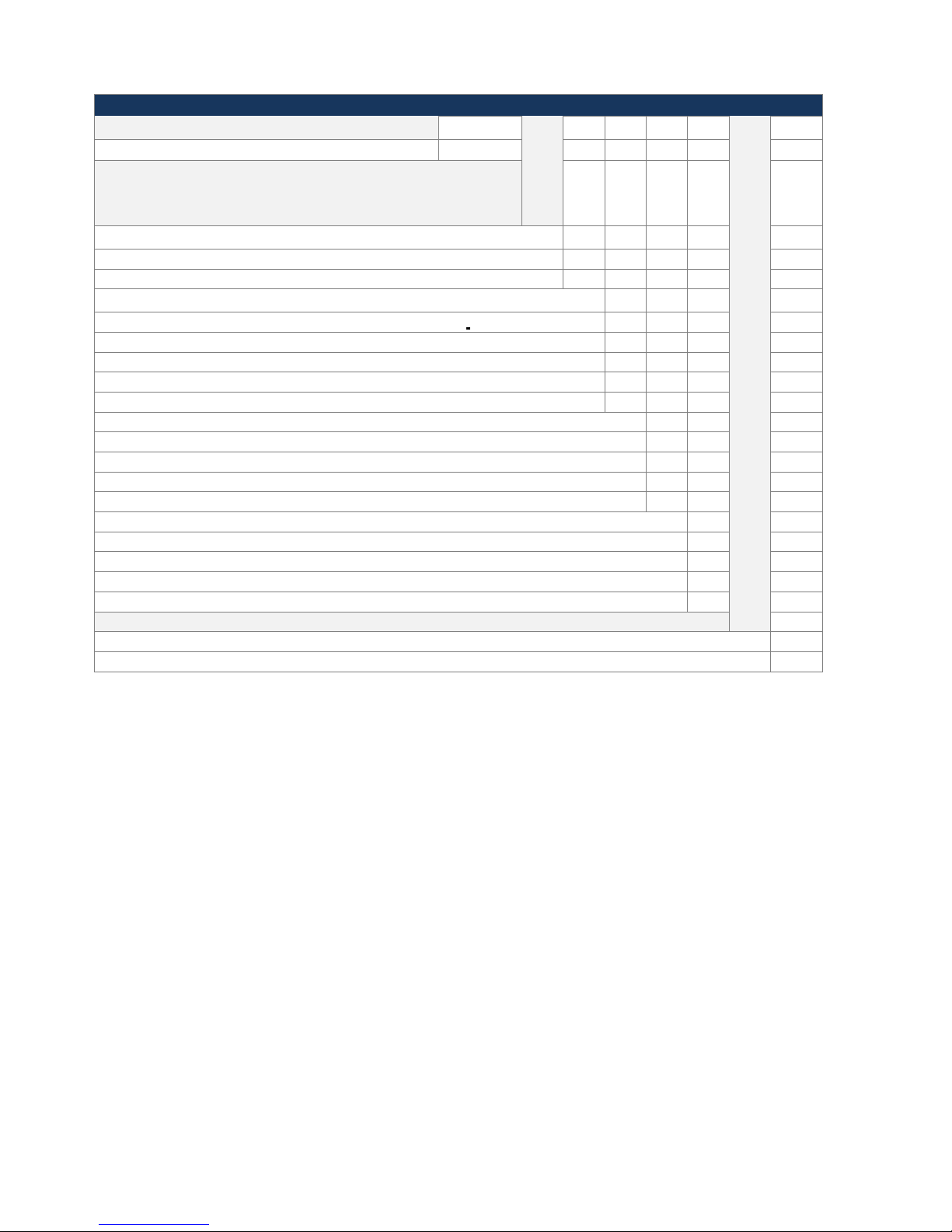
Item composing
Size of the smoke ventilation panel
WSC 5??
?
? ? ?
E1
20A = WSC 520, 40A = WSC 540, 60A = WSC 560
WSC 5??
Selection of modules
The four modules listed below must be defined for each 20A section -
WSC 520 has one section, WSC 540 has two sections and WSC 560
has three sections.
Select module: Overall control module
WSA 5MC NCO – without field bus interface
0
WSA 5MC KNX – with field bus interface for KNX/BACnet IP
K
Select modules: Expansion modules
First expansion module (slot 3, the first free slot in the section)
No module
0 WSA 5IO – input-/output-module *
I
WSA 5SM – motor module for ±24V standard motors
S
WSA 5ML – motor module for motors with MotorLink®
M Second expansion module (slot 4, the second free slot in the section)
No module
0
WSA 5IO – input-/output-module *
I
WSA 5SM – motor module for ±24V standard motors
S
WSA 5ML – motor module for motors with MotorLink®
M
Third expansion module (slot 5, the third free slot in the section)
No module
0
WSA 5IO – input-/output-module *
I WSA 5SM – motor module for ±24V standard motors
S WSA 5ML – motor module for motors with MotorLink®
M
Certification / Product version number
E = EN 12101-10
E
1 = product version number
1
* Module position
The IO module is inserted in slot 3 and if further IO modules are added, the IO module is inserted before the motor
module.
MotorLink® motor module is inserted before the ±24V Standard motor module.
Page 8
8
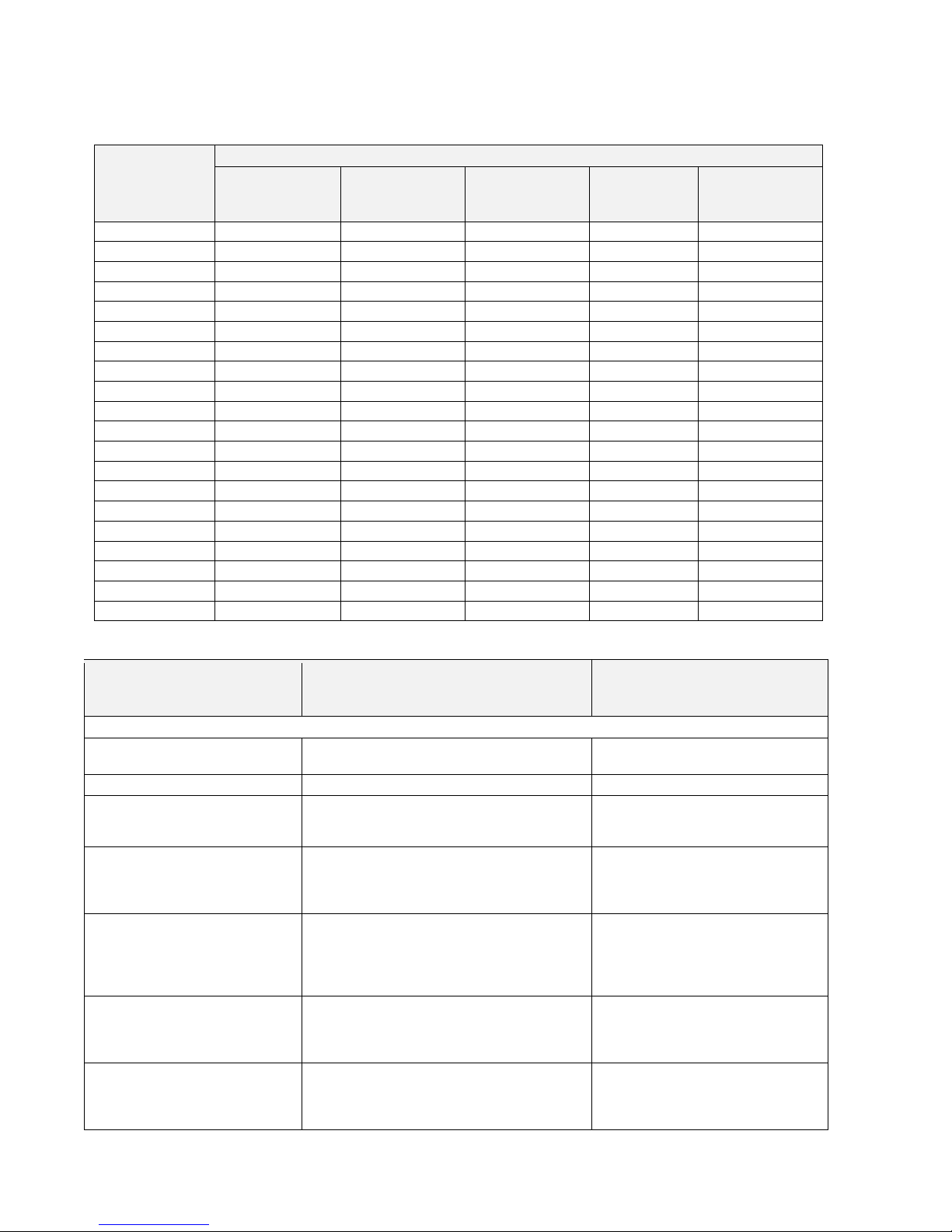
3.1 Number of motor lines, inputs and outputs depending on the
combination of the three expansion modules
The table shows the number of motor lines and inputs obtained per 20A section depending on the combination of the
expansion modules.
Combination
of expansion
modules
Number
Motor lines
±24V standard
Motor lines
MotorLink®
Inputs x 2
Outputs
(solid state)
Outputs
(relay)
(nc+no)
000 1 0 1 0
0
I00 1 0 4 3
1
S00 5 0 2 0 0 IS0 5 0 5 3 1 IIS 5 0 8 6
2
SS0 9 0 3 0
0
ISS 9 0 6 3 1 SSS
13
0
4 0 0
M00 1 4 2 0 0 IM0 1 4 5 3 1 IIM 1 4
8 6 2
MM0 1 8
3 0 0
IMM 1 8
6 3 1
MMM
1
12
4 0 0
MS0 5 4
3 0 0
IMS 5 4
6 3 1
MSS 9 4 4 0
0
MMS 5 8 4 0 0 II0 1 0
7 6 2
III
1
0
10 9 3
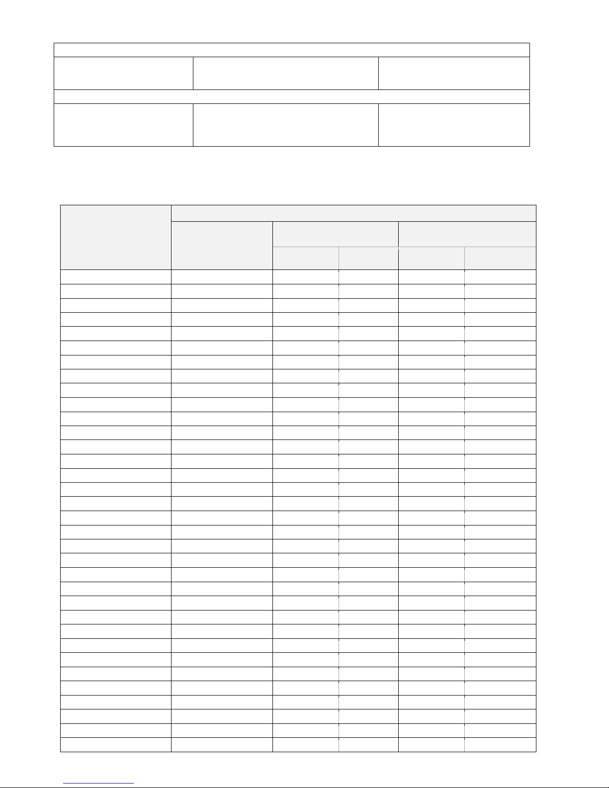
3.2 Examples with FlexiSmoke™
Number/type of motor
groups and other
functions
Expansion modules
Item number
Examples with WSC 520
1 ±24V standard motor line
no communication
no expansion modules
WSC 520 0000 E1
5 ±24V standard motor lines
1 x WSA 5SM 24V standard motor module
WSC 520 0S00 E1
5 ±24V standard motor lines
and KNX/BACnet IP field bus
interface
1 x WSA 5MC overall control module with
KNX/BACnet IP
1 x WSA 5SM 24V standard motor module
WSC 520 KS00 E1
5 ±24V standard motor lines,
KNX/BACnet IP field bus
interface and input / output
module
1 x WSA 5MC overall control module with
KNX/BACnet IP
1 x WSA 5IO input/output module,
1 x WSA 5SM 24V standard motor module
WSC 520 KIS0 E1
9 ±24V standard motor lines,
KNX/BACnet IP field bus
interface and input / output
module
1 x WSA 5MC overall control module with
KNX/BACnet IP
1 x WSA 5IO input/output module
2 x WSA 5SM 24V standard motor
modules
WSC 520 KISS E1
8 MotorLink® motor lines,
1 ±24V standard motor line
and KNX/BACnet IP field bus
interface
1 x WSA 5MC overall control module with
KNX/BACnet IP
2 x WSA 5ML MotorLink® motor modules
WSC 520 KMM0 E1
12 MotorLink® motor lines, 1
±24V standard motor line and
KNX/BACnet IP field bus
interface
1 x WSA 5MC overall control module with
KNX/BACnet IP
3 x WSA 5ML MotorLink® motor modules
WSC 520 KMMM E1
Page 9
9
Example with WSC 540
18 ±24V standard motor lines
2 x WSA 5IO input/output module
4 x WSA 5SM ±24V standard motor
modules
WSC 540 0ISS 0ISS E1
Example with WSC 560
20 MotorLink® motor lines, 3
±24V standard motor lines and
KNX/BACnet IP field bus
interface
3 x WSA 5MC overall control module with
KNX/BACnet IP
5 x WSA 5ML MotorLink® motor modules
WSC 560 KM00 KMM0 KMM0 E1
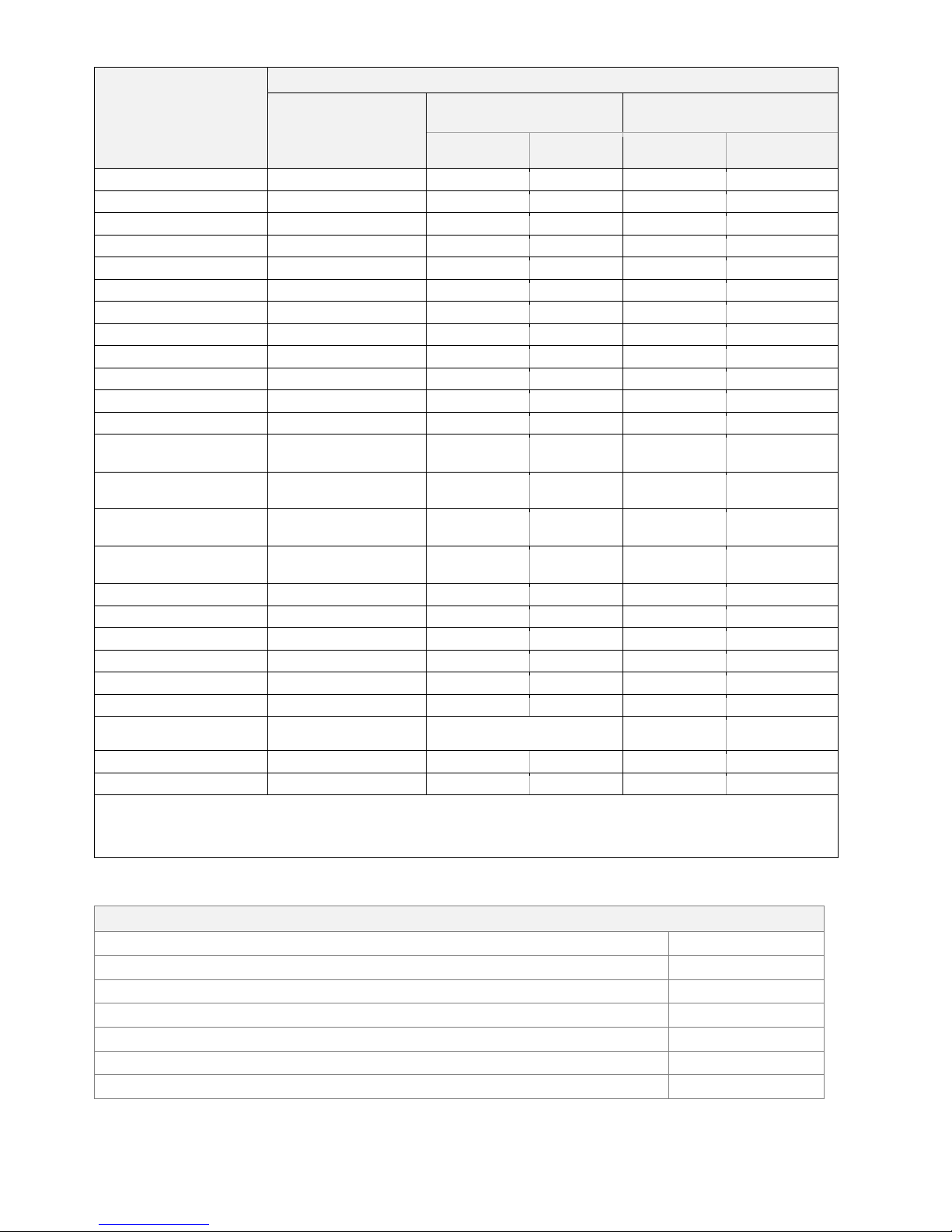
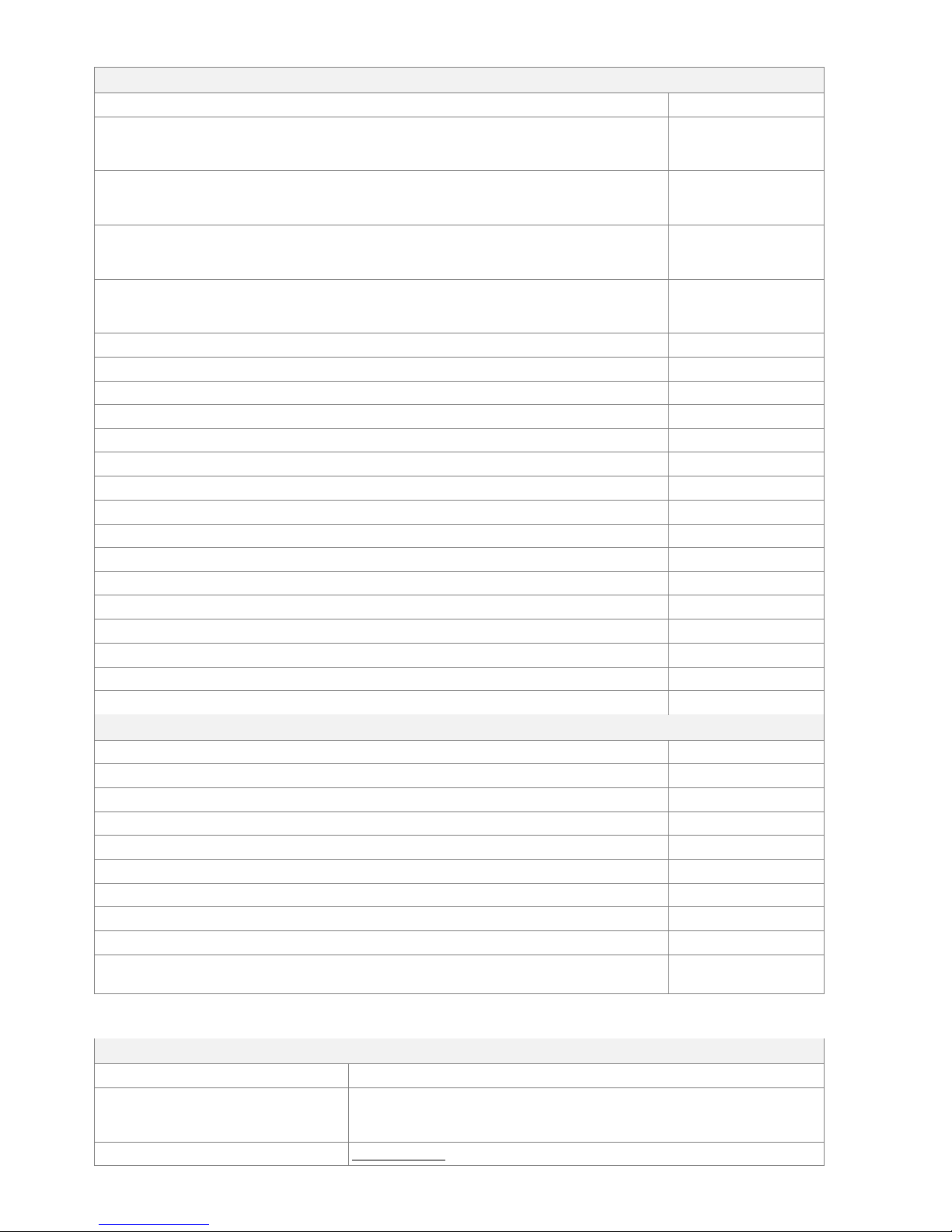
3.3 Max numbers of motors per motor line which can be connected per
module
The table shows the maximum number of motors that can be connected per motor line on one module depending on the type
of the module. The total power consumption of all the connected motors must not exceed 20A per section
Type of motor
Max. total 20A per section
WSA 5PS-module
1 x 20A-motor line
±24V
WSA 5SM-module
4 x 10A-motor lines ±24V
WSA 5ML-module
4 x 10A-motor lines MotorLink®
Motors per
motor line
Motors per
module
Motors per
motor line
Motors per
module
WMS 409 xxxx 01
10
5
10 0 0
WMS 409-1
10
5
10 4 16
WMS 409-2
10
4
10 2 8
WMS 409-3
9
3 9 3
12
WMS 409-4
8
4
10 4 16
WMS 515 4 2 4 0
0
WMU 831-1 / 851-1
20
10
20 4 16
WMU 831-2 / 851-2
20
10
20 2 8
WMU 831-3 / 851-3
18
9
18 3 12
WMU 831-4 / 851-4
20
8
20 4 16
WMU 836-1
20
10
20 4 16
WMU 836-2
20
10
20 2 8
WMU 836-3
18
9
18 3 12
WMU 836-4
20
8
20 4 16
WMU 852-1
9
4 9 4
9
WMU 852-2
8
4 8 2
8
WMU 852-3
9
3 9 3
9
WMU 852-4
8
4 8 4
8
WMU 861-1
13
6
13 4 13
WMU 861-2
12
6
12 2 8
WMU 861-3
12
6
12 3 12
WMU 861-4
12
4
12 4 12
WMU 862-1 / WMU 882-1
9
4 9 4
9
WMU 862-2 / WMU 882-2
8
4 8 2
8
WMU 862-3 / WMU 882-3
9
3 9 3
9
WMU 862-4 / WMU 882-4
8
4 8 4
8
WMU 863-1 / WMU 883-1
6
2 6 2
6
WMU 863-2 / WMU 883-2
6
2 6 2
6
WMU 863-3 / WMU 883-3
6
3 6 3
6
WMU 863-4 / WMU 883-4
4
0 0 0
0
WMU 864-1 / WMU 884-1
4
2 4 2
4
WMU 864-2 / WMU 884-2
4
2 4 2
4
WMU 864-3 / WMU 884-3
3
0 0 0
0
WMU 864-4 / WMU 884-4
4
0 0 0
0
Page 10
10
Type of motor
Max. total 20A per section
WSA 5PS-module
1 x 20A-motor line
±24V
WSA 5SM-module
4 x 10A-motor lines ±24V
WSA 5ML-module
4 x 10A-motor lines MotorLink®
Motors per
motor line
Motors per
module
Motors per
motor line
Motors per
module
WMU 885-1
4
2 4 2
4
WMU 885-2
4
2 4 2
4
WMU 885-3
3
0 0 0
0
WMU 885-4
4
0 0 0
0
WMU 895-1
4
2 4 2
4
WMU 895-2
4
2 4 2
4
WMU 895-3
3
0 0 0
0
WMU 895-4
4
0 0 0
0
WMX 503, 504, 523, 526-1
40
20
40 4 16
WMX 503, 504, 523, 526-2
40
20
40 2 8
WMX 503, 504, 523, 526-3
39
18
39 3 12
WMX 503, 504, 523, 526-4
40
20
40 4 16
WMX 803, 804, 813, 814,
823, 826-1
20
10
20 4 16
WMX 803, 804, 813, 814,
823, 826-2
20
10
20 2 8
WMX 803, 804, 813, 814,
823, 826-3
18
9
18 3 12
WMX 803, 804, 813, 814,
823, 826-4
20
8
20 4 16
WMD-1
20
10
20 4 16
WMD-2
20
10
20 2 8
WMD-3
18
9
18 3 12
WMD-4
20
8
20 4 16
WML 820/825
20
10
20 0 0
WML 860
20
10
20 4 16
WMB 801/802*
max. 4A connected to the
WMB
max. 4A connected to the WMB
0
0
WMB 811/812 */**
20
10
20
2
8
WMB 01M*/**
0
0
0
2
8
* Do not exceed the total power consumption of the motor line
** When having two locking motors per motor line, it must be one of each type: 1 x WMB 811 and 1 x WMB 812
*** The service input on the WMB 01M is ignored and can therefore not be used. When having two locking motors per motor line, it must be
one of each type: 1 x WMB 01M and 1 x WMB 02M.
4 Modules, accessories, spare parts
Modules
Power supply module 20A with 1 pcs. end of line module WSA 510
WSA 5PS
Overall control module without field bus interface
WSA 5MC NCO
Overall control module with field bus interface for KNX/BACnet-IP
WSA 5MC KNX
Input/output module
WSA 5IO
Motor module for ±24V standard motors with 4 pcs. end of line module WSA 510
WSA 5SM
Motor module for MotorLink® motors
WSA 5ML
Motor module for Renson® motors
WSA 5S5
Page 11
11
Accessories
Back-up battery 18Ah (2 x WSA 017 per 20A-section)
WSA 017
FlexiSmoke™ break glass unit, primary, with data communication, plastic housing. Optional
connection to ventilation keypad and smoke detector (only 1 per line).
(x=colour of the housing: 1=red, 2=yellow, 3=grey, 4=blue, 5=orange)
WSK 501 000x
FlexiSmoke™ break glass unit, primary, with data communication, metal housing. Optional
connection to ventilation keypad and smoke detector (only 1 per line).
(x=colour of the housing: 2=yellow, 3=grey, 5=orange)
WSK 502 000x
FlexiSmoke™ break glass unit, primary, with data communication, plastic housing. Not
possible to connect ventilation keypad and smoke detector.
(x=colour of the housing: 1=red, 2=yellow, 3=grey, 4=blue, 5=orange)
WSK 503 000x
FlexiSmoke™ break glass unit, primary, with data communication, metal housing. Not
possible to connect ventilation keypad and smoke detector.
(x=colour of the housing: 2=yellow, 3=grey, 5=orange)
WSK 504 000x
Fireman override switch
WSK 601
Smoke detector
WSA 300
Rain sensor
WLA 331
Rain/wind sensor
WLA 330
Rain/wind sensor, with pulse output
WLA 340
Wind speed sensor
WOW 201
Wind direction sensor
WOW 202
Bracket for junction box
WOW 203
Junction box for WOW 201 and WOW 202
WOW 204
End of line motor module, 10 pcs.
WSA 510
10kΩ resistance, 10 pcs.
WSA 501
Fire alarm system module
WSA 306
Cable for CAN connection, 2x2x0,5mm², sold in hole meters
WLL 501
Cable for wind and rain sensor WLA 340, 4m UV-resistant cable 4 x 2 x 0,75mm2
WLL 604
Cables for comfort ventilation – see separate data sheet for further information
WLL 7xx
Cables for smoke ventilation – see separate data sheet for further information
WLL 8xx
Spare parts
Touch screen for WSA 5PS module
WSA 5LD
Back plane for modules, with top and bottom plate
WSA 5BP
Micro SD card for FlexiSmoke™, special industrial grade
WSA 502
Safety lock incl. 2 keys for smoke ventilation panel housing
WSA 438
Spare key for smoke panel, 1 pcs.
WSA 439
Plugs: 2 pcs. 6-pin plugs for CAN bus and 2 pcs. 3-pin plugs for break glass units
WSA 540
Replacement glass for break glass units type WSK 501, 5 pcs.
WSK 397
Keys for break glass units type 501 / 503, 5 pcs.
WSK 398
Keys for break glass units type 502 / 504, 1 pcs.
WSK 453
Lockable replacement plastic housing for break glass unit
x=colour of the housing: 1 = red, 2 = yellow, 3 = grey, 4 = blue, 5 = orange
WSK 399 000x
5 Technical data
Technical data
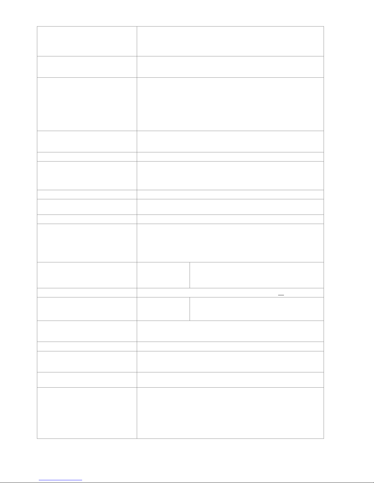
Output current (nominal)
WSC 520: 20A / WSC 540: 40A / WSC 560: 60A
Actuator secondary voltage
Motor voltage 24V DC (±15%)
Open circuit voltage at 230V AC (no load) 27.6V DC @ 20°
Ripple at max load max. 6% (3.5Vpp)
Motor lines
Per 20A section
Page 12
12
Motor groups
Smoke zones
max. 13 motor lines (1 x 20A ±24V standard motor line and 12 x ±24V
standard / MotorLink® motor lines) in max 13 motor groups and max 13
smoke zones
Via the software more motor lines can be connected in the same group
Primary voltage
WSC 520: 1 x 230V AC (±10%) / 50Hz
WSC 540: 2 x 230V AC (±10%) / 50Hz
WSC 560: 3 x 230V AC (±10%) (400V AC) / 50Hz
Power consumption
WSC 520: min 2.5W
1+2
, typ. 2.8W
1+3
. At max load 540W
WSC 540: min 5.0W
1+2
, typ. 5.6W
1+3
. At max load 1080W
WSC 560: min 7.5W
1+2
, typ. 8.4W
1+3
. At max load 1620W
1) no load: system operational but no motors are running
2) min: with 1 x break glass unit WSK 501/502 + 1 x smoke detector
WSA 300 per 20A section
3) max load: with 4 x break glass unit WSK 501/502 + 4 x smoke detector
WSA 300 per 20A section
Inrush current on primary site
WSC 520: 30A<0.05ms
WSC 540: 60A<0.05ms*), WSC 560: 90A<0.05ms*)
[*)= 30A < 0.05ms on each phase]
±24V change over time
min 500ms
Back-up batteries
(to be ordered separately)
WSC 520: 2 x WSA 017 (12V/17-18Ah)
WSC 540: 4 x WSA 017
WSC 560: 6 x WSA 017
Expected lifetime max 4 years, only use genuine WindowMaster batteries
Emergency power
>72 hours in accordance with EN 12101-10
Charging unit (integrated in WSA 5PS
module)
Charging voltage: 27.7 – 27.8 at 20ºC
Charging current: 3A, current limited
Priority
Smoke signal has always highest priority
Cable monitoring
±24V standard motors with end of line module and smoke detectors are
monitored by closed-circuit
Motors with MotorLink® and break glass units are monitored by data
communication
Back-up batteries are monitored by cyclic measuring
LED message OK, fault and alarm
Green
Yellow
Red
all OK
fault
fire
Reopening the actuators
Every 2.min. in 30min. after a SHE open (selectable) Preset: no reopening
Connection cable
Motors
Other
components
flexible max 6 mm² / solid max 10 mm²
min 0.2mm² / max 1.5mm², flexible stranded cores
are only suitable with attached ferrules
Operating conditions
-5°C - +40°C, max. 95% relative humidity (not condensing)
EN 12101-10: Operation class A, Environmental class 1, with IP value
increased to IP 54
Switch-on duration
ED 40% (4min. per 10min.)
Max allowed current drawn from the
battery when the primary power
source is disconnected
20.2A
Max interruption time during switching
between power sources
2.0sec
Break glass unit
Up to 30 break glass units type WSK 50x can be connected to the WSA
5MC module per 20A section. Up to10 smoke detectors can be connected
on 10 of these units type WSK 501/502, which give a maximum of 100
smoke detectors.
Ventilation keypads can also be connected to all the break glass units type
WSK 501/502 – there is no limit on the number of keypads.
Smoke detectors and ventilation keypads cannot be connected to the break
glass units type WSK 503/504.
Page 13
13
Number of motor lines per module
WSA 5PS
WSA 5SM
WSA 5ML
1x 20A motor line for ±24V standard motors
4 x 10A motor lines for ±24V standard motors
4 x 10A motor lines for MotorLink® motors
Note: A total of max 20A current consumption on
each 20A section of the smoke ventilation panel
Material
Metal housing for surface mounting
Colour
Grey (RAL 7035)
Size
WSC 520: 380 x 600 x 210mm (WxHxD)
WSC 540: 600 x 600 x 210mm
WSC 560: 1000 x 760 x 210mm
Weight
WSC 520: 17kg no batteries, 28kg with batteries (2 x WSA 017)
WSC 540: 26kg no batteries, 49kg with batteries (4 x WSA 017)
WSC 560: 57kg no batteries, 90kg with batteries (6 x WSA 017)
Protection class
IP54
Approval / certification
Approved and certified according to EN 12101-10
Delivery
FlexiSmoke™ smoke ventilation panel with WSA 501 (10kΩ resistors, 10
pcs.); WSC 520 x1, WSC 540 x2, WSC 560 x3 and 1 pcs. end of line
module WSA 510
Back-up batteries to be ordered separately.
To be ordered separately
Back-up battery WSA 017 (12V/17-18Ah) - order 2 batteries per 20A section
Note
We reserve the right to make technical changes
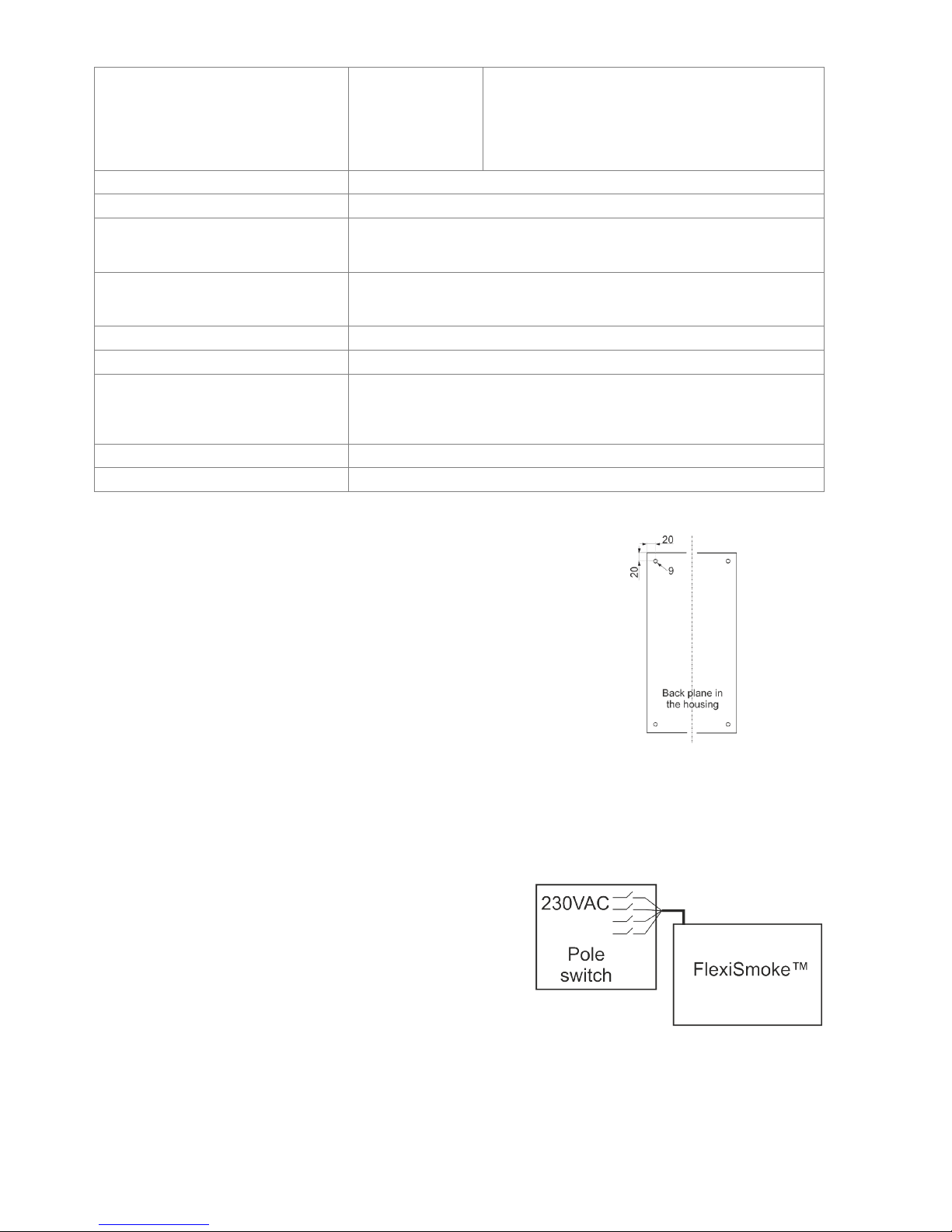
6 Mounting
The smoke ventilation panel is fixed to the wall through the Ø9mm holes in the
back plane of the housing.
If the panel is fixed in different way, the holes are to be blinded with the 4 blind
grommets, this way the IP class is maintained.
The door is turnable.
When turning the door also move the blind grommets to the new holes.
The smoke ventilation panel is to be located in a safe place, protected from the
effects of fire and smoke.
7 Installation
7.1 Cable routing
For cable routing we recommend the use of fire protected cables retaining their function E90 or E30.
See also chapter 8 “Cable dimensioning” in this instruction.
However, this has to be agreed with the Engineer or, if necessary, with the local fire protection department.
Do not reduce the cable cross sections specified in the cable lengths table. All cables of the control (except the mains supply
cable) carry 24V DC and have to be routed separate from the mains supply cable.
Adhere to the pertinent national and local regulations when routing
the cables.
Lead the connection cables into the housing of the control panel from
above and the cable glans shall comply with fire class V-1 (IEC/EN
60695-11-20 / UL 94) or higher.
Ensure that the mains cable can be switched via an external or
customer-supplied two-pole switch element or a switch element
controlling all poles – see drawing.
7.2 Cables into housing
All connection terminals (except the mains terminals) are of the plug-in type.
Connect the connection cables in accordance with the terminal plan. Ensure that the connections are made correctly.
Incorrect cable clamping, mixing up numbers or colours could lead to malfunctions of the control panel or of the external
components. Ensure that the electrical cables are always routed according to the valid national and local regulations.
Page 14

14
7.3 Connection of safety earth wire and 230V AC
See chapter 10 ‘Description of modules’, section 10.1, point X5 for further description.
7.4 Installation of the break glass unit, ventilation keypad and smoke
detector
Ensure that the break glass unit and the ventilation buttons are visible and well accessible.
Do not install behind protruding walls, door panels or hidden by the building structure.
Note: Installation height of the break glass unit 1.5 – 1,7m above floor.
Install the smoke detectors in accordance with their enclosed instructions
7.5 Assembly instructions
Always have assembly, installation, repair and maintenance of smoke and heat extraction systems carried out by
qualified personnel trained for this purpose.
Rules to be adhered to for setting up and installation
The following safety relevant rules have to be adhered to when planning the use of a smoke and heat extraction system
and its set-up and installation:
• The Provincial Building Ordinance of the provinces,
• The regulations of the competent fire protection authority,
Accident prevention regulations
Adhere to the general accident prevention regulations (APR), the APR for power operated windows and doors, and the
installation rules in your country.
CAUTION:
Live components are directly accessible after opening the system housing.
Prior to inserting / removing modules disconnect to the panel from the mains supply and the back-up batteries.
• adhere to the installation instructions and your local energy providers
• select the place of installation such that free access is guaranteed for maintenance purposes
• select cables according to regulations in this instruction - take the calculation of the motor supply cable lengths
into account when laying the cables
• power cables entered via the cable glands
• connect the cables in accordance with the drawings provided by the manufacturer
• route the cables in the building according to the regulations in this instruction
• after the smoke panel is installed the back-up batteries will be fully charged after ca. 8 hours
• check all system functions
Electric cable routing for smoke and heat extraction systems
Electrical cables always have to be laid in accordance with the national and local rules in your country.
Do not use the PE wire / green/yellow wire!
Cables of type NYM, concealed, can be used.
For surface laying, halogen free safety cables are recommended (see cable plan).
If possible, the use of cable types should be agreed with the Technical Services and the competent fire protection
authority.
For the maximum permissible cable lengths of the motor supply cables for the WSC 5XX system, taking the specified
cable cross sections into account (cable information for surface laying), please refer to chapter 8 “Cable dimensioning”.
8 Cable dimensioning
8.1 Maintaining the cable functions
According to valid national regulations.
The cable network for smoke ventilation systems (“Cable system“) ends normally at the interface (junction box) for the
actuator!
The flexible, heat resistant connection cable of actuator is part of the system component‚ electric motor actuation' and is
not a part of the electrical installation!
We recommend in all cases to discuss the type of cable routing with the competent fire fighting authorities.
8.2 Formula for the calculation of the maximum motor cable length
Max. cable length = permissible voltage drop 2V (UL) x conductivity of copper(56) x cable cross section in mm2 (a)
max. motor current total in amps (I) x 2
Example
Max motor cable length with cable cross section 0.75mm2 and actuator current 2A: (2 x 56x0.75) : (2 x 2) = 21m
Maximum motor cable length
Always routed from the central smoke control
unit to the last junction box
Permissible max. voltage drop in the line
2 Volt
When 5 wire cable and MotorLink®
Page 15
15
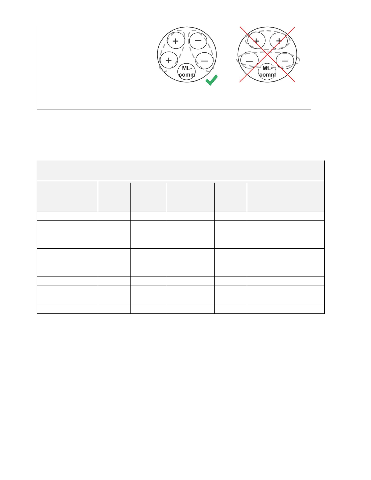
Actuating current: Sum of all motor power
consumption per motor line
The motor supply cable must have 3 wires: 2
wires current carrying /1 wire for monitoring.
Note: do not use the PE wire /
green/yellow wire!
ML-comm = MotorLink® communication.
It is not recommended to use parallel-wire.
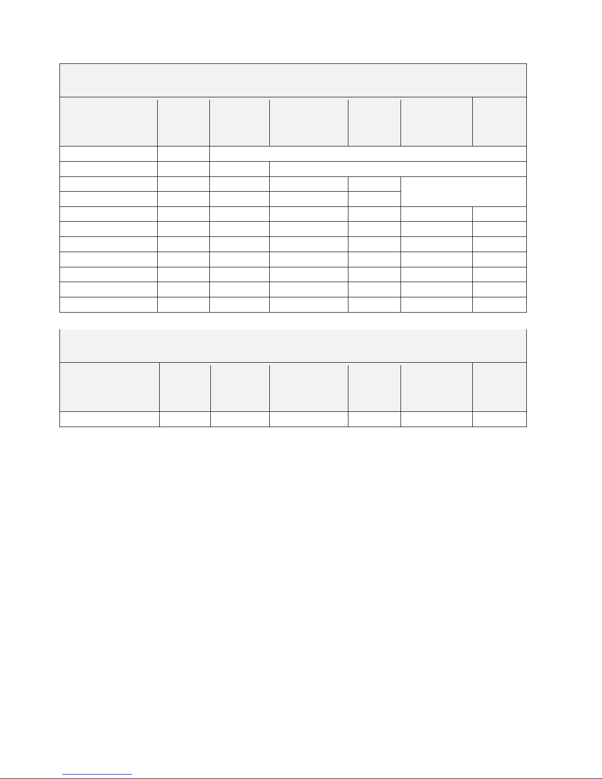
8.3 Max. cable Length
Maximum permissible cable length from the smoke ventilation panel to the motors and pyrotechnic gas generator taking
into account the cable cross-section is shown in the following tables for “± 24V standard motors“, “MotorLink® motors“ and
pyrotechnic gas generator.
8.3.1 Max cable length – ±24V standard motors
Before selecting the cable type, please see X1-X4 in section WSA 5SM Standard motor module.
±24V standard motors
Do not use the PE wire / green/yellow wire!
cable cross
section [a]
Total
actuator current [I]
3 wire *
0.75mm²
3 wire *
1.50 mm²
5 wire *
1.50 mm²
2 wire parallel
3 wire *
2.50 mm²
5 wire *
2.50 mm²
2 wire parallel
3 wire
4.00 mm²
1A
42m
84m
168m
140m
280m
224m
2A
21m
42m
84m
70m
140m
112m
3A
14m
28m
56m
47m
93m
75m
4A
11m
21m
42m
35m
70m
56m
5A
8m
17m
34m
28m
56m
45m
6A
7m
14m
28m
23m
47m
37m
7A
6m
12m
24m
20m
40m
32m
8A
5m
11m
21m
18m
35m
28m
9A
9m
18m
15m
31m
25m
10A
8m
16m
14m
28m
22m
20A
4m
8m
7m
14m
11m
Page 16
16
8.3.2 Max cable length – motors with MotorLink
®
Before selecting the cable type, please see X1-X4 in section WSA 5ML Standard motor module.
Motors with MotorLink®
Do not use the PE wire / green/yellow wire!
cable cross
section [a]
Total
actuator current [I]
3 wire *
0.75mm²
3 wire *
1.50 mm²
5 wire *
1.50 mm²
2 wire parallel
3 wire *
2.50 mm²
5 wire *
2.50 mm²
2 wire parallel
3 wire *
4.00 mm²
1A
42m
50m
2A
21m
40m
50m
3A
14m
28m
50m
47m
50m
4A
11m
21m
42m
35m
5A
8m
17m
34m
28m
50m
45m
6A
7m
14m
28m
23m
47m
37m
7A
6m
12m
24m
20m
40m
32m
8A
5m
11m
21m
18m
35m
28m
9A
9m
18m
15m
31m
25m
10A
8m
16m
14m
28m
22m
20A
4m
8m
7m
14m
11m
8.3.3 Max cable length – Pyrotechnic gas generator
Pyrotechnic gas generator**
Do not use the PE wire / green/yellow wire!
cable cross
section [a]
Total
actuator current [I]
3 wire *
0.75mm²
3 wire *
1.50 mm²
5 wire
1.50 mm²
2 wire parallel
3 wire *
2.50 mm²
5 wire
2.50 mm²
2 wire parallel*
3 wire *
4.00 mm²
1A
42m
84m
168m
140m
280m
224m
* flexible stranded cores are only suitable with attached ferrules. Max 1 core / ferrule per terminal.
**FlexiSmoke™ has been tested with Chemring type 1.3.
Page 17
17
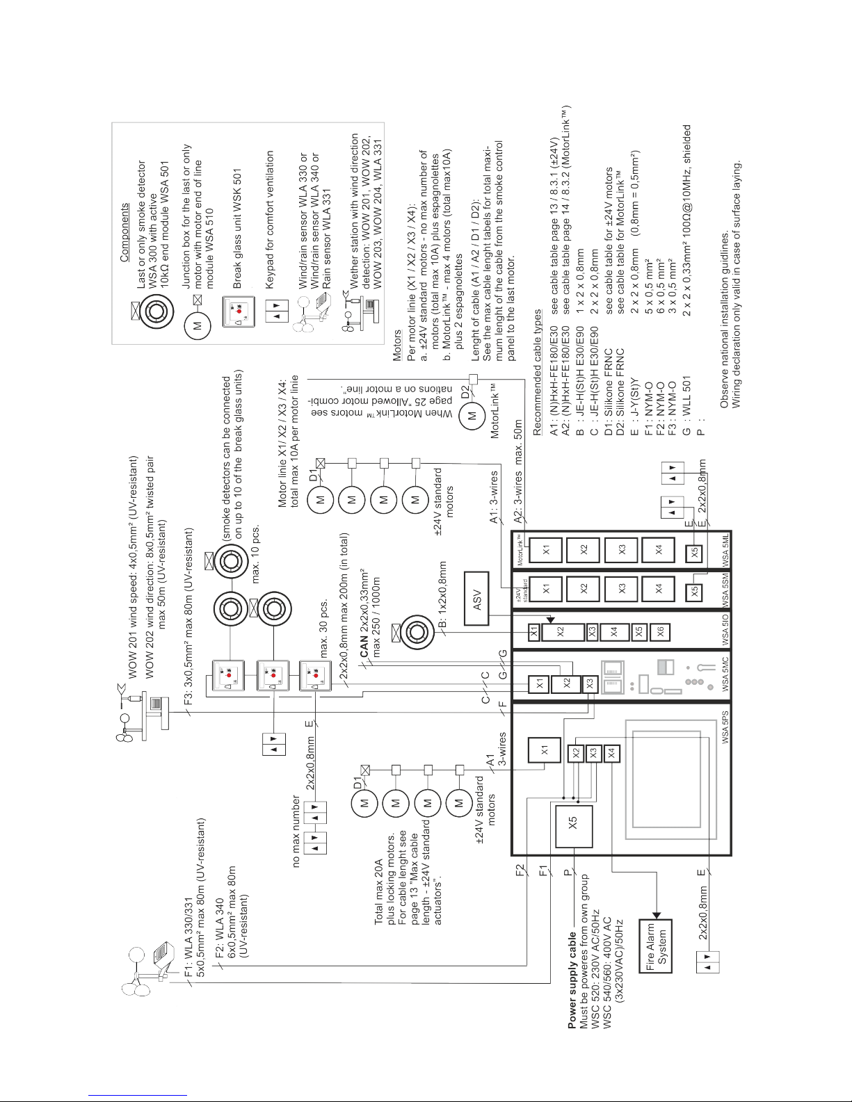
9 Cable plan for connection to WSC 520 / WSC 540 / WSC 560
Page 18
18
10 Description of modules
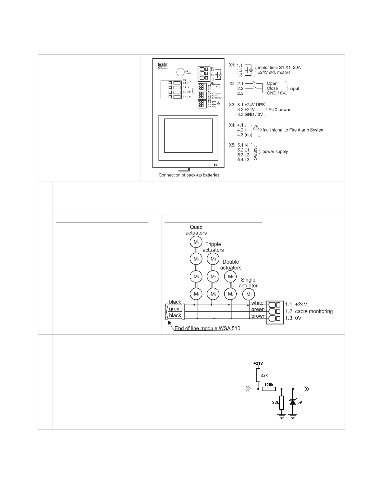
10.1 WSA 5PS power supply module 20A
Each 20A section has a WSA 5PS
power supply module.
The module contains:
- one motor line (S1 X1) for ±24V
standard motors
- two free configurable inputs for
connection of e.g. wind/rain sensor
WLA 330 or keypad for comfort
ventilation
- one output for additional power
supply to sensors
- output for fault signal
- connection of power supply
- touch screen for configuration,
commissioning and maintenance
X1
For connection of ±24V standard motors (total max 20A) and espagnolette actuators type
WMB 801/WMB 802/811/812.
All motors on motor line ‘S1 X1’ will run/be operated simultaneously.
Connection / cable diameter: flexible max 6 mm² / solid max 10 mm².
Cable length: see the chapter "Cable Sizing".
Examples with 20A power consumption
a) 20 pcs. WMX 824-1
b) 10 sets of 2 pcs. WMX 824-2
c) 4 pcs. WMU 885-1
d) 2 sets of 2 pcs. WMU 885-2
Connection of motors on motor line S1 X1
X2
For connection of wind/rain sensor type WLA 330 or WLA 340, rain sensor WLA 331, keypad, Fire Alarm System etc.
For wind direction depending SHE - see chapter 10.2, section X3.
Data
2.1 Input
2.2 Input
2.3 GND / 0V
With the default values are input:
”Active” if the contact resistance is smaller than 4kΩ
”Inactive” if the contact resistance is bigger than 8kΩ.
For values between 4 and 8kΩ the result will depend on the supply voltage.
Input has pull up approx. 1mA. (min 0.7mA, max 1.4mA )
Input threshold is defaulted to ”1200” equal to 6.2V, given at approx. 6kΩ.
The threshold can be set in the interval 0..4095 bit, approx. 5.2mV/bit
Input circuit (simplified)
Page 19
19
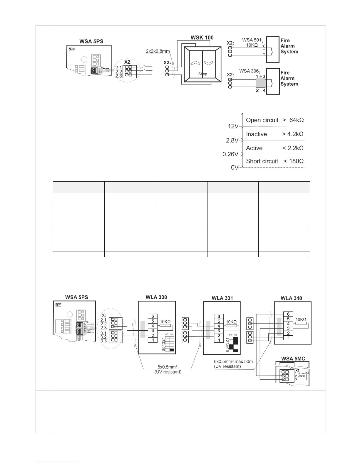
Example 1: Keypad and Fire Alarm System
Use of cable monitoring e.g. from Fire Alarm System
If cable monitoring is not used, the input has only one threshold (G1).
If the input voltage is above this threshold it is inactive.
If the input voltage is under this threshold it is active.
Cable monitoring type "2"
Type "2" is used in conjunction with WSA 306.
This type of cable monitoring is the most secure because it detects
both interruption and short circuit.
Limit values 2.8V, 0.26V and 12V are used.
Cable monitoring Type "1"
Type "1" is used with WSA 501.
This kind of cable monitoring detects only interruption.
Limit values 2.8V and 12V are used.
Threshold
configuration
Short circuit
Active
Inactive (*)
Open circuit
Switch
(no monitoring)
-
< 2.8V (<2.2kΩ)
> 2.8V (>4.2kΩ)
Type 1:
Cable
monitoring with
WSA 501
-
< 2.8V (<2.2kΩ)
> 2.8V (>4.2kΩ)
> 12V (> 64kΩ)
Type 2:
Cable
monitoring with
WSA 306
< 0.26V (<
0.18kΩ)
< 2.8V (<2.2kΩ)
> 2.8V (>4.2kΩ)
> 12V (> 64kΩ)
Manual
0V - 22V
0V - 22V
0V - 22V
Resistance values based on 18V to 30V supply voltage
(*) Not configurable
Example 2: Wind/rain and rain sensors
WLA 330 and WLA 331– the settings of the sensors are set on the sensor.
WLA 340 – the settings of the sensor are programmable on the smoke panels touch screen.
X3
Additional power supply for sensors etc.
3.1 min. 18V max. 29V additional power supply with back-up batteries, max current consumption 50mA
3.2 min. 18V max. 29V additional power supply without back-up batteries, max current consumption 200mA
3.3 GND / 0V
Only use additional power supply with additional power supply (X3.1) if really necessary, as this will influent on the life
time of the back-up battery.
Page 20
20
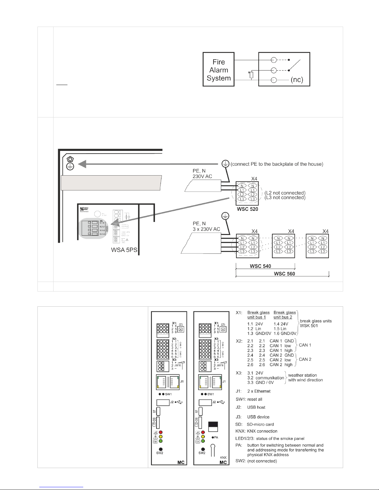
*
X4
Solid state output for transmission of fault
signal.
Closed contact = OK
Open contact = Fault
A fault must last a minium of 20 seconds befoe
the relay indicate a fault.
Data
Max voltage: 30 Vp (peak)
Max output: 150 mA
Typical On-resistance: 4.7 Ω
Max On-resistance: 8 Ω
Max switching speed: 2 ms
*depends on the fire alarm system cable surveillance
X5
Connection of power supply:
WSC 520: 230V AC
WSC 540: 2x230V AC, cables are connected in the first 20A section
WSC 560: 3x230V AC, cables are connected in the first 20A section
F1
Fuse 3.15A slow
10.2 WSA 5MC overall control module
Each 20A section contains an overall
control module WSA 5MC.
The module is available with or without
field bus interface for KNX.
The module can contain i.e.:
- input for break glass unit type
WSK 50x
- CAN bus interface for connection of
more smoke ventilation panels
- connection of weather station with wind
direction detection
- LEDs for status of the smoke ventilation
panel
- connection for field bus for KNX (only
modules with communication)
Page 21
21
X1
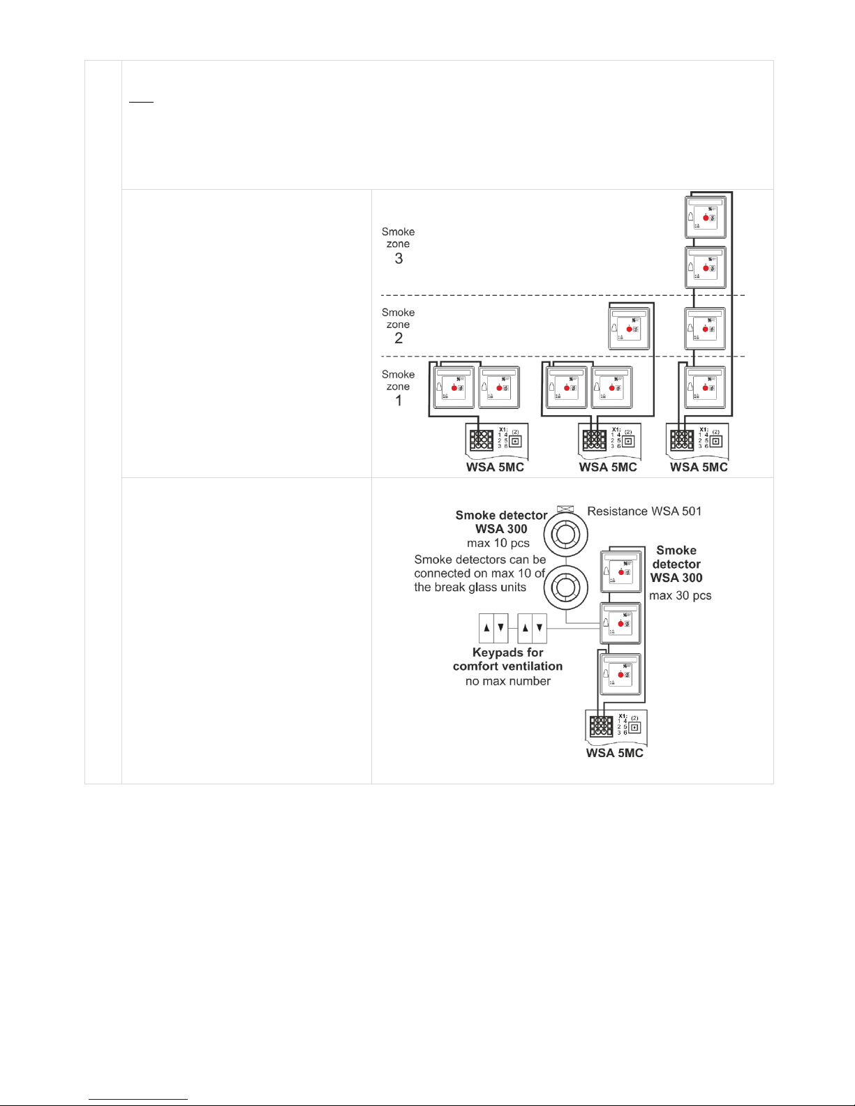
For connection of break glass unit type WSK 50x.
Data
Break glass unit bus 1 Break glass unit bus 2
1.1 24V 1.4 24V
1.2 LIN1 (communication) 1.5 LIN2 (communication)
1.3 LIN1 GND / 0V 1.6 LIN2 GND / 0V
Imax = 64mA when 30 break glass units and 100 smoke detectors.
As the break glass units are monitored,
the connection of the break glass units
depends therefore of the number of
smoke zones.
The break glass units can always be
connected in a ring but must, as a
minimum:
- when 1 smoke zone - connect to break
glass unit bus 1
- when 2 smoke zones - connect to
break glass unit bus 1 respectively to
break glass unit bus 2
- when 3 or more smoke zones connect in ring
Smoke detectors and keypads are
connected on the break glass unit type
WSK 501/502.
Per 20A section up to 30 break glass
units can be connected.
On max 10 of these 30 break glass units
smoke detectors type WSA 300 can be
connected - and max 10 smoke
detectors per break glass unit.
This gives a total of 100 smoke detectors
per 20A section.
Page 22
22
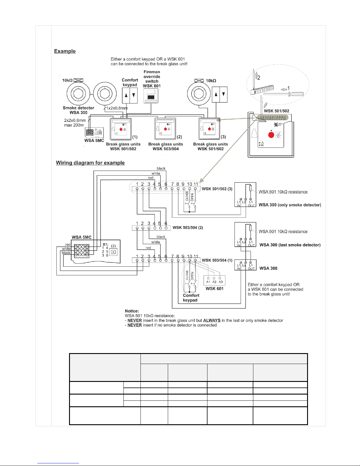
Example:
3 smoke zones and connected components; 2 break glass units WSK 501/502, 1 break glass unit type WSK 503/504,
3 smoke detectors WSA 300, 2 resistances WSA 501, 1 fireman override switch WSK 601 and 2 ventilation keypads.
See chapter 9 "Cable plan for connection to WSC 5xx" for cable types and lengths.
Connection of different types of smoke detectors to FlexiSmoke™
Smoke detector type
WSA 300
Hekatron
MSD 523
(max 5 pcs)
Hekatron
SSD 521/a
(WSA 200 6101)
Apollo, Orbis
ORB-OH-13001-AP0
ORB-OP-12001-AP0
Connect to WSA 5IO
X1,1
L1 In 2 2
In +
X1,2
L2 1 1
Com -
Connect to WSK
p 7
L2 1 1
Com -
p 8
L1 In 2 2
In +
ALWAYS connect 10 KOhm
in between
L2
and
L1 Out
1
and
3
1
and
3
Com –
and
Out +
Page 23
23
X2
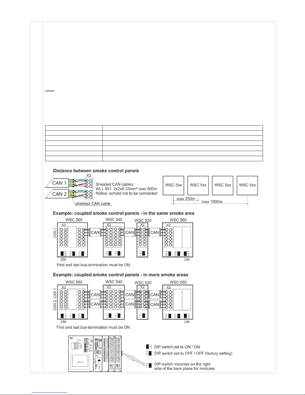
More FlexiSmoke™ smoke ventilation panels can be connected together via X2.
It is possible to connect up to 31 20A-sections
The smoke panels are coupled via X2 in the last 20A section in panel x to the first 20A section in panel x+1. See
Section 9 "Cable plan for connection to WSC 5xx" and drawing below. The CAN cable between two smoke ventilation
panels must not exceed 250m and the total cable length must not exceed 1000m.
When the panels are mounted in the same smoke zone the panels are connected via CAN1.
If the panels are mounted in two or more smoke zones the panels are connected via CAN1 and CAN2 in separate
cables.
A red DIP switch is mounted on the back plane for the modules. Factory setting is set to OFF.
When connection more panels the switch on the first 20A section in the first panel and the switch on the last 20A
section in the last section are to be set to ON.
Data
2.1 CAN1 GND
2.2 CAN1 L
2.3 CAN1 H
2.4 CAN2 GND
2.5 CAN2 L
2.6 CAN2 H
Communication:
closed CAN 2.0B network
Data speed:
10 kb/s
Coupling:
shielded CAN cable (e.g. cable type WLL 501, see accessories list)
Isolation:
galvanic separated
Cable impedance:
100Ω at 10MHz
Termination resistance:
120Ω (see below example with DIP-switch settings)
Cable dimension:
2 x 2 x 0.33mm2
Page 24
24
X3
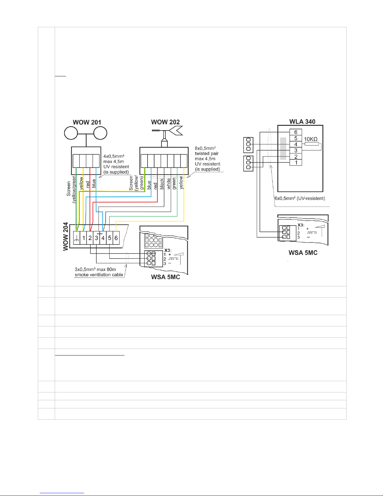
For connection of intelligent weather station (wind direction dependent smoke and heat extraction).
The type of weather station is configured on the touch screen and can for example consist of:
WOW 201 (wind speed), WOW 202 (wind direction), WOW 204 (junction box), WOW 203 (bracket for junction box) or
WLA 340 (wind speed and rain sensor).
The weather station can also be equipped with a pole and wall bracket for pole (not delivered by WindowMaster).
Data
3.1 Min 18V max 29V (depends on the mode of operation: mains / back-up batteries). Imax = 8mA
3.2 Communication
3.3 GND / 0V
As the weather station is monitored by both communication and time out (wind without time), any cable errors will be
registered.
J1
Ethernet connection to remote configuration and BACnet IP communication *
SW1
Restart all.
When activating SW1 the WSC 5MC in the current section will be restarted (configuration will not be lost). *
J2
USB host. Used to store configurations in USB stick.(prepared for later expansions) *
J3
USB device (prepared for later expansions) *
SD
SD-Micro card slot. * Used for log file and back up of the configuration of the panel. The card should NOT be removed.
LED
Shows the status of the panel
Red = alarm
Yellow = fault
Green fast flickering = all OK (CPU working), Green constant = CPU communication stopped (possible reset or contact
WindowMaster)
KNX
Connection of KNX communication bus (only on the WSA 5MC KNX module) *
PA
KNX button for switching between normal KNX operation and addressing mode (KNX)
SW2
Contact without function (prepared for later expansions)
*
J1, SW1, J2, J3, SD, KNX: When operated on back-up batteries these functions are closed down
Page 25
25
10.3 WSA 5IO input/output module
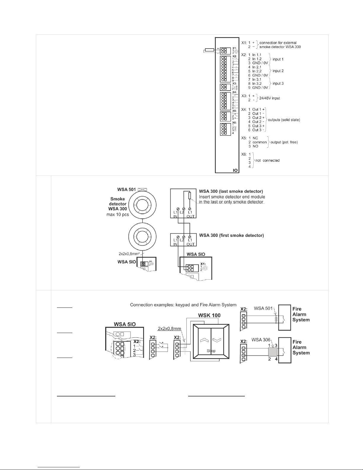
The WSA 5IO module contains:
Inputs
- 1 connection for external smoke detector when no break
glass unit is connected
- 3 free configurable inputs for connection of e.g. keypads for
comfort ventilation or inputs from Fire Alarm System
- 1 24/48V Fire Alarm System – primarily used in France
Outputs
- 3 free configurable solid state outputs
- 1 free configurable potential free output for
connection to e.g. Fire Alarm System or other systems
X1
For connection of smoke detector type WSA 300.
Imax = 3.4mA
For connection of a different type smoke detector, see the example in section 10.2
X2
Three times two free configurable inputs.
Input 1
2.1 input 1.1
2.2 input 1.2
2.3 GND 1 / 0V
Input 2
2.4 input 2.1
2.5 input 2.2
2.6 GND 2 / 0V
Input 3
2.7 input 3.1
2.8 input 3.2
2.9 GND 3 / 0V
Fire Alarm System shown with cable monitoring type 1 and type 2:
Cable monitoring Type "1"
Type "1" is used with WSA 501.
This kind of cable monitoring detects only
interruption.
Cable monitoring type "2"
Type "2" is used in conjunction with WSA 306.
This type of cable monitoring is the most secure
because it detects both interruption and short circuit.
See Chapter 10, Section 10.1, point X2 for detailed explanation about input options, cable monitoring, etc.
Page 26
26
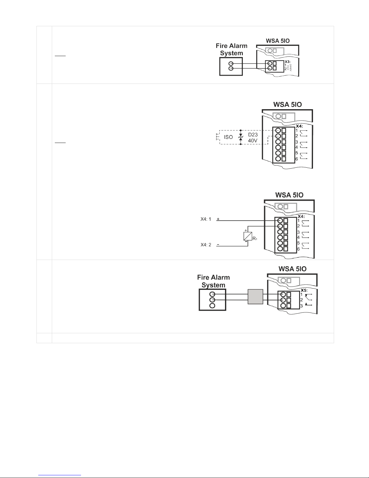
X3
24/48V free configurable input from e.g. Fire Alarm
System
(used primarily in France).
Data
Active at voltages between 18 and 50V
Passive below 1V
Max.50V
Connection example
X4
3 free configurable solid state outputs
4.1 Output 1
4.2 Output 1
4.3 Output 2
4.4 Output 2
4.5 Output 3
4.6 Output 3
Data
Max voltage: 30 Vp (peak)
Max current: 150 mA
Typical On-resistance: 4.7 Ω
Max On-resistance: 8 Ω
Max switching speed: 2 ms, only for DC-voltage
Output circuit (simplified)
Example with solid state and relay
X5
Free configurable potential free output.
Free configurable potential free relay output for
connection of e.g. Fire Alarm System or siren.
5.1 NC = normally closed
5.2 Commen
5.3 NO = normally open
Max DC voltage : 30 Volt
Max AC voltage : 100 Volt
Max current: 1A
Remember cable monitoring
– see the Fire Alarm System
X6
Not used
Page 27
27
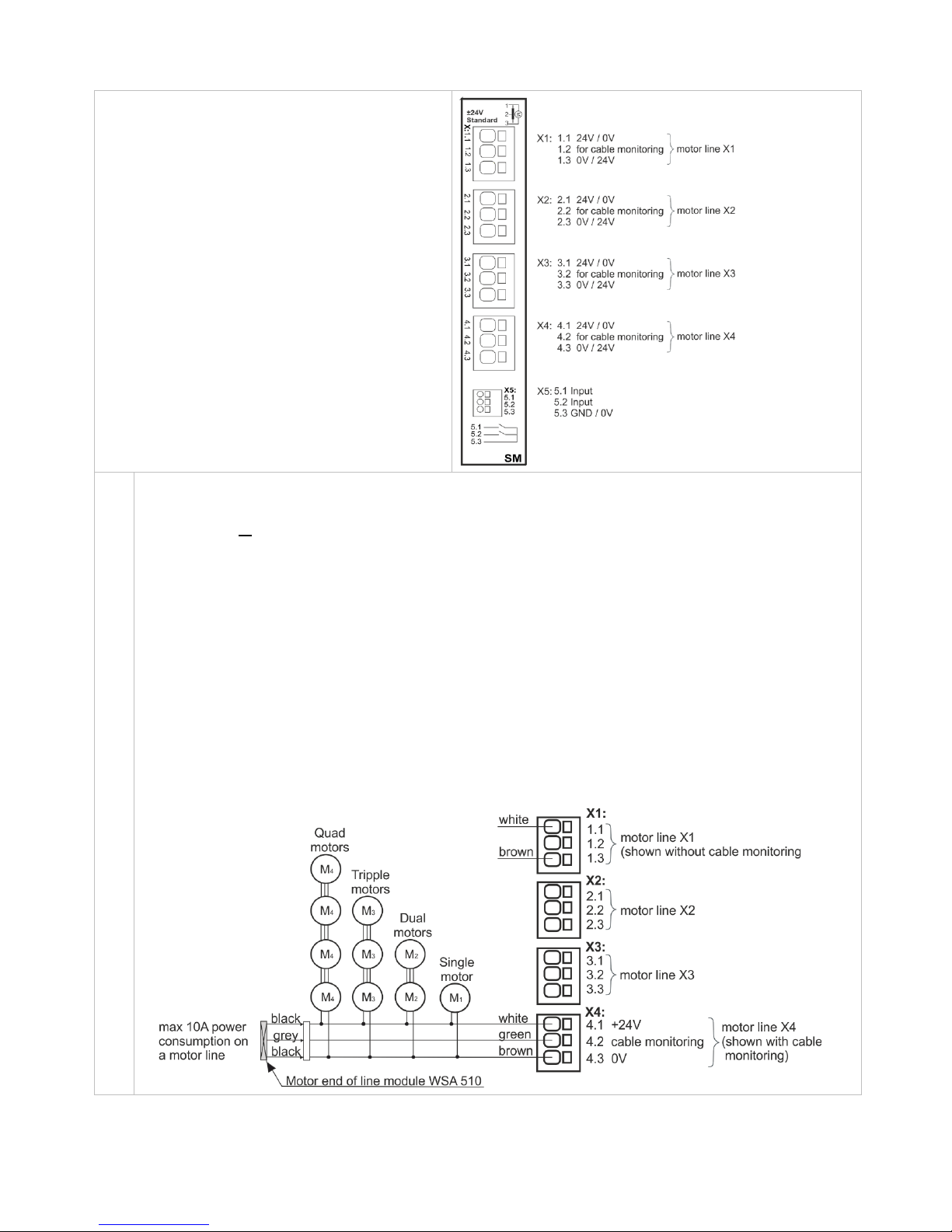
10.4 WSA 5SM standard motor module
WSA 5SM motor module provides:
- 4 motor lines for ±24V standard motors
- 1 x 2 free configurable inputs for connection of e.g.
keypad or wind/rain sensor
X1
X2
X3
X4
Motor line X1, X2, X3 and X4
The WSA 5SM module has four motor lines (X1, X2, X3 and X4) for connection of ±24V standard motors.
On each motor line motors with a total power consumption of max. 10A can be connected; however the total max power
consumption for all four motor lines must not exceed 20A.
Besides motors also locking motors (espagnolette motors) type WMB 801, WMB 802, WMB 811 and WMB 812 can be
connected. The power consumption of the locking motors are not to be included in the 20A as motors and locking
motors do not run at the same time.
All motors on the same motor line will drive/be operated simultaneously.
For cable length se chapter “Cable dimensioning”.
Cable diameter: flexible max 6mm², solid 10mm. Flexible stranded cores are only suitable with attached ferrules. Max 1
core / ferrule per terminal.
If cable monitoring is wanted a “Motor end of line module” type WSA 510 is to be added. When using non-
WindowMaster the cable monitoring is set to “simple”, see section 11.1”.
Examples with max 20A power consumption:
a) 2 sets of 10 pcs. WMX 826-1
b) 2 sets of 5x2 pcs. WMX 826-2
c) 4 pcs. WMU 885-1
d) 2 sets of 2 pcs. WMU 885-2
Page 28
28
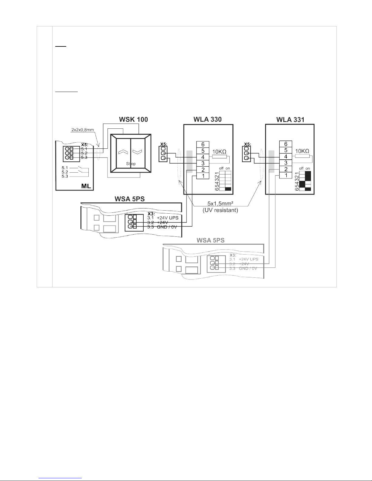
X5
Potential free connection for e.g. keypads, wind/rain sensor or rain sensor, if they are not connected on the WSA 5PS
module. Connection for power supply for the wind/rain or rain sensors are still at WSA 3PS X3.
Data
Cable diameter: max 1.5 mm²
5.1 Input
5.2 Input
5.3 GND / 0V
See Chapter 10, Section 10.1, point X2 for detailed description about input options, cable monitoring etc.
Examples
- WSK 100 keypad for comfort ventilation
- WLA 330 wind/rain sensor
- WLA 331 rain sensor
Page 29
29
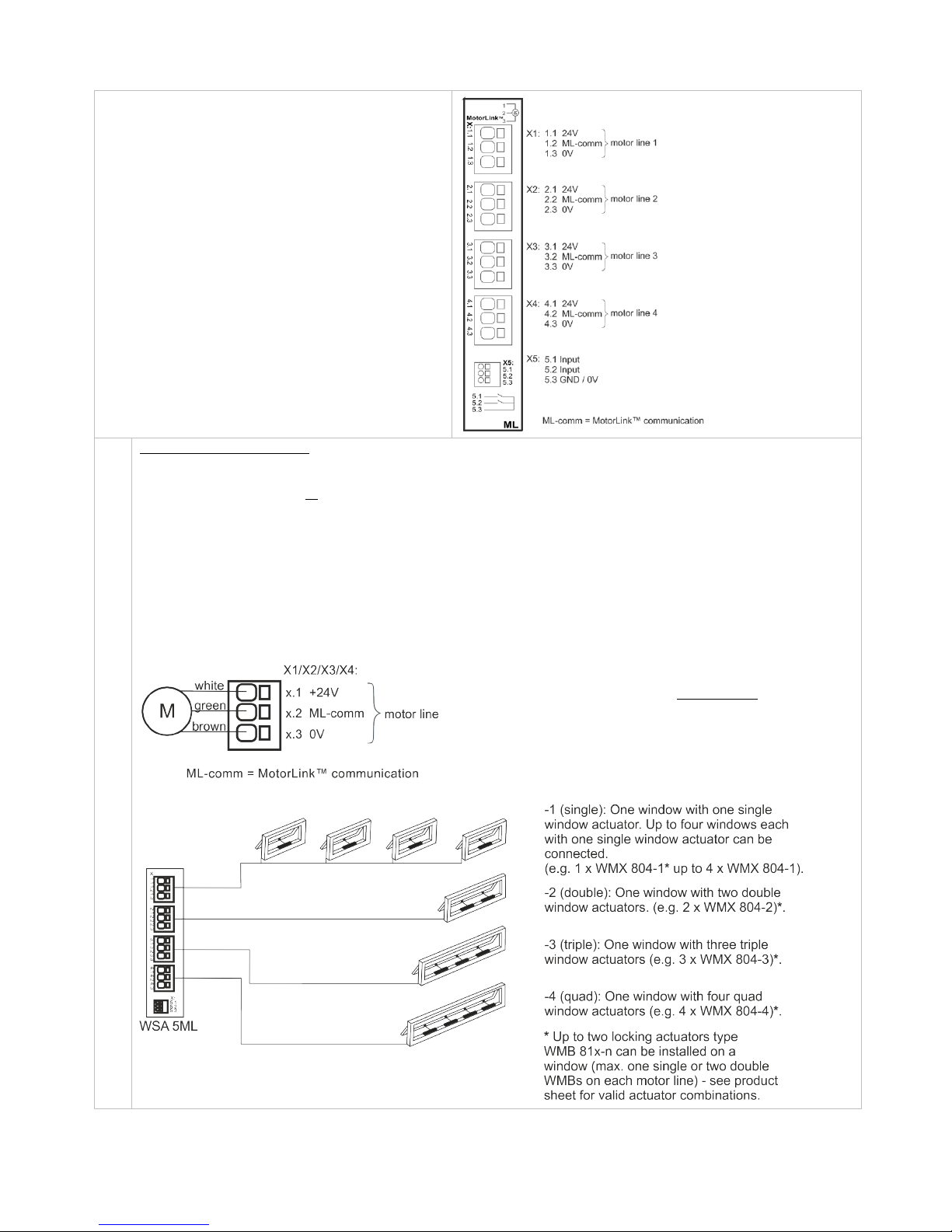
10.5 WSA 5ML MotorLink® motor module
WSA 5ML motor module provides:
- 4 motor lines for motors with MotorLink®
- 1 x 2 free configurable inputs for connection of e.g.
keypad or wind/rain sensor.
ML-comm = MotorLink® communication.
X1
X2
X3
X4
Motor line X1, X2, X3 and X4
The WSA 5ML module has four motor lines (X1, X2, X3 and X4) for connection of motors with MotorLink®
On each motor line up to four motors with a total power consumption of max. 10A can be connected; however the total
max power consumption for all four motor lines must not exceed 20A.
Besides motors also locking motors (espagnolette motors) type WMB 811/812 or WMB 01M/02M.can be connected.
The power consumption of the locking motors are not to be included in the 20A as motors and locking motors do not
run at the same time.
All motors on the same motor line will drive/be operated simultaneously.
For cable length se chapter “Cable dimensioning”.
Cable diameter: flexible max 6mm², solid 10mm. Flexible stranded cores are only suitable with attached ferrules. Max 1
core / ferrule per terminal.
Connect the motors accordingly to the drawing below.
Allowed motor combinations on a motor line
Examples with motors per motor line:
Ex. 1: 4 pcs. WMX 826-1
Ex. 2: 2 pcs. WMX 826-2
Ex. 3 2 pcs. WMU 885-2
Page 30
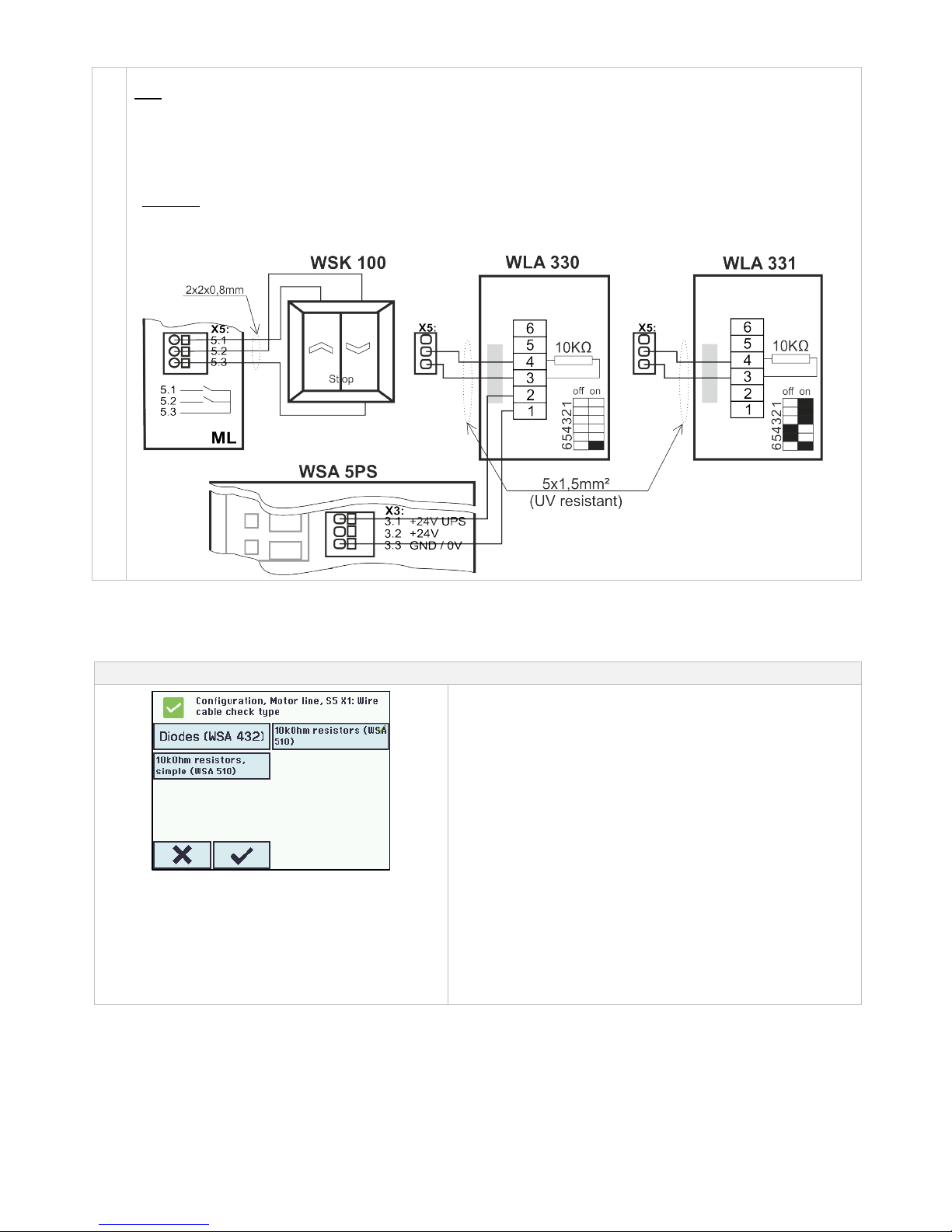
30
X5
Potential free connection for e.g. keypads, rain sensor or wind/rain sensor.
Data
Cable diameter: max 1.5 mm²
5.1 Input
5.2 Input
5.3 GND / 0V
See Chapter 10, Section 10.1, point X2 for detailed description about input options, cable monitoring etc.
Examples
- WSK 100 keypad for comfort ventilation
- WLA 330 wind/rain sensor
- WLA 331 rain sensor
11 Cable monitoring of motors
Motors with MotorLink® are monitored by data communication.
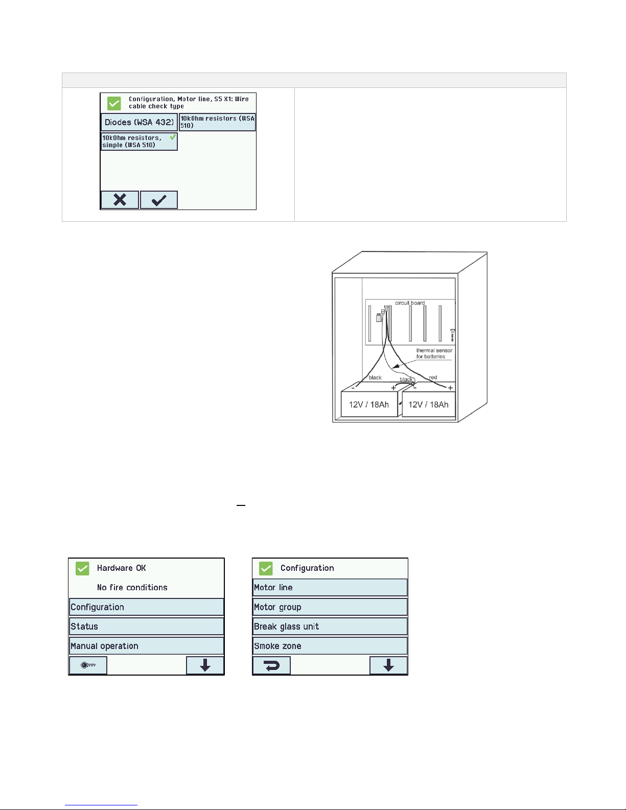
When using ±24V standard motors either diodes or 10kΩ resistors can be used for cable monitoring, see below.
Configuration of cable monitoring with ±24V motors
Configuration of cable monitoring
Diodes (WSA 432) – monitors ever single core for interruption.
Works with all WindowMaster motors. Meets the requirements of
prEN 12101-9.
WSA 5SM X1/X2/X3/X4
Note: short circuit between +24V (x.1) and monitoring wire (x.2 MLcomm) as well as breakage on +24V (x.1) can not be detected.
WSA 510 (WindowMaster standard) – monitors ever single core for
interruption. Works with all WindowMaster motors. Meets the
requirements of prEN 12101-9.
Simple WSA 510 – monitors for interruption on the entire cable.
Works with all WindowMaster motors and some non-WindowMaster
motors. Meets the requirements of
prEN 12101-9.
WSA 5SM X1/X2/X3/X4
Note: any short circuit or breakage on monitoring wire (x.2 MLcomm.) can not be detected.
Page 31
31
11.1 Usage of non-WindowMaster motors
When using non-WindowMaster motors the cable monitoring ist set to ”simple”’.
Configuration of cable monotoring with non-WindowMaster motors
Configuration of cable monitoring
If cable monitoring of non-WindowMaster® motors connected to the
FlexiSmoke™ is required the cable monitoring type is set to
”simple”.
Note: A few types of non-windowmaster motors can not run
together with FlexiSmoke™, due to the cable monitoring control
voltage. These motors can be brought to run, in some cases, if the
cable monitoring in the 4 motorlines of the module are switched off
and a 390Ohm / 5Watt resistor is mounted on each of the
motorlines in use.
12 Back-up batteries
Connect 2 pcs. back-up batteries type WSC 017 for
each 20A section.
See chapter 21 “Maintenance” for further information.
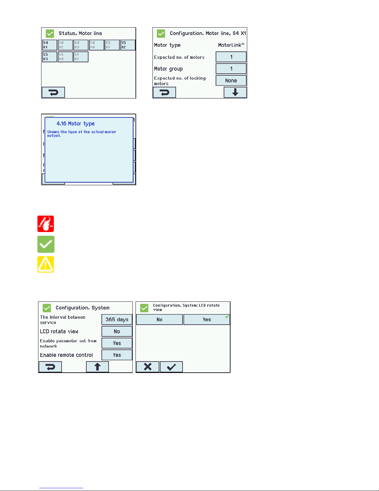
13 Touch screen
The smoke ventilation panel comes with one touch screen per 20A section i.e. that WSC 520 comes with one screen, WSC 540
with two screens and WSC 560 with three screens.
All connected components (motors, break glass units, keypads, weather station etc.) are to be configured on the touch screen. On
the WSC 540 (two touch screens) and the WSC 560 (three touch screens) the components can either be configured on the touch
screen in the section that they are connected or they can be configured on the other touch screen(s) in the smoke ventilation panel.
The menu of the touch screen is in steps:
Step 1: main menu
Step 2: sub menu
Step 3: configuration / showing / operation of the sub menu
Step 1: Main menu
Step 2: Sub menu
Page 32
32
Step 3: Overview of objects which are to
be configured
Step 4: Configuration of the sub menu
Help text
Help text
The touch screen has a help function with text explaining the menu item.
The help text occurs when the menu item is pressed (text on white
background).
For displaying the help text:
→ press the item e.g. “Motor type”
→ the help text appears
→ to turn off the help text press the screen.
13.1 Icons
The smoke ventilation panel has icons for quick viewing of: fire conditions, hardware OK and hardware error:
Fire conditions: smoke alarm has been triggered.
Hardware OK: motors and break glass units have been configured correctly.
Hardware error: hardware error or connected motors and break glass units has not been configured
correctly in motor lines, motor groups or smoke zones.
13.2 Rotation of the touch screen
The picture on the touch screen can be rotated 180°
14 Configuration – main menu
All connected components (motors, break glass units, keypads, weather station etc.) are to be configured.
As the panel has pre-settings for PIN code for access to level 3, the code is to be entered before it is possible to begin the
configuration (see chapter 14.16 “Log in”).
Before starting on the configuration it can be an advantage to change some of the pre-set settings. Ex. the language can be
changed from English to Danish or German (see section 13.15.1-1 “Language”) and the orientation of the text on the touch screen
can be rotated for a better viewing angle (see section 13.15.1-8 ”LCD rotate view”). It is also possible to change the log out time,
which is the time that the access to the access level is open/the touch screen in on (see section 13.12.1–3 – “Log out time”)
Page 33
33
To configure a sub menu:
→ press the light blue number field
→ enter value / the number of the motor line / change factory settings etc. The setting which can be entered depends of the
type of the sub menu.
→ accept on
A menu can consist of more screen plays. To get to the next screen: → press
14.1 Motor lines – motor groups – smoke zones
All the components are to be assigned to groups and zones:
- motor lines are to be assigned to motor groups
- motor groups can be assigned to smoke zones
- break glass units and smoke detectors are to be assigned to smoke zones
- keypads are to be assigned to one or more motor groups
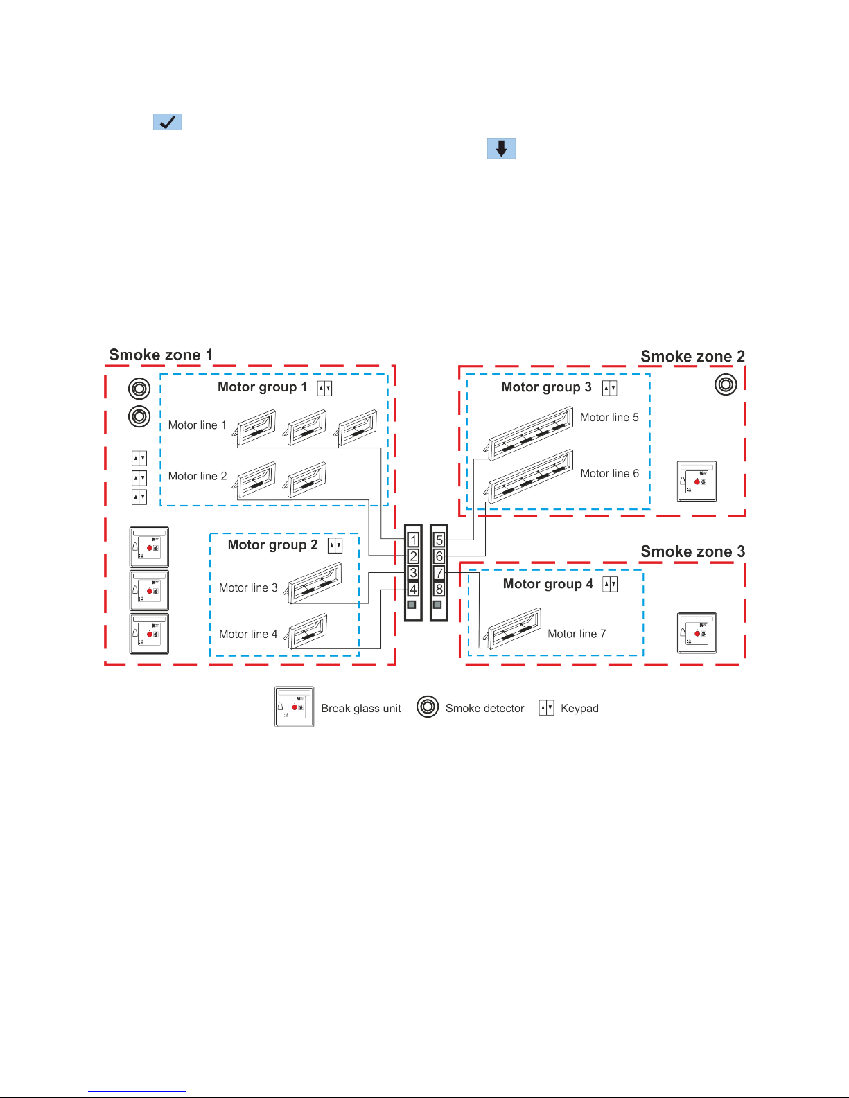
14.1.1 Examples with motor lines / motor groups / smoke zones
- 7 motor lines: one or more motors connected to the lines
- 4 motor groups: the motors in the motor group are operated simultaneously on the keypad
- 3 smoke zones: the motors in the smoke zone are operated simultaneously on the break glass unit
Page 34
34
14.2 Motor line
Motors are to be connected on the motor lines.
Depending the type of module either ±24V standard motors or motors with MotorLink® can be connected.
14.2.1 Motor line - numbering
All motor lines are numbered and they are all to be configured.
14.2.2 Motor line - configuration
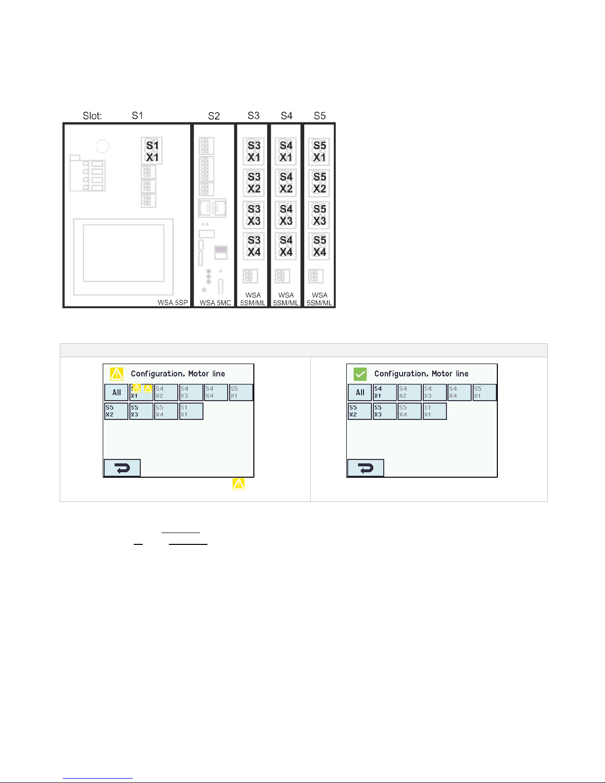
Press ”Motor line” and the overview of the motor lines in the smoke ventilation panel is shown.
Overview configuration motor lines
One motor line is marked with a
as the configuration is missing.
All motor lines are configured.
All motor outputs on the motor module as well as the single motor output S1.X1 on the WSA 5PS module are to be configured:
- Motor lines with motors connected are to be configured in “motor group
-
- Motor lines with no motor connected are set to “none“
Since ±24V motors and motors with MotorLink® are not to be configured exactly the same way, both type of motors are listed below
with the settings that are to be configured for each motor type.
Be aware that both types of motors can be connected to the smoke panel at the same time. ±24V motors can be connected in the
modules WSA 5PS and WSA 5SM and motors with MotorLink® can be connected on the module WSA 5ML.
Page 35
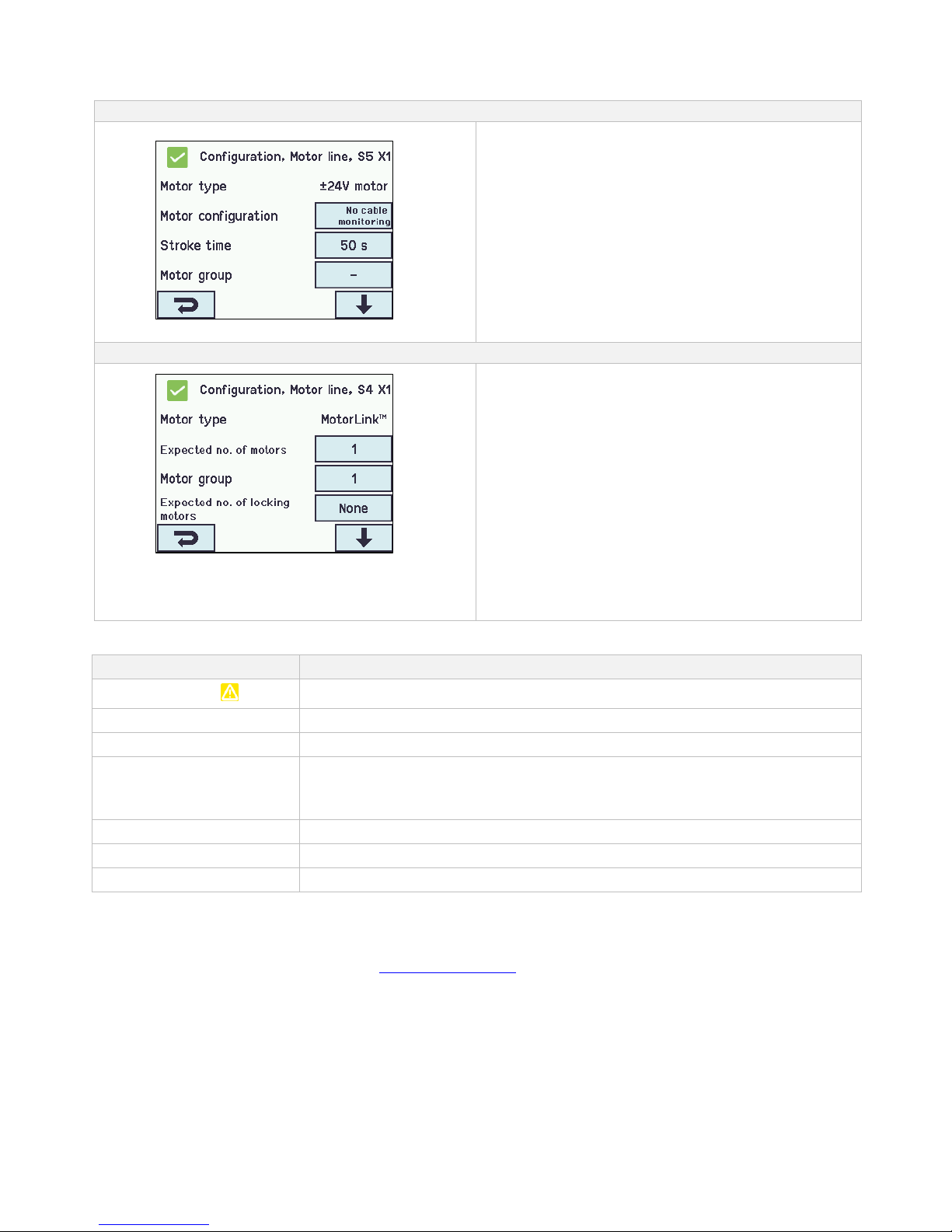
35
For ±24V motors the full chain length is defined as a runtime of 60 seconds. To ensure the windows are 100% open or closed, the
chain length is run twice (120sec). This can have an influence when configuring the a sequence control.
i
Motor lines configuration
±24V motor configuration
The ±24V motors are to be configured in:
1. Motor type: informs the type of the motor ±24V motor
(not to be configured)
2. Motor configuration
3. Stroke time
4. Motor group
5. Manual command - auto off-period
6. Retry during alarm
7. Sequential control type
The appendix contains all the menus that can be configured
- see appendix for detailed explanation.
The MotorLink® motors are to be configured in:
MotorLink® motor configuration
1. Motor type: informs the type of the motor MotorLink®
(not to be configured)
2. Expected no. of motors
3. Motor group
4. Expected no. of locking motors
4.1 No. of found locking motors (see appendix)
5. Manual speed
6. Auto. speed
7. Manual command – auto off period
8. Retry during alarm
9. Max unexpected overcurrent
10. Max unexpected overcurrent (motor)
11. Sequential type
The appendix contains all the menus that can be configured
- see appendix for detailed explanation.
14.2.3 Colour code - motor line
The overview fields on the touchscreen have color codes for the motor lines:
Colour
Meaning
Yellow triangle icon
The motor line are to be configured or there is a fault in the motor
Strikethrough grey
No configuration of the motor line / the motor line doesn’t exists
Black text
The motor line are configured, the motor has not been closed 100%
Green
The motor line has been configured; the motor has been closed 100%.
Motor lines on the MotorLink® module will be marked in green, if the motor/motors on the
motor line has been closed 100% and the point zero of the motor has been determined.
Light grey number
The motor line are configured with ‘No motors are connected’
Blue ?
Configuration is missing or there is a mistake in the configuration
Red
The motor line has been given alarm signal
14.3 Motor group
All motor groups can be assigned to a smoke zone and multiple motor groups can be assigned to the same smoke zone.
See the example "Example of motor lines / motor groups / smoke zones" in the beginning of this chapter for further details or the utilization
examples, which can be found on the home pages (www.windowmaster.com).
When configuration specify the number of the smoke zone that are to control the motor group.
Page 36
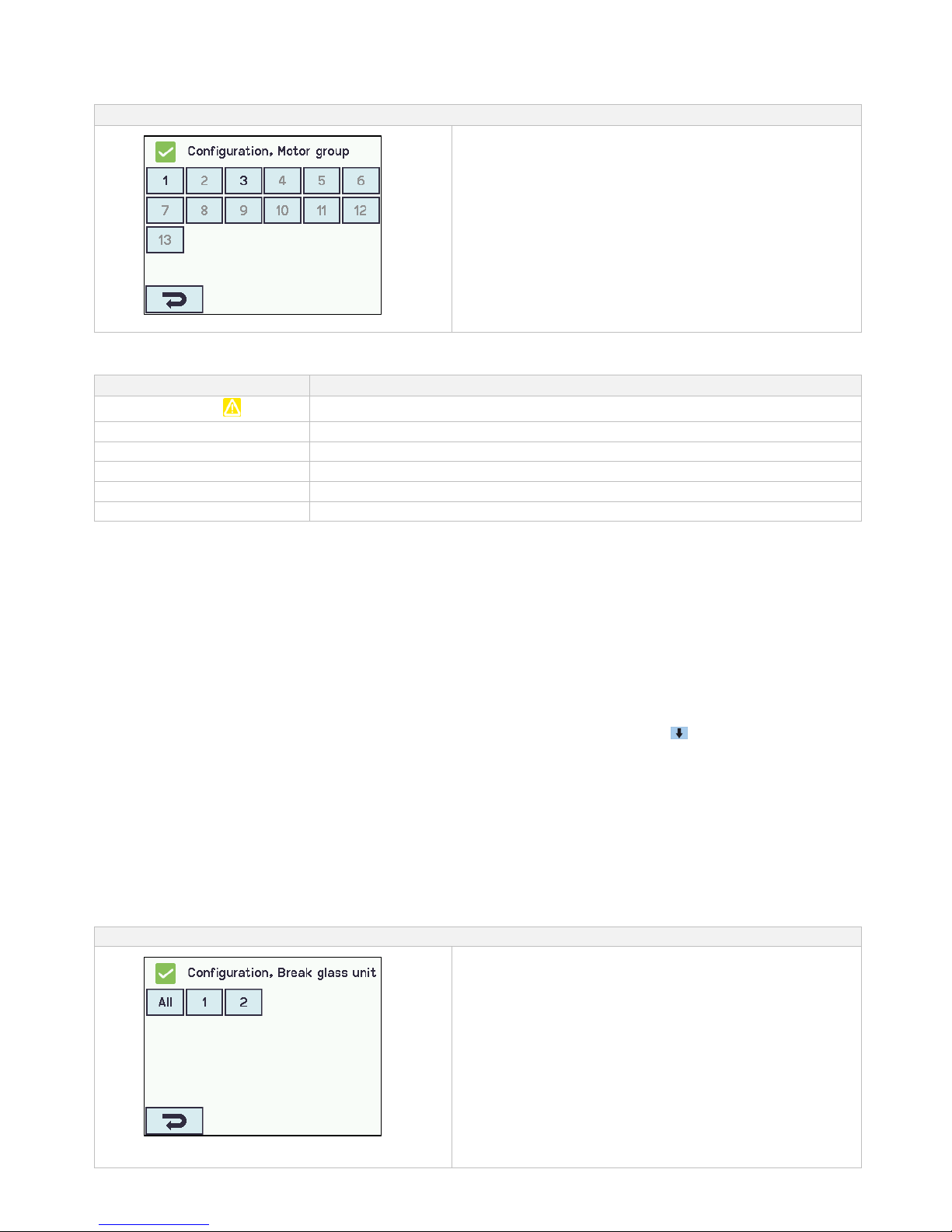
36
14.3.1 Motor group - configuration
Press ”Motor group” and the overview of the motor groups in the smoke ventilation panel is shown.
Motor group configuration
Motor group overview
Motor groups are to be configured in:
1. Controlling smoke zones
2. Comfort open position
3. Comfort open close time
4. Use ‘safety‘ from smoke zone
5. Wind directions where to close during alarm
The appendix contains all the items that can be configured
- see appendix for detailed explanation.
14.3.2 Colour code – motor group
The overview fields on the touch screen have colour codes for the motor groups:
Colour
Meaning
Yellow triangle icon
One or more of the assigned motor lines has a failure
Black text
The motor group is configured
Green field
All the assigned motor lines are closed
Light grey number
The motor group is configured but no motor lines are assigned
Blue ?
Configuration is missing or there is a mistake in the configuration
Red
The motor group has been given alarm signal
14.4 Break glass unit
A break glass unit shall be assigned to a smoke zone and multiple break glass units can be assigned to the same smoke zone.
See the example "Example of motor lines / motor groups / smoke zones" in the beginning of this chapter for further details.
14.4.1 Break glass unit – configuration
First the break glass units must be configured according to the topology (if they are connected one by one or in a ring) and then
follow the individual configuration of the break glass units according to smoke zones, comfort motor groups etc.
To be sure it is the right glass break unit that is configured; it is possible to locate the break glass unit in one of two ways:
1. Press the reset button and a blue speech bubble will appear in the selected break glass unit in the overview of the break
glass units.
2. Press the number of the selected break glass unit on the overview on the touch screen → press until the menu point
appears – “bip 1min for locating” is shown → press ”No” → select ”Yes”. The selected break glass unit will now beep if the door
on the break glass unit is closed.
Topology
The break glass units are monitored and the connection of the break glass units to the smoke ventilation panel depends of the
number of smoke zones:
1. when 1 smoke zone the break glass units are connected in series and connected directly to the WSA 5MC module
2. when 2 smoke zones the break glass units are connected in each their series and connected directly to the WSA 5MC module
3. when 3 or more smoke zones the break glass units are coupled in a ring
See section ”10.2 WSA 5MC overall control module” item ”X1” for further information on connection of break glass units.
Note: The break glass unit must be set in ring and the setting to "Yes" to have the error indication on the ‘All’ (group field) on the
overview of the break glass units.
Break glass unit configuration
Overview ’Break glass units
Overview ’Break glass units
Page 37
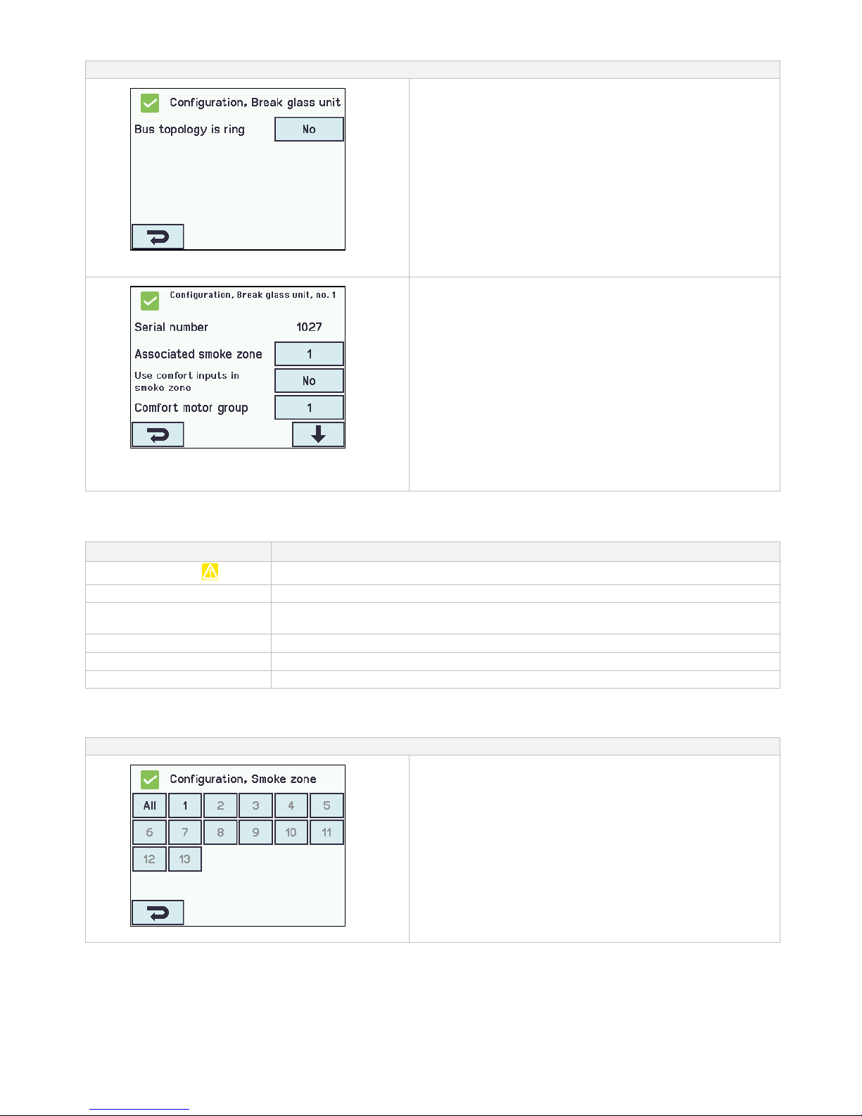
37
Break glass units are to be configured in:
Configuration of ‘Topology’
‘All’
1. Bus topology is ring - see text about “Topology” below
The appendix contains all the items that can be configured
- see appendix for detailed explanation.
Configuration of a selected ‘Break glass unit’
- shown for no.1
The numbered break glass units
1. Serial number: the break glass unit’s unique serial no. is
shown (cannot be configured)
2. Associated smoke zone
3. Use comfort inputs in smoke zone
4. Comfort motor group
5. Br.glass unit+sensor same smoke zone
6.1 Smoke sensor associated with smoke zone (displayed
only if ‘Other smoke zone‘ is selected)
6. Unit beep 1min for locating
7. Delete this unit
The appendix contains all the items that can be configured
- see appendix for detailed explanation.
14.4.2 Colour code – break glass unit
The overview fields on the touch screen have colour codes for the break glass units:
Colour
Meaning
Yellow triangle icon
Sensor error
Black text
The break glass unit are assigned to a smoke zone
Blue speech bubble
The reset-button in the break glass unit is pressed down (used when detecting break
glass unit)
Light grey number
The break glass unit is not assigned to a smoke zone
Blue ?
Configuration is missing or there is a mistake in the configuration
Red
The alarm button in the break glass unit is pressed down (alarm signal)
14.5 Smoke zone
Configuration of master/slave and control zones. Configuration of different opening limits of the windows when alarm is triggered.
Smoke zones configuration
Overview ’Smoke zones’
Overview ’Smoke zones
Page 38
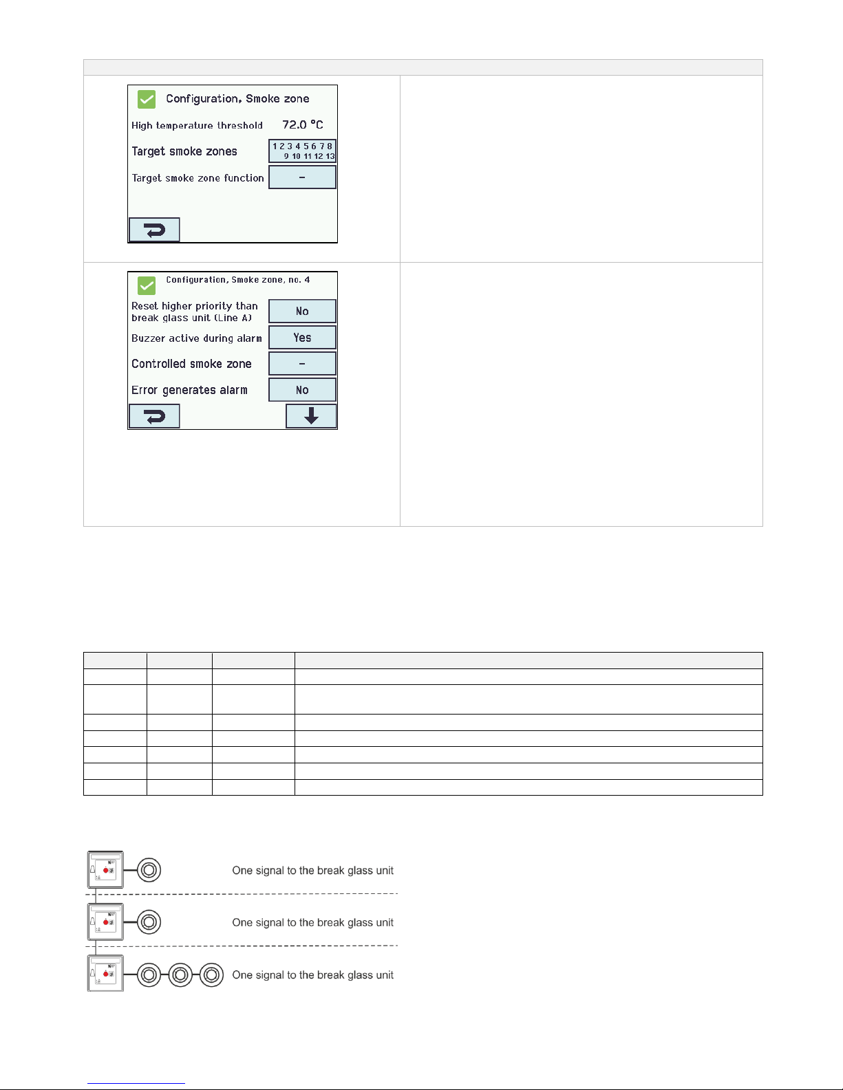
38
The smoke zone is to be configured in:
Configuration of ’All’
All
1. High temperature threshold
2. Target smoke zones
3. Target smoke zone function
The appendix contains all the items that can be configured
- see appendix for detailed explanation.
Configuration of a specific ’Smoke zone’
The numbered smoke zones
1. Reset higher priority than break glass unit (Line A) – see
explanation and table below
2. Buzzer active during alarm
3. Controlled smoke zone
6.1 Target smoke zone function (displayed only if one or
more smoke zones is/are selected)
4. Error generates alarm
5. Slave 1 of this smoke zone
6. Slave 2 of this smoke zone
7. Slave 3 of this smoke zone
8. Slave 4 of this smoke zone
9. Line B (smoke detector) smoke opening pos.
10. Use comfort commands
11. Use comfort commands from slaves
12. Wind direction speed threshold
The appendix contains all the items that can be configured
- see appendix for detailed explanation.
Wind direction dependent smoke ventilation
Note that when configuring a Master/Slave system, for Wind direction dependent smoke ventilation, the Master zone must reside in
the section which the Weather Station is physically connected to.
Line
Some of the functions referrers to ‘Line’.
Line A Alarm has the highest priority and Line F Alarm has the lowest priority.
The % value for the lines is configurable for each smoke zone. This is done in ‘View all details’. Furthermore, in “View all details”
Line E and Line F can be given the highest priority, this can be used for fireman’s override panels.
Line
%
Function
Used for
A
100%
open
break glass unit
B
100%
open
smoke detector (Switzerland: the value is often set to 0%, thus the windows will
close when smoke)
C
100%
open
D
0%
close
E
100%
open
F
0%
close
Reset
if this is selected the chosen function(s) will be reset
Number of smoke detectors to give an alarm:
If it is selected, that the alarm is only triggered when more smoke detectors give alarm, the smoke detectors are to be connected to
separate smoke detector – see drawing:
Page 39
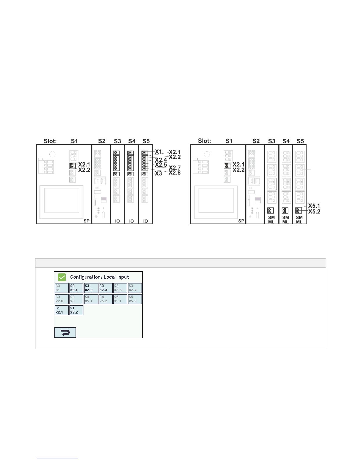
39
14.6 Local input
The smoke control unit has always two inputs on the WSA 5PS module (input number S1 X2.1 and S1 X2.2).
If further inputs are needed, insert the input/output module WSA 5IO.
This module has eight local inputs.
There can maximum be 26 inputs in a 20A section: 3 input/output modules each with eight inputs as well as the two inputs on the
power supply module WSA 5PS.
The touch screen has an overview of the local inputs. Please note that the overview consists of two pages if there are inserted 3
input/output modules.
14.6.1 Numbering of local inputs
All local inputs are numbered.
The number of the input depends on the location of the module - see example below.
Order of modules
The input/output module is as standard inserted in slot 3.
If further modules (input/output and/or motor modules) are added, the input/output modules are inserted before the motor modules
and MotorLink® motor modules before standard ±24V motor modules.
Examples with local inputs
a) Smoke ventilation panel with three Input-/output modules b) Smoke ventilation panel with three motor modules
14.6.2 Local input - configuration
If component are installed in one or more inputs, these inputs are to be configured.
Which item to be configured depends on the type of input – see description below.
Local input - configuration
Overview ’Local input’
Example of overview ’Local input’
Page 40
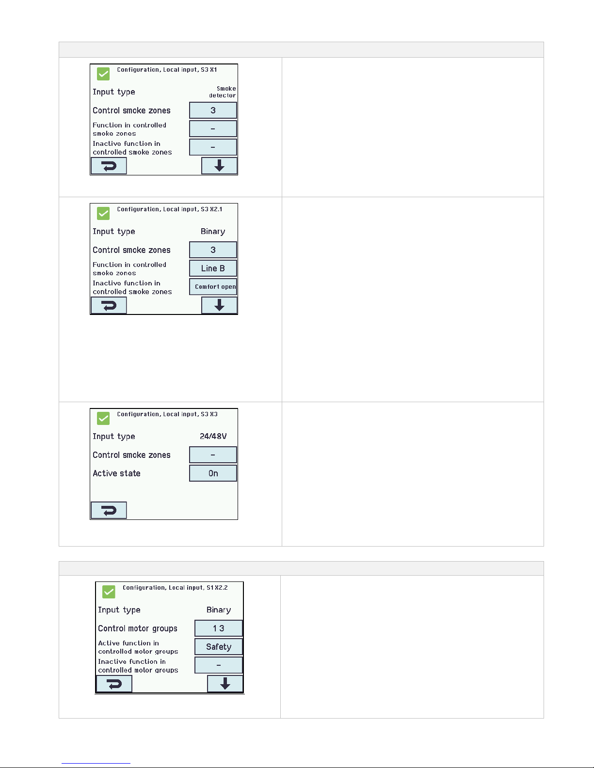
40
Local inputs are to be configured in:
Configuration of local input S3 on X1
Input X1 on WSA 5IO (smoke detector)
If a smoke detector is connected in the local input X1 on the WSA
5IO module, it shall be configured in:
1. Input type: informs the type “smoke detector” (not to be
configured)
2. Control smoke zones
2.1 Function in controlled smoke zones (displayed only
if ‘Control smoke zones‘ is selected)
2.2 Inactive function in controlled smoke zones
The appendix contains all the items that can be configured - see
appendix for detailed explanation.
Configuration of local input X2 and X5
Input X2 on WSA 5IO and X5 on WSA 5SM and/or WSA
5ML (binary)
If there is connected in the local inputs on the module/modules
WSA 5IO-, WSA 5SM- and/or WSA 5ML, it/they shall be
configured in:
1. Input type: informs the type of the input “Binary) (is not to be
configured)
2. Control smoke zones*
2.1 Function in controlled smoke zones (displayed only
if ‘Control smoke zones‘ is selected)
2.2 Inactive function in controlled smoke zones
3. Control motor groups*
3.1 Function in controlled motor groups
3.2 Inactive function in controlled motor groups.
* The input can either control smoke zones or motor groups.
When one is selected the other option will disappear from the
touch screen.
The appendix contains all the items that can be configured - see
appendix for detailed explanation.
Configuration of local input X3
on the WSA 5IO module
Input X3 on WSA 5IO (24V/48V) (primary used in France)
If there is connection in X3 on the module WSA 5IO, it shall be
configured in:
1. Input type informs the type “24/48V” (not to be configured)
2. Control smoke zones
2.1 Function in controlled smoke zones (displayed only
if ‘Control smoke zones‘ is selected)
3. Active state
The appendix contains all the items that can be configured - see
appendix for detailed explanation.
14.6.3 Usage of wind/rain sensors - WLA 33x
Usage of wind/rain sensors WLA 33x with motor groups (MG):
The used input e.g. S1X2.2 is configured to “Control motor groups”,
the groups are chosen.
Then, in the menu “Active function in controlled motor groups” the
function “Safety” is selected.
Then, the “Inactive function” is selected, which is the function the
input applies to the associated motor groups when it becomes
inactive.
By each motor group it is possible to define the max opening for
“Safety”, meaning it is possible to allow windows and louvers inside
the building to open despite “Safety” (wind/rain).
Facade windows, which are allowed to open e.g. 10%, to open
despite it rains.
Page 41
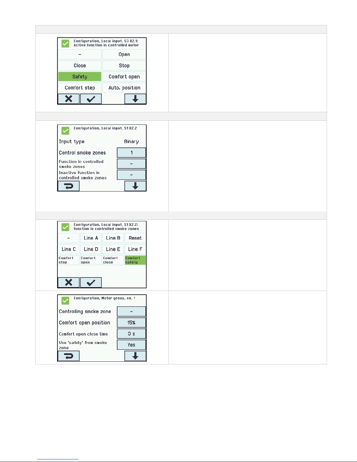
41
Input shall be configured in:
Configuration of local input
1. In the motor groups configure the input with the function “Safety“.
2. Configure the motor groups when anything else than close (0%) is
desired.
Usage of wind/rain sensors WLA 33x with smoke zones (SZ):
The used input e.g. S1X2.2 is configured as “Control smoke zones”
with the function “Comfort safety”
When an input is configured as “Smoke zones” and “Comfort safety”
has been selected, there must in the configuration of all the motor
groups be selected “Yes” to “Use ‘safety’ from smoke zone”.
Standard setting is “Yes”
If there in the configuration of the smoke zone has been chosen a
slave-smoke zone, safety information is automatically transmitted to
the slave smoke zone.
Input shall be configured in:
Configure the input with “Comfort safety” as “Function in controlled
smoke zones”.
1. Configure the motor groups to “Use ‘safety’ from smoke zone” =
Yes.
2. Configure if needed also the motor groups in the slave zones with
“Use ‘safety’ from smoke zone” = Yes.
14.7 Local output
On the WSA 5PS module the smoke ventilation panel has always one output for fault signal (not configurable output).
If further outputs are needed insert an input/output module type WSA 5IO which has four local outputs.
The max number of outputs in a 20A section is 13: 3 input/output modules each with four outputs and the output on the power
supply module WSA 5PS.
14.7.1 Numbering of local output
All local outputs on the input/output module are numbered.
The number of the output depends on the location of the module - see example below.
As the output (fault signal) on the WSA 5PS module cannot be configured it is not numbered.
Page 42
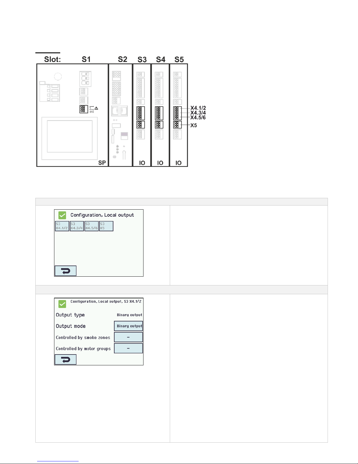
42
Order of modules
The input/output module is as standard inserted in slot 3 and if further modules (IO and/or motor modules) are added, the IO
module is inserted before the motor module.
Example
Example: Smoke ventilation panel with 3 x IO modules
14.7.2 Local output - configuration
If component are installed in one or more outputs, these outputs are to be configured.
Which item to be configured depends on the type of output – see description below.
Local output - overview
Overview ’Local output’
Overview ’Local output’
Local output shall be configured in:
Configuration of at local output
(shown for S3 X4.1/2)
1. Output type: informs the type ‘Binary output’ (is not to be
configured)
2. Output mode
2.1 Controlled by smoke zones (displayed only when ‘Siren‘ is
selected)
2.2 Time out
2.3 Smoke zones output functions
3. Controlled by smoke zones* (displayed only when ‘output
mode is selected to ‘Binary output‘)
3.1 Smoke zone output functions
3.2 Logic function
3.3 Status when active
3.4 Time out
4. Controlled by motor groups
a) Motor group output function
b) Logic function
c) Status when active
d) Time-out
* The output can either control smoke zones or motor groups.
When one is selected the other option will disappear from the
touch screen.
The appendix contains all the items that can be configured - see
appendix for detailed explanation.
Page 43
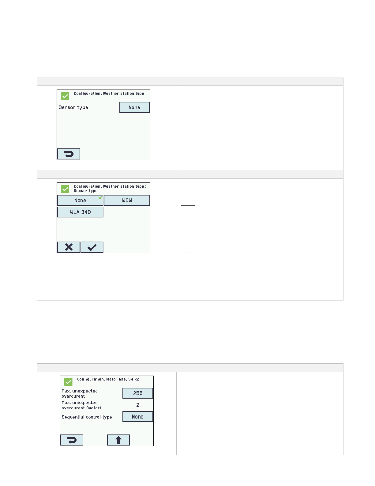
43
14.8 Weather station type
Here is to be selected which type of weather station – none, WOW or WLA – that is connected.
(The menu “Weather station” is only used for input from WSA 5MC input S2X3.2. If WLA 340 is selected a wind speed (pulse) signal is
received from the WLA 340. If WOW is selected a wind speed and wind direction (serial communication) signal is received from WOW
201/202. See section 10.2 in the installation instruction).
WLA 33x is not a weather station and is connected directly to an input, see section 14.6.3
Weather station - configuration
Overview ’Sensor type’
Overview ’Sensor type’ (selection of type of weather station)
Weather station shall be configured in:
Configuration of the sensor
None
(no configuration)
WOW
1. Filter constant
2. Slow filter constant
3. Use RMS in filter
4. Retransmit time
The appendix contains all the items that can be configured - see
appendix for detailed explanation.
WLA
1. Pulses/sec. per m/s
2. Filter constant
3. Slow filter constant
4. Use RMS in filter
5. Retransmit time
The appendix contains all the items that can be configured - see
appendix for detailed explanation.
14.9 Sequence control
The sequence control functionality is used where the movement of a motor line must depend on an external event or situation/stage.
To be used where window flabs are overlapping or where the windows cannot open (e.g. more than 15%) if the blinds are down a.s.o.
The sequence control can be controlled depending on;
- the position of a different motor line
- the state of a local input
- the state of a KNX object
- the state of a BACnet object
Sequence control configuration
Activation of sequence control
The activation of sequence control is to be done for each motor line.
Page 44
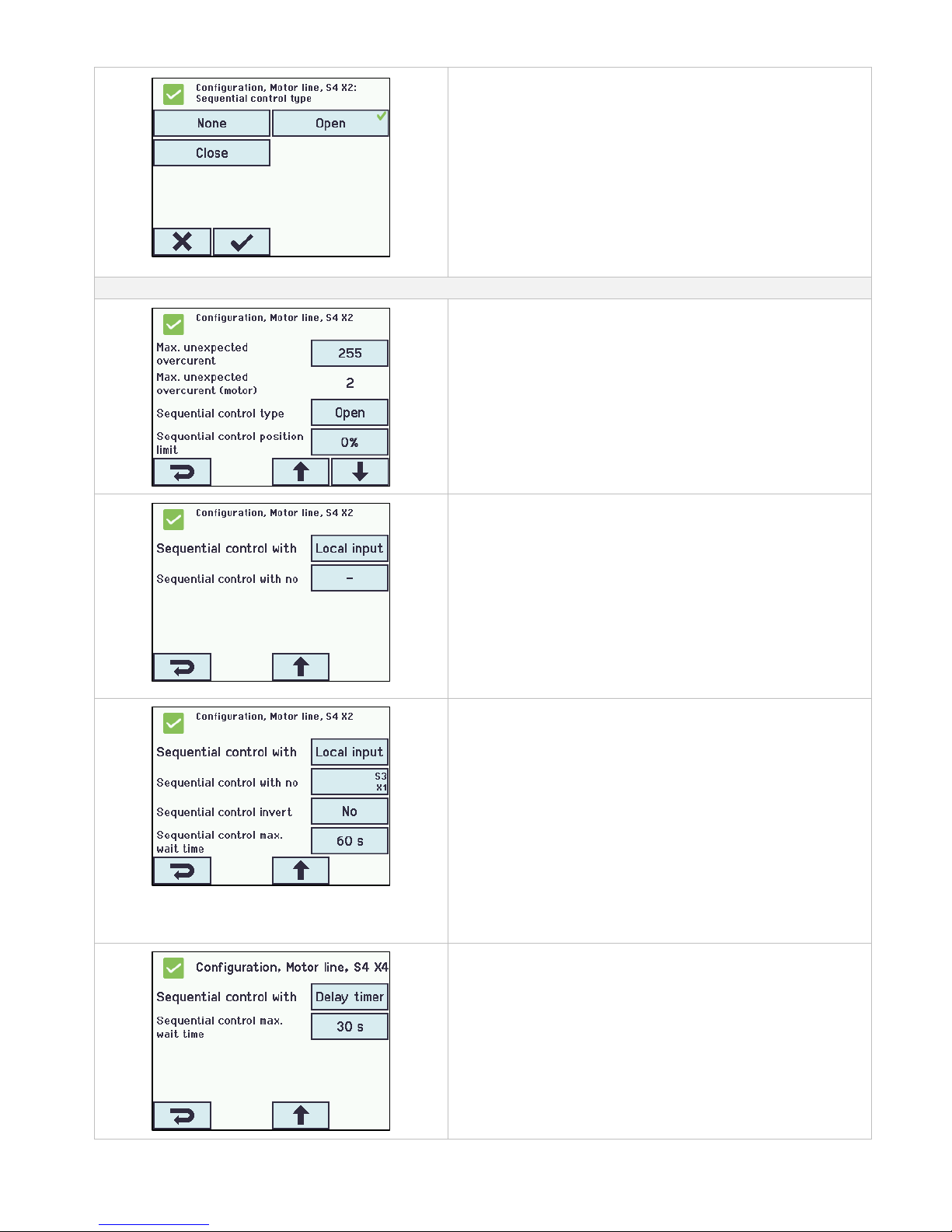
44
Sequence control configuration
The function for the sequence control is to be configured for each
motor line
1. None - This motor line does not use sequence control
2. Open - This motor line must wait for a “result” before opening
3. Close - This motor line must wait for a “result” before closing
Sequence control configuration – motor line
1. Max. unexpected overcuret
This is not a sequence control paramter
2. Max. unexpected overcurrent (motor)
This is not a sequence control paramter
3. Sequential control type
This motor line must wait for a „result“ before opening.
4. Sequential control position limit
the max position the motor line is allowed to have without the
„result“ is being fulfilled.
For MotorLink® motor lines stepless variable.
For ±24 Volt motor lines 0 or 100%
1. Sequential control with
Select the object the motor line is to wait upon.
Choose among another motor line, KNX-, BACnet-, local input or
delay timer.
1. Sequential control with
Upon which Motor line, KNX-, BACnet- or local input must the
motor line wait.
2. Sequential control with no.
Upon which Motor line, KNX-, BACnet- or local input must the
motor line wait.
3. Sequential control invert
No: waits for a close signal (active input )
Yes: waits for a open signal (inactive input)
4. Sequential control max. wait time
set the max wait time the motor line should wait, e.g. 60sec. the
motor line will then e.g. opens after 60 seconds even when the
input condition is not fulfilled. Values between 0 and 64,000
seconds are valid, both for comfort and smoke ventilation. When
set to 0 the motor line waites for ever.
1. Sequential control with
Delay timer
The motor line is set to wait for a certain period of time ‘Sequential
control max. wait time’. When the wait time has elapsed the motor
line will then move.
Page 45
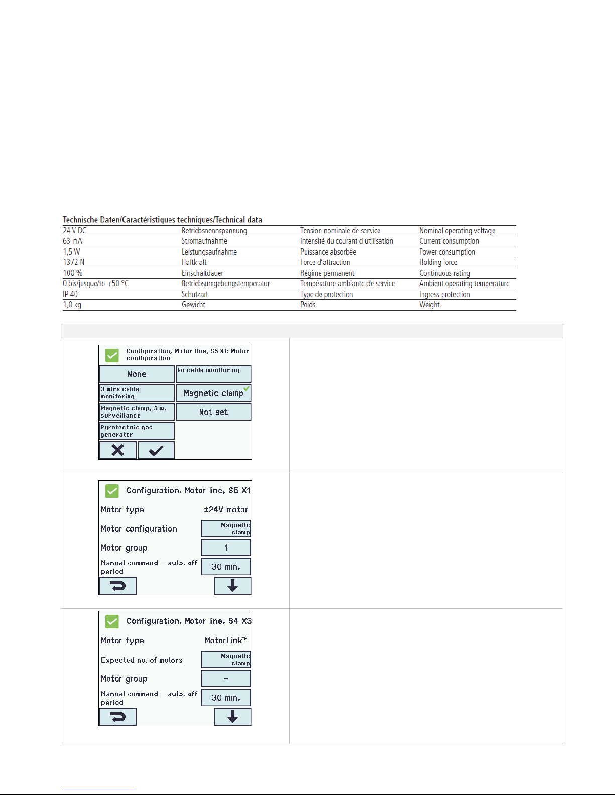
45
14.10 Magnetic clamp (magnetic door retainer)
Motor lines can be defined as magnetic clamps.
Per section up to max. 6A can be used for magnetic clamps, the remaining 14A are reserved for motors.
If a motor line is defined as magnetic clamp there will be power on the output as long as the panel is not
triggered in fire condition.
Note, in case of mains power failure, the motorline will also lose its power and the magnetic clamp will release the door.
If a motor line is defined as a magnetic clamp there will be no need of cable monitoring, as a cable
error will have the same function as fire condition. The cable monitoring can be selected if an error on
the cables is to be shown.
Technical data:
- Power consumption per magnetic clamp: minimum 5mA
- Current per section for magnetic clamp: maximum 6A
FlexiSmoke™ is tested with Hekatron THM 425-1.
Technical data (of Hekatron):
Configuration of magnetic clamp
Configuration of magnetic clamp
The configuration of magnetic clamp must be done for each motor
line.
Under the configuration of Motors line Magnetic clamp.
Konfigurering af Holdemagnet - ±24V motor
Each motorline (±24V motor) which is configured as a magnetic
clamp must be associated with a motor group.
Konfigurering af Holdemagnet - MotorLink® motor
Each motorline (MotorLink®) which is configured as a magnetic clamp
must be associated with a motor group.
Page 46
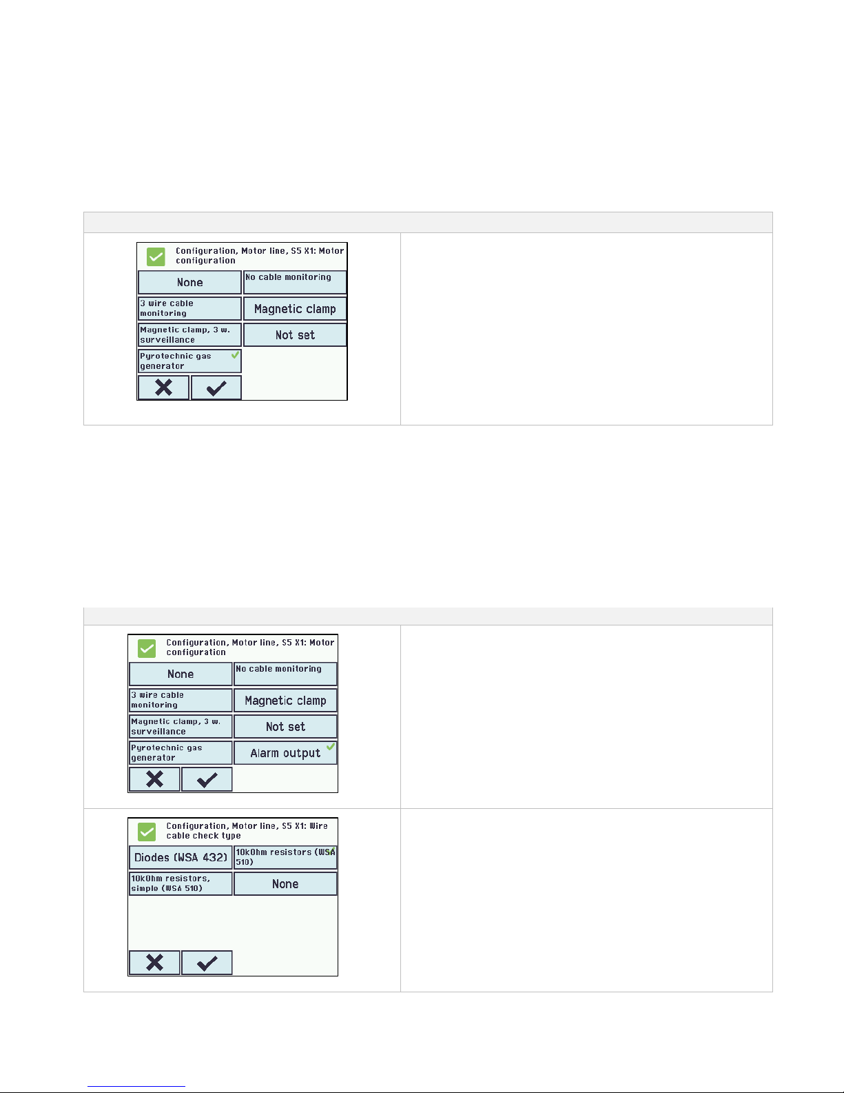
46
14.11 Pyrotechnic gas generator
A pyrotechnic gas generator is a pyrotechnic detonator, which is now supported on the ±24 Volt motor line outputs on the WSA 5PS
and WSA 5MS modules.
Typical data:
- Resistor: 1.4 to 1.6 Ohm
- 100% no ignition: 180 mA / 5 min. DC
- 100% ignition: 600 mA / 10 ms (DC)
- Test current: max: 10 mA
FlexiSmoke™ is tested with Chemring Typ 1.3.
Configuration of pyrotechnic gas generator
Configuration of pyrotechnic gas generator
The configuration of pyrotechnic gas generators must be done for
each motor line.
When a motor line is configured as pyrotechnic gas generator:
- it will not react on comfort commands
- the cable monitorin will detect cable interruption
- NO end of line motor modules (WSA 432 / 510) is to be
inserted
- motor line must be configured as pyrotechnic gas generator
BEFORE the generator is connected!
When more pyrotechnic gas generators are to be connected on the
same motor line they (max. 5 pcs) are to be connected in series.
For dimensioning of cable see section 0
14.12 Alarm output
A motor output can be configured as “Alarm output” for operating an external DC relay. The output becomes active according to the
motor group configuration.
Recommended relay:
Finder type 44629 028 000 (28V, not sensitive), coil impedance 1.2kΩ or similar.
The relay is connected to output S1, X1/X2/X3/X4 on the standard motor card.
Cable monitoring is possible. For full monitoring of all cables, the end of line motor module (WSA 510) is recommended.
Alarm output shall be configured in:
Configuration of alarm output
The configuration of alarm output must be done for each motor line.
Configuration of cable monitoring
The configuration of cable monitoring must be done for each motor
line.
Page 47
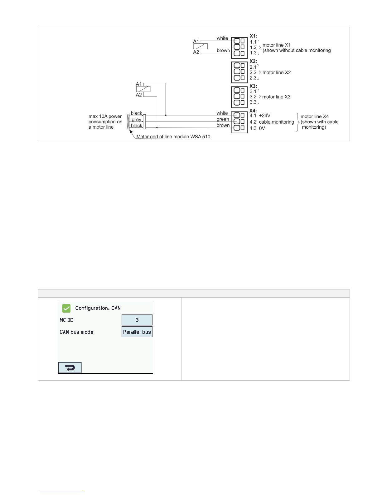
47
Connection of relay
14.13 CAN bus
More FlexiSmoke™ smoke ventilation panels can be connected via CAN bus.
FlexiSmoke™ uses a special communication format, so the CAN bus from a FlexiSmoke™ must not be connected to other
systems with CAN.
IMPORTANT
Each section that is connected with CAN shall for correct function be assigned with a unique 5MC ID.
When connecting more FlexiSmoke™ smoke ventilation panels, this configuration shall be done during commissioning or when
replacing a WSA 5MC module in one or more sections. This configuration is done under the menu item CAN.
The CAN bus is used for master/slave connection of smoke zones in multiple sections.
In applications where redundancy is required (to be sure an error in one smoke zone does not affect the function of another smoke
zone), both the CAN 1 and CAN 2 shall be connected between the smoke ventilation panels/sections. The sections in a
FlexiSmoke™ smoke ventilation panel are, when delivered from factory, connected with both CAN. If there is no need for
redundancy, the CAN bus mode can be set to "Independent buses".
Configuration is done in the sub menu: „Configuration → CAN → CAN-bus mode“.
It is not recommended to change the CAN-speed, which is factory set to 10 kbps.
Appendix contains all items that can be configured - see the appendix for detailed explanation.
The item "Operate other WSA 5MC module" in main menu on the touch screen allows to operate all sections that are connected via
the CAN bus (see chapter 18). Although there is a need to establish master/slave connection between several FlexiSmoke™
smoke ventilation panels, the option for remote control will often be of major benefit when commissioning and maintenance. If the
CAN is only used for commissioning and maintenance, there is only need for a single bus connection.
CAN bus shall be configured in:
Configuration of CAN
1. 5MC-ID
2. CAN bus mode
The appendix contains all the items that can be configured - see
appendix for detailed explanation.
Page 48
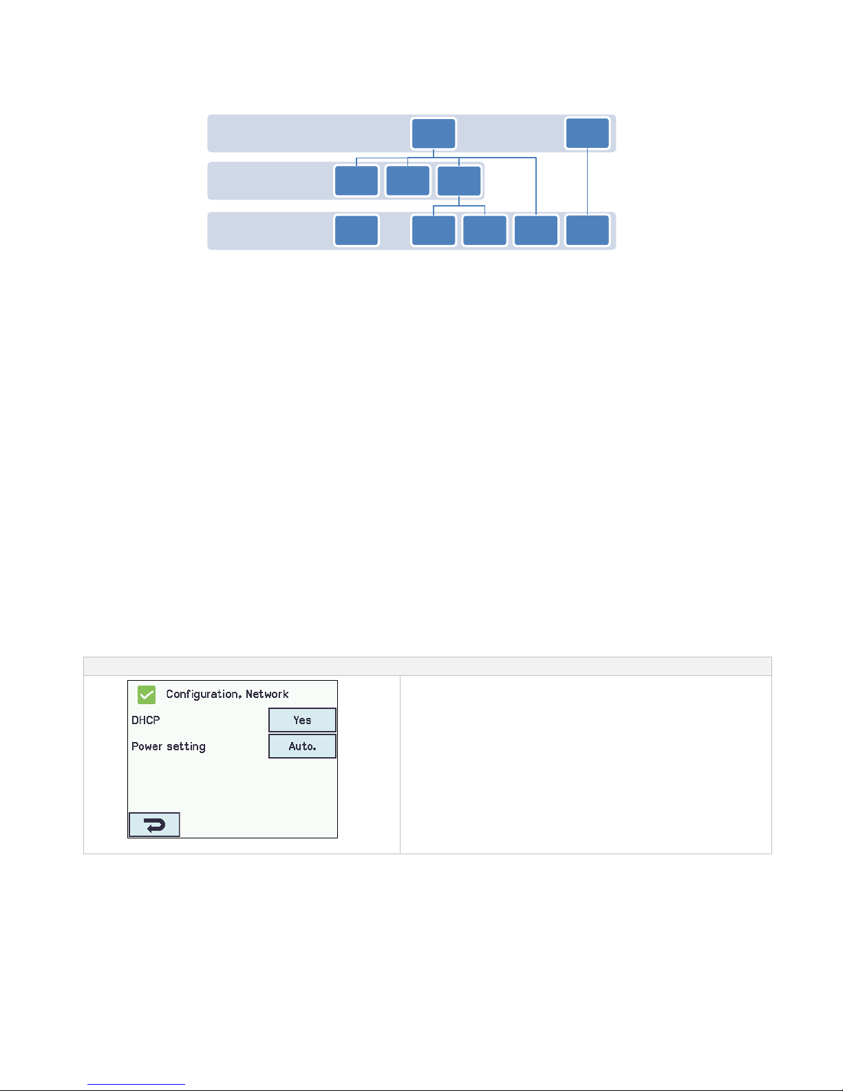
48
Master/slave connection of smoke zones
A smoke zone can be master for up to 4 other smoke zones. Master/slave connections can be established hierarchically. A slavesmoke zone can only be connected to one master.
MC-ID 1
Smoke
zone 1
MC-ID 2
Smoke
zone 3
MC-ID 3
Smoke
zone 2
Smoke
zone 2
Smoke
zone 3
Smoke
zone 4
Smoke
zone 5
Smoke
zone 2
Smoke
zone 1
Smoke
zone 1
Break glass units and input assigned to a slave-smoke zone are automatically sent to the master smoke zone. They are in the
evaluation of smoke on equal level as the local input on the master. The master sends the smoke commands to slaves, which only
receive input from the master. To get the fastest response, it is recommended that break glass units are assigned to the section in
which the master belongs.
When a smoke area (several smoke zones connected in a master-slave relation) consists of more sections and/or more master-slave
levels, it is necessary to press the the re-set button on the break glass unit for 5-10 sec to ensure that the close command reaches all
sections in the smoke zone.
A smoke zone (master or slave) can be configured to react / not react on associated keypads.
A smoke zone can be configured to react / ignore comfort commands from its slaves. If the smoke zone is configured to ignore
comfort commands from its slaves, these signals will not be send to the Master. This mechanism can be used to establish comfort
keypads which e.g. only operate a part of a larger smoke zone.
The configuration of a master/slave is done in the menu "Configuration smoke zone <n>" where each of the up to 4 slaves
connections can be selected from the connected and active sections.
14.14 Network
For configuring network addresses
The WSA 5MC module has a 10/100Mbit Ethernet connection. The connection support DHCP or fast IP address as well as
Gateway
It is possible to configure different power consumption profiles for the Ethernet connection. To burden the 72 hours back-up
batteries as little as possible, use the setting ‘Off’ or ‘Auto’ (factory setting).
The appendix contains all the items that can be configured - see appendix for detailed explanation.
Network is used in connection with BACnet IP interface – for further information see the “WSC 5xx Protocol Implementation
Conformance Statement (PICS)” on the home pages (www.windowmaster.com).
Network shall be configured in:
Configuration of ’Network’
1. DHCP
2. Power setting
The appendix contains all the items that can be configured - see
appendix for detailed explanation.
Page 49
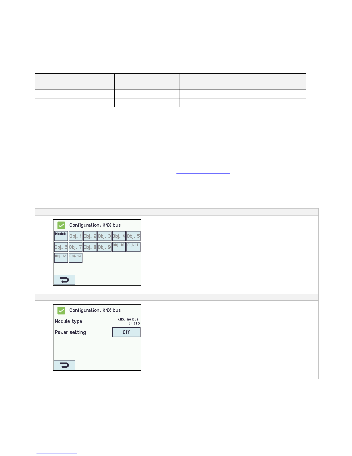
49
14.15 Fieldbus
”Module”
The WSA 5MC module is available in different versions with different possible connection of a fieldbus for status and comfort
operation.
Note: Smoke ventilation function has higher priority than comfort commands from the field bus and it is recommended only to use
field bus for comfort purposes.
Overview for WSA 5MC versions
Version
Type of letter in
the item number
BACnet IP
support
Field bus, Type,
Media
WSA 5MC NCO
0
No
None
WSA 5MC KNX
K
Yes
KNX TP1
14.15.1 KNX-bus
There is a set of KNX objects available for each motor line, motor group and smoke zone, which provides the options for status and
commands.
Status options
E.g. actual position, fault and operation status and the max opening angle (degrees).
Command options
E.g. target position commands with different priority and MotorLink® motor speed.
See "KNX Application Program Description " on the home pages (www.windowmaster.com) for further information on available
KNX communication objects.
Fieldbus link - "Conn. 1-13 "
The KNX has also 13 configurable binary communication objects.
These can either be used for sending comfort commands to one or more motor groups or to give selected status from smoke zones
or motor groups.
KNX bus configuration
KNX bus overview
Overview ’KNX bus’
KNX bus shall be configured in:
Configuration of ’KNX bus’
1. Module type
2. Power setting
The appendix contains all the items that can be configured -
see appendix for detailed explanation.
14.15.2 BACnet
There is a set of BACnet objects available for each motor line, motor group and smoke zone, which provides the options for status
and commands.
Status options
E.g. actual position, fault and operation status and the max opening angle (degrees).
Page 50
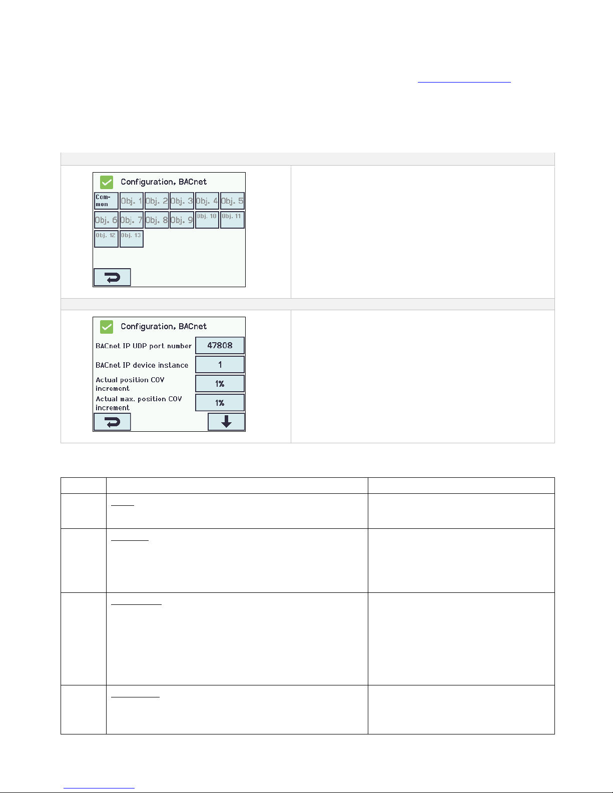
50
Command options
E.g. target position commands with different priority and MotorLink® motor speed.
See " WSC 5xx Protocol Implementation Conformance Statement (PICS)" on the home pages (www.windowmaster.com) for further
information on available BACnet communication objects.
Fieldbus link - "Conn. 1-13 "
The BACnet has also 13 configurable binary communication objects.
These can either be used for sending comfort commands to one or more motor groups or to give selected status from smoke zones
or motor groups.
BACnet configuration
BACnet overview
Overview over BACnet
BACnet shall be configured in:
Configuration of Module
1. BACnet IP UDP port number
2. BACnet IP device instance
3. Actual position COV – increment
4. Actual max. position COV- increment
The appendix contains all the items that can be configured -
see appendix for detailed explanation.
14.16 Log in
The access level to the smoke ventilation panel is set in four levels.
Level
Access to
Who has access
1
Public
You can see the smoke ventilation panel from the outside with
the door closed and locked
Everyone
2
Operation
You can open the panel house and operate the touch screen
for showing the status and manual operating of the windows.
All the menus on the touch screen can be viewed but no values
can be changed.
Chosen persons with a special key
3
Configuration
You can open the panel house and operate the touch screen
for showing status, manual operating of the windows as well as
configuration and changing the pre-set values.
All the menus and sub menus can be seen and the values can
be changed.
Access Level 3 can be locked with a PIN code, so there is only
access to the level when the PIN is entered
Chosen persons with a special key and
having the PIN code for access to level 3.
PIN code pre-set to 4321.
4
Maintenance
Administrative overall level: for operating as on access level 3
as well as updating with new software.
Access Level 4 is locked with a factory set PIN.
Only available for WindowMaster.
The function is locked with PIN code.
Page 51
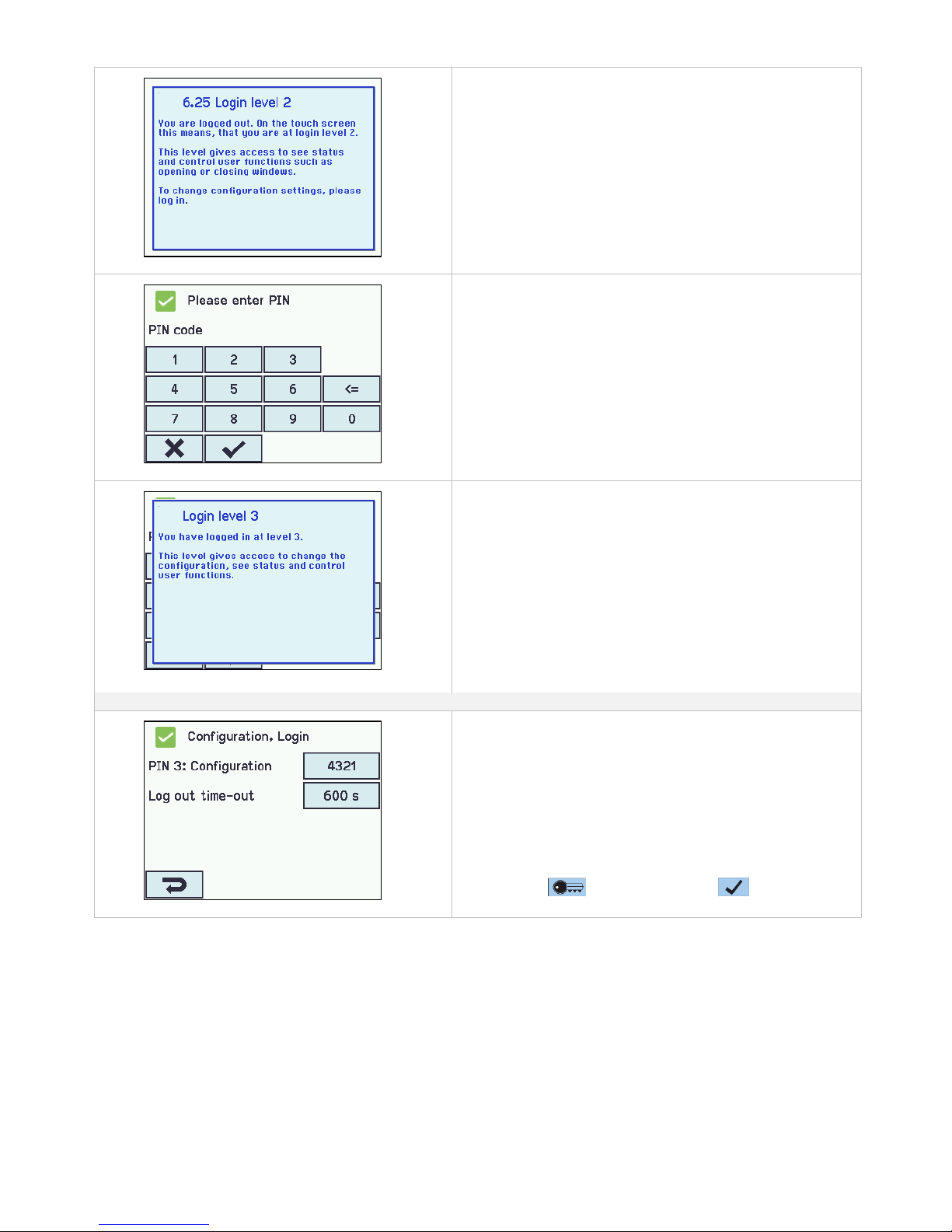
51
The user is on access level 2
The user is at access level 2.
To open for access level 3, enter the PIN for access level 3.
Enter PIN code
Enter PIN code.
Access approved to login level 3
The user is at access level 3.
Login shall be configured in:
Configuration of login
The access levels can be locked and access to the level is only
possible with a PIN code.
Each level has a unique PIN code.
1. PIN 3: Configuration
2. Log out time-out (the period of access to the level before the
system automatically lock the level)
The appendix contains all the items that can be configured -
see appendix for detailed explanation.
It is possible to lock the touch screen before the time has
expired: press followed by pressing
14.17 Configuration files on SD
The panel has a plug in for micro SD card.
The card is used for log file and back up of the configuration of the panel. The card should NOT be removed.
It is possible to save all the configurations of the panel and this way save the card as documentation.
It is also possible to reinstall from the SD card or to copy to an USB stick.
Copying to/from the SD card is to be done section by section – meaning that there are to be made 3 savings for a WSC 560.
The SD card’s file names are numbered from 1 to 24.
Files on the card can be transferred to a spread sheet (Excel).
Page 52
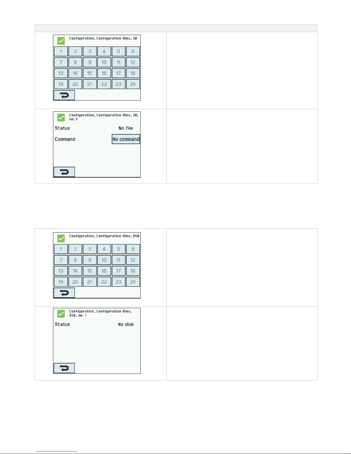
52
Configuration files on SD
Configuration files on SD overview.
Configuration files on SD overview.
Configuration of configurations file on SD – no.1
Configuration of configurations file on SD – shown for no.1
14.18 Configuration files on USB
The panel has a plug in for an USB stick. It is possible to save all the configurations of the panel and this way save the stick as
documentation. It is also possible to reinstall from the USB stick.
Copying to/from the USB stick is to be done section by section – meaning that there are to be made 3 savings for a WSC 560.
The USB stick’s file names are numbered from 1 to 24.
Files on the USB stick can be printed from a computer.
Configuration ‘Configuration, files on USB’ – overview
Configuration files on USB – overview.
Configuration of ‘Configuration files on USB – no. 1’.
Configuration of configuration files on USB – shown for no. 1.
Page 53
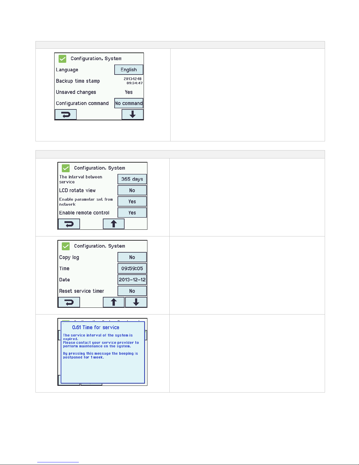
53
14.19 System
It is possible to change settings on the touch screen e.g. language, clock setting, date display, service timer etc.
System can be configured in:
Configuration of ’System’
1. Language
2. Backup time stamp (not to be configured)
3. Unsaved changes… (not to be configured)
4. Configuration command
5. Copy log
6. Time
7. Date
8. Reset service timer
9. The interval between service
10. LCD rotate view
11. Enable parameter set from network
12. Enable remote control
The appendix contains all the items that can be configured -
see appendix for detailed explanation.
14.19.1 Service timer
Configuation of interval between maintenance:
Configuration of interval between service
The timer is set in “days until the next maintenance”. Typically, on
most markets, this will be 365 days.
If the interval between maintenances is set to 0, the timer is
disabled.
The acoustic notification can be activated or deactivated under
“View all details”
Reset off service timer
”Reset service timer” set the last maintenance date as today.
Message when the service timer expires
When the service timer expires the touch screen will show a
maintenance text and a clear beeping will sound from the panel.
Page 54
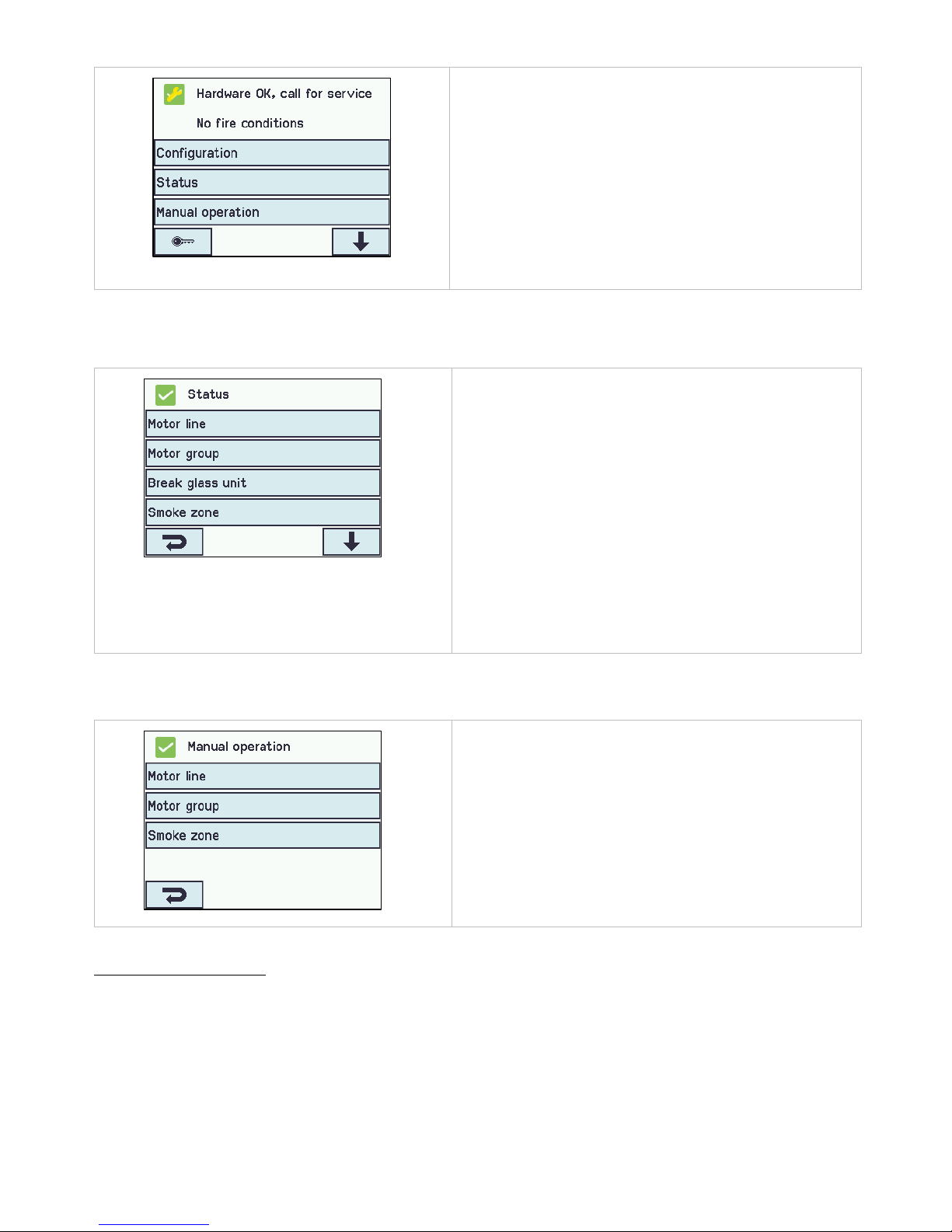
54
Main overview when the service timer
has been postponed
If you confirm the service timer by touching the touch screen, it will
be mute for a week, before the beeping sound starts again.
A maintenance icon will appear on the touch screen.
15 Status – main menu
In 'Status' you can see the status of all the menu items that can be configured under 'Configuration' as well as the status of the
power supply (including mains and battery status) and slots (inform the type of module in the slot).
Main overview: status of the system
Under ‘Status’ is possible to view the status for:
1. Motor line
2. Motor group
3. Break glass unit
4. Smoke zone
5. Local input
6. Local output
7. Weather station type
8. Power supply
9. CAN (local)
10. Ethernet
11. Slots
12. KNX Bus
13. System
It is not possible to configure the items in ’Status’ mode.
The appendix contains all the items shown in ‘Status’ - see
appendix for detailed explanation.
16 Manual operation – main menu
It is possible to operate the motor lines, the motor groups and the smoke zones direct on the touch screen.
Main overview: manual operation
What to be manually operated:
1. Motor line – see text below
2. Motor group
3. Smoke zone
Operation types
Motor lines and motor groups
They can be operated absolutely (percentage of full open) or relatively on the keypad ‘open/stop/close’ showed on the touch
screen.
Page 55
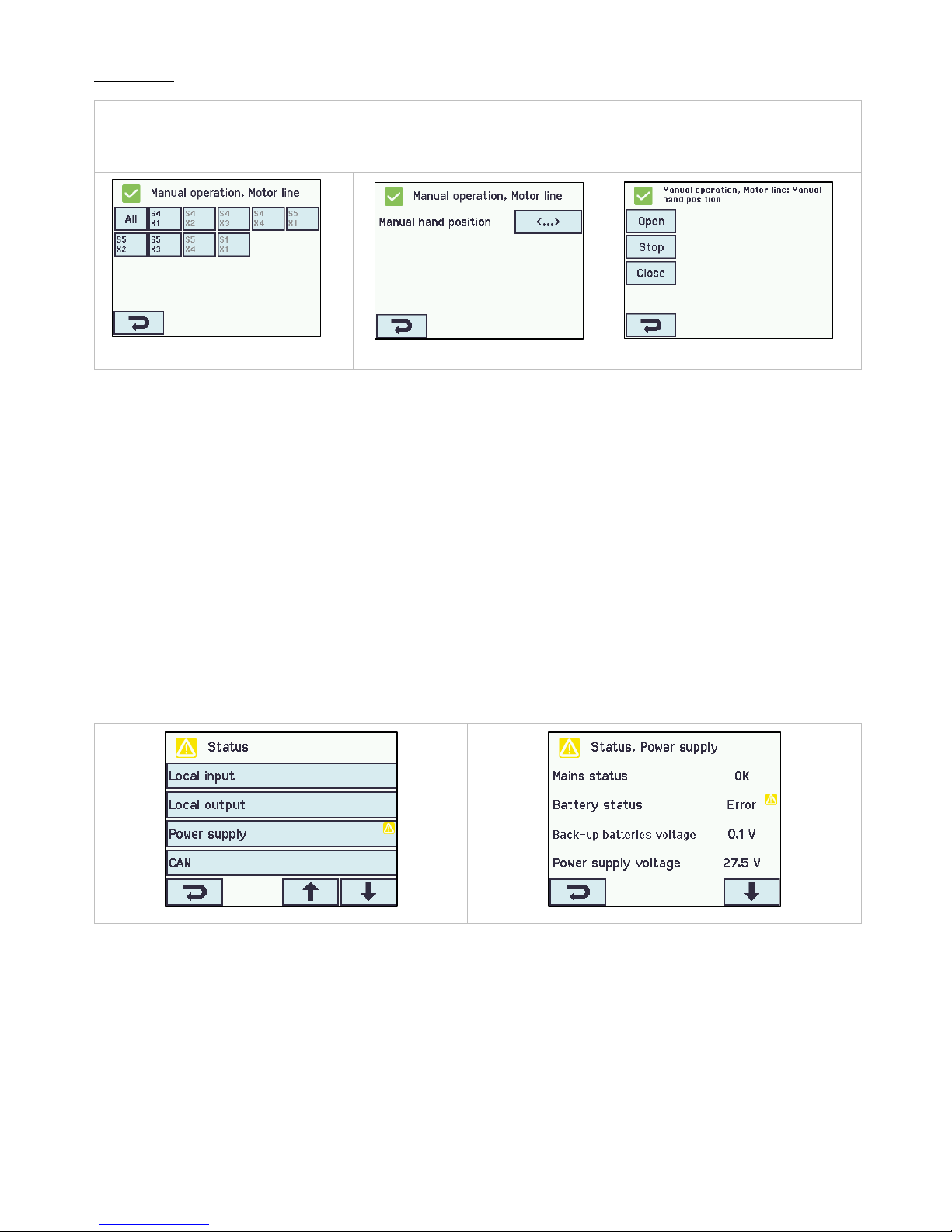
55
Smoke zones
They can be operated in ‘Alarm’ or ‘Reset’
Example
Manual operation of a motor line
- If ’All’ is selected all the motors are operated simultaneously.
- If a motor line number is selected only the selected motor line is operated.
Motor line - overview
One motor line is selected
Manual operation on the
touch screen
17 Configuration missing – main menu
If any components, motor lines, motor groups or smoke zones are not configured they are listed here.
If you are logged into access level 3 it is also possible to configure from this menu.
18 Hardware error – main menu
If there are any hardware error in a section, they will be displayed here.
E.g. if the motor lines are not configured, the main supply is cut of, the back-up batteries are not connected, the type of weather
station is not selected etc.
If you are logged into access level 3 it is also possible to configure from this menu.
18.1 Error on the Power supply
Mains power failure will trigger an error on the “Power supply”. The first 10 minutes (parameter setting) after the failure has been
detected, no error is indicated neither on the panel, the display nor in the break glass units.
The following 20 minutes the error will be indicated as a warning meaning the green LED on the break glass units will flash, on the
WSA-5MC module the green LED is still on and the yellow LED is turned off. 30 minutes after the mains power failure has been
detected all the green LED will turn off and the all the yellow LEDs in the smoke ventilation panel and the break glass units will lit
continuously.
Furthermore, non connected, wrong connected or ”dead” batteries can trigger an error on the ”Power supply”.
Error on the power supply
Error on the Battery status
Page 56
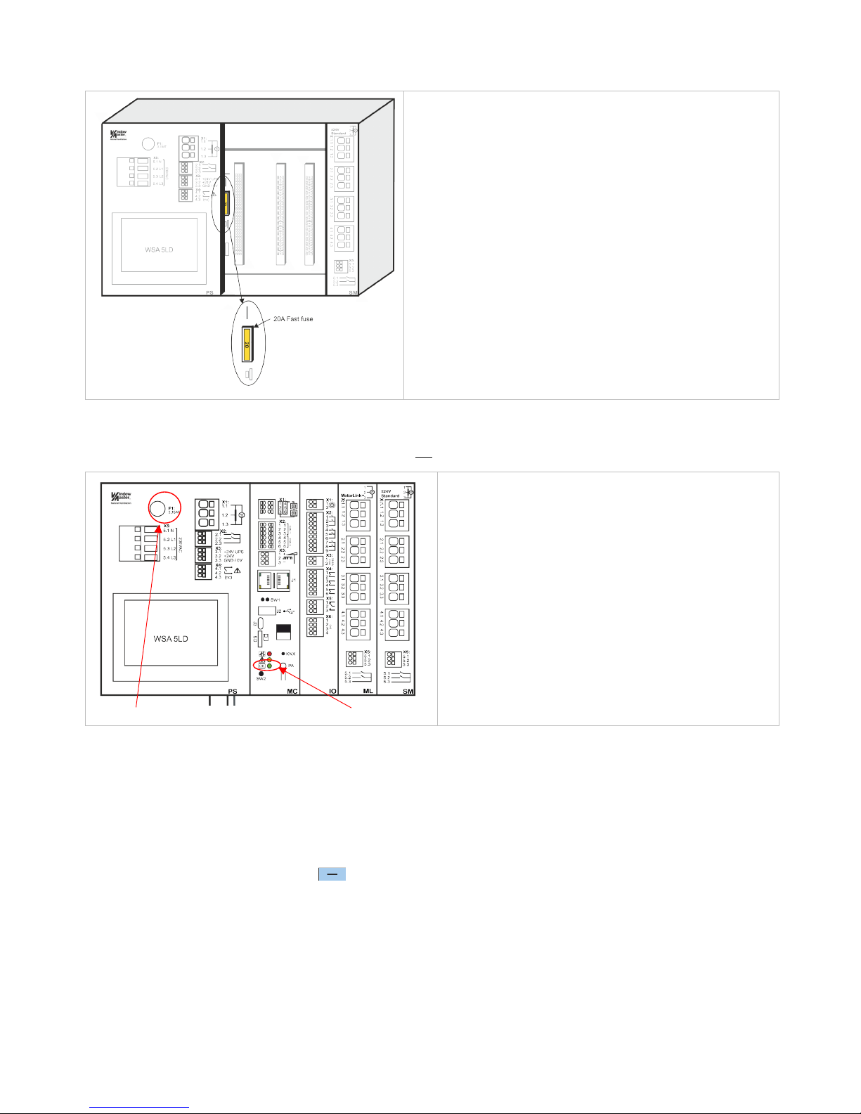
56
18.1.1 Blown fuse – 20A fast
Additionally, an error on the ”Battery status” can also be triggered if the fuse (20A fast) is blown.
Location of 20A fast fuse
The fuse is located behind the modules. To replace the fuse it is
therefore necessary to remove the modules, see section 23.2 for
replacement of modules.
18.1.2 Blown fuse – 3.15A slow
If there seems to be no sign of function in the smoke paken AND the green LED is not working either, it can be caused by a blown
3.15A slow fuse. The fuse is only blown if the green LED does not shine.
Location of 3.15A slow fuse Green LED
The slow fuse is located on the top part of the power supply
module.
The green LED is located in the bottom part of the overall
control module.
Both fuses are common fuses and can be purchased in by distributors of electronics.
19 Manage another WSA MC module – main menu
It is possible to operate more sections (up to 31 sections) from the same touch screen.
The function is used if the operation of several sections in one panel (WSC 540 or WSC 560) is to done on the same touch screen
or if more panels connected via CAN are to be operated from the same touch screen.
Select the section(s) that is (are) to be operated from this touch screen.
The touch screen changes to green when you operate another selected section.
To return to the master touch screen: press or press the number of the master touch screen.
You can still/also operate the sections on their own touch panels.
Page 57
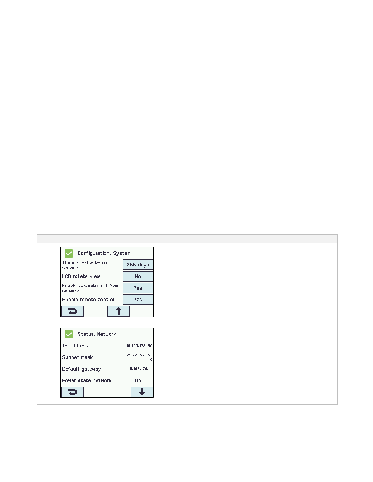
57
20 View all details – main menu
To make the configuration of the smoke ventilation panel as simple as possible during configuration (see chapter 13), it is only
possible to configure the most used functions.
Under 'View all details' is displayed all of the above functions together with detailed functions that are not used as often, but are
possible to configure.
If you are logged into access level 3 it is also possible to configure from this menu.
It is possible to view all details for:
Motor line
Motor group
Break glass unit
Smoke zone
Local input
Local output
Weather station type
Power supply
CAN
Network
KNX bus
BACnet
Log in
Configuration files, SD
Configuration files, USB
System
21 Remote control of FlexiSmoke™
It is possible to remote control a FlexiSmoke™ from a PC.
When the FlexiSmoke™ is on a standard computer network (Ethernet) you can from any PC with the “WMaFlexiSmokeRemote”
program control the FlexiSmoke™ just like if you were standing in front of the panel.
The program ”WMaFlexiSmokeRemote” program can be downloaded from our webpages (www.windowmaster.com) under
FlexiSmoke™.
Remote control can be configured in:
Configuration of remote control
To enable remote control of the panel it is necessary to allow
remote control. This is done in the configuration of the system.
Identification of the IP-address
IP-address of the FlexiSmoke™
Page 58
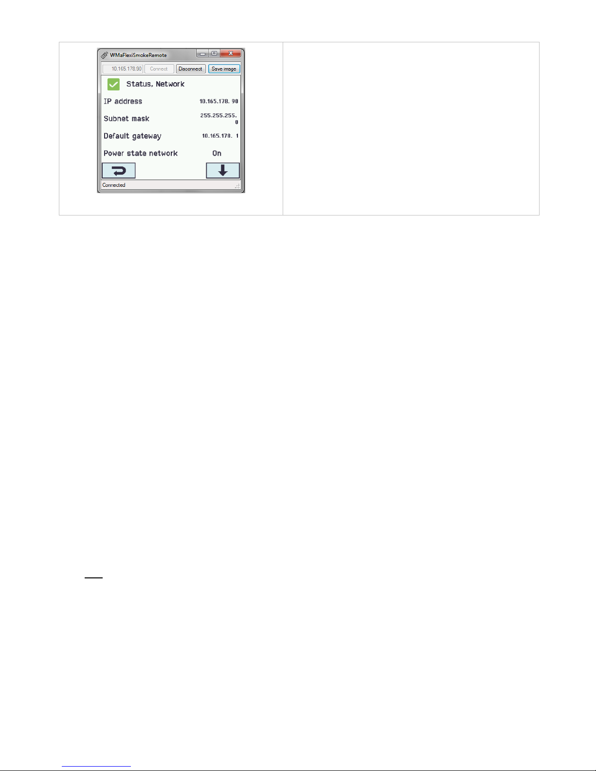
58
Screen shot from the PC when controlling
the FlexiSmoke™ remotely
Start the ’WMaFlexiSmokeRemote’ program on the connected PC.
Enter the IP-addressen and press ’Connect’.
22 Commissioning and test run
In case of hardware error please see chapter 17 “The menu ‘Hardware error’”
The break glass unit WSK 50x will only give an acoustic fault signal if the door on the break glass unit is closed or if the door
contact on the break glass unit is pressed.
We recommend that the software of the panel is updated during the annual maintenance check!
We recommend that the commisionin gof the smoke panel should be done by a competent smoke ventilation controls installer.
22.1 The control ventilation panel is completely installed, without the
operating voltage applied
a) Check all mechanical and electrical components for damage.
b) When more panels are connected via CAN, check the DIP slide switches in the sections in the smoke control panel for their
correct (required) position. See section 10.2 – WSA 5MC overall control module.
c) Check all screw and plug connections for tightness and/or firm seating
d) Check that all external components are installed:
1) ±24V actuators: Is the motor end module inserted in the last or only actuator?
2) Automatic smoke detectors: Is the passive end module inserted in the last or only smoke detector?
22.2 With mains voltage, without accumulator
Adhere to the relevant regulations! Connect the mains cables and reapply the mains voltage.
22.3 With mains voltage, with accumulator
a) Remove the protection film from one face of the supplied foam rubber. Glue each foam rubber to the bottom side of the
accumulators. Connect the accumulators to the black accumulator bridge according to the wiring diagram, then connect the red
and the black connection cable to the red and the black flat plug. Remove the bottom protection film of the foam rubber and
insert the batteries in the smoke ventilation panel according to section 11, and firmly press down to the housing bottom!
b) Plug the red connection cable to the + and the black connection to the flat plug of the control panel.
Note: Check correct polarity!
c) The smoke ventilation panel can now be configured as described in chapter 13 “The menu ‘Configuration’”
22.4 Ventilation keypad
Closely observe the motors during opening and closing. They must not be impaired in any position by the building structure.
Observe that the motor cables are not being subject to pulling or pinching.
Check each ventilation keypad individually.
22.5 Break glass unit WSK 50x
a) Open the door and press the red Open button. The actuators move open through to the end position. The red alarm LED (also
in the control panel) is ON; at the same time a permanent acoustic signal sounds (door contact on the break glass unit is
pressed!).
b) Press the Reset/Closed button in the break glass unit. The actuators close through to the end position. The comfort ventilation
function is released again. The red alarm LED (also in the smoke ventilation panel) and the acoustic smoke alarm are turned
off.
Page 59

59
22.6 Smoke detectors
a) Spray test aerosol on the smoke detectors (aerosol item no. 9549).
b) The actuators move open through to the end position. The red LED in the smoke detector, the red alarm LED (also in the
smoke ventilation panel) and the permanent acoustic signal in the break glass unit are ON.
c) Press the Reset/Closed button in the break glass unit - the actuators close through to the end position. The comfort ventilation
function is released again. The red alarm LED in the break glass unit and in the smoke control panel as well as the acoustic
smoke alarm are turned off.
22.7 Emergency power supply test
a) Remove the mains fuse from each section of the smoke ventilation panel. Wait 10 minutes (or run the motors shortly). See also
national guidelines.
b) When a mains error have occurred the green LED in the break glass units will flash for 30 minutes. The green LED on the WSA
5MC module in the smoke ventilation panel is still on and the yellow LED is turned off.
c) After 30 minutes the green LEDs will turn off and all the yellow LEDs in the smoke ventilation panel and the break glass units
will lit continuously.
d) The comfort ventilation keypads are deactivated.
e) Test the SHE trip and reset/closed as described under section 20.5.
f) Refit the mains fuse.
g) The green mains and operating LED's are on, the yellow LED is off, the malfunction message at the break glass unit is off.
22.8 Wind/rain detector
a) Open the actuators with the comfort ventilation keypads.
b) Wet the rain sensor, the actuators will fully close.
c) While the actuators are running, press the Open button at the keypad. The actuators must neither open nor stop!
Exception: If set as in point 13.2.3.8 to a manual override time (Man. operation after auto comm.).
d) The SHE trip has priority.
e) While the rain sensor is active (wet) the smoke ventilation panel is activated (alarm) and the actuators move open through to
the end position (alternatively to the SHE position)
If the start-up was successful, close the doors of the break glass units and of the smoke ventilation panel.
If the start-up was unsuccessful (error with one of the test run processes), please see chapter 10 “Description of modules”.
If necessary, check the wiring in accordance with the cable plan – see chapter 9 “Cable plan for connection to
WSC 520 / 540 / 560”.
23 Maintenance
The panels of the smoke detection and heat extraction system have to be checked, serviced and, if necessary, repaired at least
once per year by the manufacturer or an authorized system.
Remove all soiling from the units of the smoke and heat extraction system. Check fastening and clamping screws for firm seating.
Carry out a test run of the entire system (see chapter 20 ‘Commissioning and test run).
Only have defective units repaired in our factory. Only install original spare parts.
Check the operational condition at regular intervals. We recommend a WindowMaster service contract is taken out to ensure the
right function of the smoke and heat extraction system.
All back up batteries coming with the smoke control panel as standard; have to be subjected to regular checks.
The smoke ventilation panel will signal fault on the batteries if:
1. The battery voltage is below 17V
2. The charging current after 24 hours of charge is not below 100 mA. That is, if the battery voltage cannot be sufficiently high.
Within the framework of the service, the batteries have to be replaced after the specified maximum 4 year operating period.
Dispose of used batteries according to the National regulation.
CAUTION: RISK OF EXPLOSION IF BATTERIES ARE REPLACED BY AN INCORRECT TYPE.
We recommend that the software of the panel is updated during the annual maintenance check!
The expected minimum lifetime for the FlexiSmoke™ is 10 years excluding the batteries, see above.
23.1 Maintenance agreements
Be aware that regular inspection of smoke ventilation systems is a legal requirement. The legislation requires that the smoke
ventilation system's owner inspects and tests the system once every year.
WindowMaster offer maintenance agreements for the smoke ventilation system and every year we inspect the complete system to
ensure it complies with the applicable legislation. Maintenance of the smoke ventilation system includes checking windows, window
actuators and emergency power and checking that triggering and control functions are fully functional.
Contact our service department for further information: telephone +44 1536 614 070 or [email protected]
Page 60

60
23.2 Replacement modules
23.2.1 Replacement of 5PS, 5IO, 5ML and 5SM modules
1. Disconnect the 230 V and the batteries.
2. Wait until the display has completely turned off before removing the module.
3. Insert the replacement module.
4. Turn on the 230 V and connect the batteries.
5. The system will be ready again after approx. 2 seconds.
23.2.2 Replacement of 5MC module
1. Save a backup of the configuration on a USB stick (recommended) or the build in SD-Card and make a note of the CAN-address, if
necessary please see section 14.17 or 14.18.
2. Disconnect the 230 V and the batteries.
3. Wait until the display has completely turned off before removing the module.
4. Insert the 5MC replacement module.
5. Insert the USB stick or the SD-card from the old 5MC module into the new module.
6. Turn on the 230 V and connect the batteries.
7. Enter the CAN-address
8. Load the parameters from the USB stick / SD card.
9. The system will be ready again after approx. 2 seconds.
If the 5MC module, which is to be replaced, is completely without function then do straight to point 2.
If there is no backup of the configurations, these are to be entered manually.
It is therefore recommended to take a backup, on a USB stick (recommended) or on the built in SD card, when the panel is running, if
necessary please see section 14.17 or 14.18.
24 Declaration of Conformity and CE certificate
The smoke ventilation panels are manufactured and tested accordingly to the European requirements.
The total system is not to be put into service until a declaration of conformity for the total system has been made.
The “Declaration of Conformity” and the EN certificate are supplied with panel as separate documents.
 Loading...