

Page 1

UK
+44 (0) 1536 614 070
Other markets
+45 4567 0300
www.windowmaster.com
WSC 3xx STANDARD install 1809-Firmware v132 - UK ©WindowMaster 2015, 2018 ®WindowMaster is a registred trademark used under the license by WindowMaster Group
WindowMaster International A/S, Skelstedet 13, DK-2950 Vedbæk
WSC 310 & WSC 320
Standard versions
Installation instruction
CompactSmoke™
(Version 1809 – from firmware version 1.32 (main card))
Save this installation instruction to the end user
Page 2

2
1 Safety information ........................................................................................................................................................ 3
1.1 Safety ................................................................................................................................................................ 3
1.2 230V AC ............................................................................................................................................................ 3
1.3 Back-up batteries .............................................................................................................................................. 3
1.4 Application ......................................................................................................................................................... 3
1.5 Cable routing and electrical connection ............................................................................................................. 3
2 Structure of the smoke panel ...................................................................................................................................... 4
3 Variants of panels ........................................................................................................................................................ 5
3.1 Max numbers of actuators per motor line and panel
............................................................................................. 5
4 Accessories and spare parts ...................................................................................................................................... 7
5 Technical data .............................................................................................................................................................. 7
6 Mounting ....................................................................................................................................................................... 9
7 Installation .................................................................................................................................................................... 9
7.1 Cable routing ..................................................................................................................................................... 9
7.2 Cables into housing ........................................................................................................................................... 9
7.3 Connection of safety earth wire and 230V AC ................................................................................................... 9
7.4 Installation of the break glass unit, ventilation keypad and smoke detector ...................................................... 9
7.5 Assembly instructions .......................................................................................................................................10
8 Cable dimensioning ................................................................................................................................................... 10
8.1 Maintaining the cable functions ........................................................................................................................10
8.2 Max. cable Length ............................................................................................................................................10
8.2.1 Formula for the calculation of the maximum actuator cable length ............................................................. 10
8.2.2 Max cable length – ±24V standard actuators .............................................................................................. 11
8.2.3 Max cable length – actuators with MotorLink® ............................................................................................. 11
9 Cable plan for connection to WSC 310 / 320 Standard version ............................................................................. 12
10 Description of cards and mains connection ............................................................................................................ 13
10.1 WSC 310 mains connection and power supply (WCA 3P1) .............................................................................13
10.2 WSC 320 mains connection and power supply (WCA 3P2) .............................................................................13
10.3 Main control card WCA 3SS – Standard Version .............................................................................................14
11 DIP switch configuration ........................................................................................................................................... 20
12 Back-up batteries ....................................................................................................................................................... 21
13 Configuration of panel ............................................................................................................................................... 21
13.1 Motor lines – motor groups – smoke zones ......................................................................................................21
13.1.1 Assigned components per smoke zone ....................................................................................................... 22
13.1.2 Examples with motor lines / motor groups / smoke zones ........................................................................... 22
13.1.3 Motor line .................................................................................................................................................... 22
13.1.4 Smoke zone ................................................................................................................................................ 22
13.1.5 Local input ................................................................................................................................................... 23
13.1.6 Local output ................................................................................................................................................. 23
14 Fault detection via LED.............................................................................................................................................. 23
14.1 Fault detection on the smoke panel..................................................................................................................23
14.2 Fault indication on break glass unit ..................................................................................................................25
15 Hardware error ........................................................................................................................................................... 25
15.1 Error on the Power supply ................................................................................................................................25
15.1.1 Blown fuse – 20A fast .................................................................................................................................. 25
16 Commissioning and test run ..................................................................................................................................... 25
16.1 The control ventilation panel is completely installed, without the operating voltage applied .............................26
16.2 With mains voltage, without accumulator .........................................................................................................26
16.3 With mains voltage, with accumulator ..............................................................................................................26
16.4 Ventilation keypad ............................................................................................................................................26
16.5 Break glass unit WSK 50x ................................................................................................................................26
16.6 Smoke detectors ..............................................................................................................................................26
16.7 Emergency power supply test ..........................................................................................................................26
16.8 Wind/rain detector ............................................................................................................................................26
17 Maintenance ............................................................................................................................................................... 27
17.1 Maintenance agreements .................................................................................................................................27
17.2 Replacement 3SS card ....................................................................................................................................27
18 Declaration of Conformity and Declaration of Perfomance.................................................................................... 27
Page 3

3
1 Safety information
1.1 Safety
Only allow correspondingly trained, qualified and skilled personnel to carry out installation work.
Reliable operation and the avoidance of damage and hazards are only guaranteed if installation and settings are carried out
carefully in accordance with these instructions.
There may be personal danger by electrically operated windows:
- the forces occurring in the automatic mode can be such that parts of the body could get crushed
- when opened, actuators (spindles) could protrude into the room
For this reason, measures have to be taken prior to starting up the actuators, which exclude the danger of injury.
For safety reasons we recommend to install opening restrictors on bottom-hung windows.
In the event that windows are subjected to rain and/or high wind loads, we recommend connecting a wind/rain sensor to the
smoke ventilation panel for the automatically closing of the windows.
The smoke ventilation panel is to be located in a safe place, protected from the effects of fire and smoke.
The smoke ventilation panel is to be surface mounted.
The smoke ventilation panel has two energy suppliers: 230V AC and back-up batteries.
The manufacturer does not assume any liability for possible damage resulting from inappropriate use.
1.2 230V AC
230V AC can cause death, severe injury or considerable damage to assets.
The connection of the smoke ventilation panel is reserved for qualified personnel.
Disconnect all poles of the panel from the supply voltage prior to opening, installation or assembling.
Installation and use according to the national regulations.
1.3 Back-up batteries
Back-up batteries 2 batteries per panel can cause severe injury or considerable damage to assets.
The connection of the smoke ventilation panel is reserved for qualified personnel.
Disconnect all poles of the panel from the back-up batteries prior to installation or assembling.
Ensure that the mains cable can be switched via an external or customer-supplied two-pole switch element or a switch element
controlling all poles – see section 7.1 “Cable routing”
Installation and use according to the National regulations.
Dispose of used batteries according to the National regulation.
CAUTION
RISK OF EXPLOSION IF BATTERIES ARE REPLACED BY AN INCORRECT TYPE.
1.4 Application
The smoke ventilation panel is exclusively designed for the automatic opening and closing of smoke extraction systems,
windows, flaps or doors.
Always check that your system meets the valid national regulations.
Pay particular attention to the opening cross section, the opening time and opening speed.
The cable cross sections depend on the cable length and current consumption (amperage).
1.5 Cable routing and electrical connection
Fuse the 230V AC power supply cable separately on site.
Cable routing and connection - adhere to national regulations.
Establish the cable types, if necessary, with the local approval bodies or the fire protection authority.
Do not conceal flexible cables.
Junction box must be accessible for maintenance purposes.
Disconnect all poles of the mains voltage and the back-up batteries prior to starting maintenance work or making changes to the
system.
Secure the system to prevent unintentional switching on again.
Route all low voltage cables (24V DC) separate from the power current cables.
Design cable types, lengths and cross sections in accordance with the technical information.
Cable specifications is a guide only, the overall responsibility resides with the electrical contractor on site.
Installation must be in accordance with the national electrical regulations.
Page 4
4
2 Structure of the smoke panel
Sizes & Versions
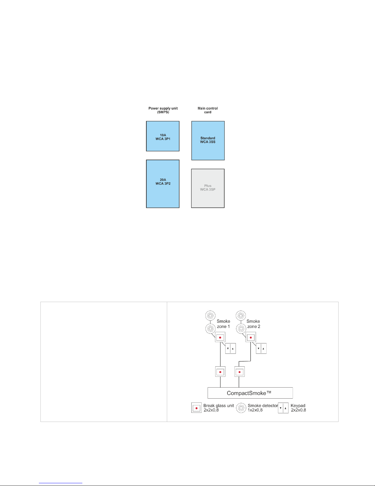
The WSC 310 and WSC 320 smoke ventilation panels are available in two different versions namely a Standard and a Plus
version. This installation instruction only deals with the Standard versions. Please see separate installation instruction for the
Plus versions of WSC 310 and WSC 320.
Cards
Each panel contains a power supply unit (SMPS), either a WCA 3P1 or a WCA 3P2 for the 10A or 20A version respectively.
Aside from the power supply unit the Standard version also includes a main control card type WCA 3SS.
If additional motor lines, inputs or fieldbus connection is required a Plus version of the panel is necessary.
The Main control card type WCA 3SS allows connections of 2 motor lines and 2 keypads.
Motor groups and motor lines
A motor group consists of one or more motor lines and all the motor lines are operated simultaneously.
Both motor lines on the main control card (WCA 3SS) can be configured for either a ±24V standard actuators or MotorLink®
actuators. A motor group can contain motor lines with both ±24V standard actuators and MotorLink® actuators, whereas a motor
line only can have ±24V standard or MotorLink® actuators connected.
Break glass unit
Break glass unit type WSK 50x are to be used together with WSC 310/320. The number of smoke zones is determined by the
number of inputs to which break glass units are connected. On the Standard version max 2 smoke zones are possible.
Inputs
Cabling
The WSC 3xx CompactSmoke™ uses bus
technology and the overall cabling for break
glass units, smoke detectors and keypads is
significantly reduced compared to other types of
smoke panels.
The main control card has 1 input for a smoke
detector, 2 inputs for break glass units (where
up to 10 break glass units can be connected)
and 2 inputs for ventilation keypads (no max
number of keypads).
Smoke detectors are either connected to the
smoke detector input or to a break glass unit
(type WSK 501 / 502).
The panel can have up to 2 smoke zones and 2
motor groups.
Page 5
5
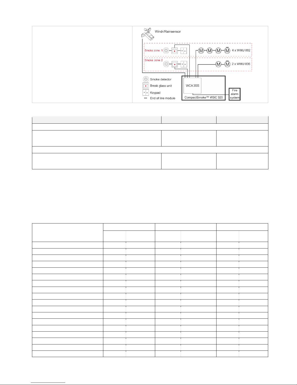
System example with
WSC 320
Smoke ventilation panel (20A) with 2 smoke
zones.
The keypads and smoke detectors are cabled
directly to the break glass units in the smoke
zones, which means that the need for cabling in
the building is significantly reduced.
A wind/rain sensor is connected to close the
windows during comfort ventilation in case of
high wind and/or rain.
The smoke ventilation panel is connected to the
Fire Alarm System via the WCA 3SS card.
3 Variants of panels
Number of motor lines and other functions
Cards
Item number
WSC 310
Standard version
2 motor lines
2 keypads / inputs
No cards
WSC 310 S 0202 E1
WSC 320
Standard version
2 motor lines
2 keypads / inputs
No cards
WSC 320 S 0202 E1
The standard version of the panels have 16 DIP switches for easy configuration of the panel, see section 11 for further
information.
3.1 Max numbers of actuators per motor line and panel
The table shows the maximum number of actuators, which can be connected per motor line and panel depending on the type of the
actuators, panel and connected cards. The total power consumption of all the connected actuators must not exceed 10A or 20A
depending on panel size.
WSC 320 with 20A includes up to two motor lines each with 10A. If there is a need of more than 10A on one motor line, DIP switch
2.6 is set to 20A. Hereafter one motor line can be loaded with 20A or two motor lines can loaded up to a total of 20A e.g. 17A and
3A.
Per Motor line
Per 10A Panel
Per 20A Panel
± 24V
Actuator
MotorLink®
Actuator
± 24V
Actuator
MotorLink®
Actuator
± 24V
Actuator
MotorLink®
Actuator
WMS 306-1
10 4 10 8 20
8
WMS 306-2
10 2 10 4 20
4
WMS 306-3 9 3 9 6
18
6
WMS 306-4 8 4 8 8
20
8
WMS 309-1
10 4 10 8 20
8
WMS 309-2
10 2 10 4 20
4
WMS 309-3 9 3 9 6
18
6
WMS 309-4 8 4 8 8
20
8
WMS 409 xxxx 01
5 0 5 0 10
0
WMS 409-1 5 4 5 4
10
8
WMS 409-2 4 2 4 4 8 4
WMS 409-3 3 3 3 3 9 6
WMS 409-4 4 4 4 4 8 8
WMS 515 2 0 2 0 4 0
WMU 836-1
10 4 10 8 20
8
WMU 836-2
10 2 10 4 20
4
WMU 836-3 9 3 9 6
18
6
WMU 836-4 8 4 8 8
20
8
Page 6

6
Per Motor line
Per 10A Panel
Per 20A Panel
± 24V
Actuator
MotorLink®
Actuator
± 24V
Actuator
MotorLink®
Actuator
± 24V
Actuator
MotorLink®
Actuator
WMS 409-1 5 4 5 4
10
8
WMS 409-2 4 2 4 4 8 4
WMS 409-3 3 3 3 3 9 6
WMS 409-4 4 4 4 4 8 8
WMS 515 2 0 2 0 4 0
WMU 836-1
10 4 10 8 20
8
WMU 836-2
10 2 10 4 20
4
WMU 836-3 9 3 9 6
18
6
WMU 836-4 8 4 8 8
20
8
WMU 861-1 6 4 6 6
12
8
WMU 861-2 6 2 6 4
12
4
WMU 861-3 6 3 6 6
12
6
WMU 861-4 4 4 4 4
12
8
WMU 842 / 862 / 882-1
4 4 4 4 8
8
WMU 842 / 862 / 882-2
4 2 4 4 8
4
WMU 842 / 862 / 882-3
3 3 3 3 6
6
WMU 842 / 862 / 882-4
4 4 4 4 8
8
WMU 863 / 883-1
3 3 3 3 6
6
WMU 863 / 883-2
2 2 2 2 6
4
WMU 863 / 883-3
3 3 3 3 6
6
WMU 863 / 883-4
0 0 0 0 4
4
WMU 864 / 884-1
2 2 2 2 4
4
WMU 864 / 884-2
2 2 2 2 4
4
WMU 864 / 884-3
0 0 0 0 3
3
WMU 864 / 884-4
0 0 0 0 4
4
WMU 885 / 895-1
2 2 2 2 4
4
WMU 885 / 895-2
2 2 2 2 4
4
WMU 885 / 895-3
0 0 0 0 3
3
WMU 885 / 895-4
0 0 0 0 4
4
WMX 503 / 504 / 523 / 526-1
20 4 20 8 40
8
WMX 503 / 504 / 523 / 526-2
20 2 20 4 40
4
WMX 503 / 504 / 523 / 526-3
18 3 18 6 39
6
WMX 503 / 504 / 523 / 526-4
20 4 20 8 40
8
WMX 803 / 804 / 823 / 826-1
10 4 10 8 20
8
WMX 803 / 804 / 823 / 826-2
10 2 10 4 20
4
WMX 803 / 804 / 823 / 826-3
9 3 9 6 18
6
WMX 803 / 804 / 823 / 826-4
8 4 8 8 20
8
WML 820/825
10 0 10 0 20
0
WML 860-1
10 4 10 8 20
8
WML 860-2
10 2 10 4 20
4
WML 860-3 9 3 9 6
18
6
WML 860-4 8 4 8 8
20
8
WMB 801/802*
max. 4A connected to the WMB
WMB 811/812 */**
10 2 10 4 20
4
* Do not exceed the total power consumption of the motor line
** When having two locking actuators per motor line, it must be one of each type: 1 x WMB 811 and 1 x WMB 812
Page 7
7
4 Accessories and spare parts
Accessories
Back-up battery for WSC 310 - 7Ah (2 x WSA 007 per panel )
WSA 007
Back-up battery for WSC 320 - 12Ah (2 x WSA 012 per panel)
WSA 012
Break glass unit, primary, with data communication, PVC housing. With input for smoke detector and
comfort keypads. Only one unit per line.
x = colour of the housing: 1=red, 2=yellow, 3=grey, 4=blue, 5=orange
WSK 501 000x
Break glass unit, primary, with data communication, metal housing. With input for smoke detector and
comfort keypads. Only one unit per line.
x = colour of the housing: 2=yellow, 3=grey, 5=orange
WSK 502 000x
Break glass unit, primary, with data communication, PVC housing. No input for smoke detector or
keypad. Max five units per line.
x = colour of the housing: 1=red, 2=yellow, 3=grey, 4=blue, 5=orange
WSK 503 000x
Break glass unit, primary, with data communication, metal housing. No input for smoke detector or
keypad. Max five units per line.
x = colour of the housing: 2=yellow, 3=grey, 5=orange
WSK 504 000x
Smoke detector
WSA 300
Rain sensor
WLA 331
Rain/wind speed sensor
WLA 330
End of line motor module
WSA 510
End of line smoke detector module (10kΩ resistor), 10 pcs.
WSA 501
Cables for smoke ventilation – see separate data sheet for further information
WLL 8xx
Spare parts
10A power supply unit for WSC 310
WCA 3P1
20A power supply unit for WSC 320
WCA 3P2
Main control card for Standard version WSC 310 / WSC 320 incl. cover + 2 end of line modules
(WSA 510)
WCA 3SS
Plastic cover for the main control card in the WSC 310 / WSC 320 Standard version
WCA 302
Lock cylinder incl. 2 keys for WSC 310/320 panel
WCA 307
Replacement glass for break glass units type WSK 501 / 502 / 503 / 504, 5 pcs.
WSK 397
Keys for break glass units type WSK 501 / 503, 5 pcs.
WSK 398
Keys for break glass units type WSK 502 / 504, 1 pcs.
WSK 453
Lockable replacement PVC housing for break glass unit
x=colour of the housing: 1 = red, 2 = yellow, 3 = grey, 4 = blue, 5 = orange
WSK 399 000x
Back-up battery cable kit for WSC 310 / 320 (cable between WCA 3SP / 3SS and the batteries and
between the batteries)
WSA 330 0101
20A battery fuse. The battery fuse on the WCA 3SP/3SS, 10 pcs
WSA 331 0101
5 Technical data
Technical data
Output current (nominal)
WSC 310: 10A / WSC 320: 20A
Secondary voltage
Voltage 24V DC (±15%)
Open circuit voltage (no load) 27.6V DC @ 20°C
Ripple at max load max. 6% (3.5Vpp)
Motor lines
Motor groups
Smoke zones
2 motor lines – a line can be either ±24V standard motor line or MotorLink® motor
lines - in max 2 motor groups and max 2 smoke zones
Primary voltage
WSC 310: 230V AC, 50Hz (85-264V AC, 47-63Hz)
WSC 320: 230V AC, 50Hz (85-264V AC, 47-63Hz)
Page 8
8
Power consumption
WSC 310: min 3.2W
1+2
, typ. 4.8W
1+3
. At max load 300W
WSC 320: min 5.0W
1+2
, typ. 5.6W
1+3
. At max load 600W
1) no load: system operational but no actuators are running
2) min: 1 x break glass unit WSK 501 and 1 x smoke detector WSA 300
3) max load: 1 x break glass unit WSK 501, 4 x break glass unit WSK 503 and
10 x smoke detector WSA 300
Inrush current on primary site
70A<5ms
Max. 3 x WSC 310/320 per 10A supply group.
Circuit breaker “C” characteristic.
±24V change over time
min 500ms
Back-up batteries
WSC 310: 2 x WSA 007 (12V / 7Ah)
WSC 320: 2 x WSA 012 (12V / 12Ah)
Expected lifetime max 4 years, only use genuine WindowMaster batteries
Emergency power
>72 hours in accordance with EN 12101-10
Automatic smoke triggering
Smoke triggering when the temperature inside the compact unit exceeds 72ºC
Charging unit (integrated in WCA 3SS
card)
Charging voltage: 27.7 – 27.8V at 20ºC
Charging current: 1.7A, current limited
Priority
Smoke signal has always highest priority
Cable monitoring
±24V standard actuators with end of line module and smoke detectors are
monitored by closed-circuit
Actuators with MotorLink® and break glass units are monitored by data
communication
Back-up batteries are monitored by cyclic measuring
LED message OK, fault and alarm
Green
Yellow
Red
all OK
fault
fire
Reopening the actuators
Every 2.min. in 30min. after a SHE open (selectable) Pre-set: no reopening
Connection cable
Actuators
Other
components
flexible max 6 mm² / solide max 10 mm²
min 0,2mm² / max 1,5mm²
Operating conditions
-5°C - +40°C, max. 95% relative humidity (not condensing)
EN 12101-10: Operation class A, Environmental class 1, with IP value increased
to IP 54 (according to EN 12101-10 is min. IP 30 required)
Max actuator activation duration (duty
cycle)
ED 40% (4min. per 10min.)
Max allowed current drawn from the
battery when the primary power
source is disconnected
WSC 310: 10A
WSC 321: 20A
Max interruption time during switching
between power sources
<2.0sec
Break glass unit
Up to 10 break glass units type WSK 50x can be connected to the WCA 3SS, but
only 1 WSK 501 / 502 per line, meaning max 2 WSK 501 / 502 per panel.
Smoke detectors and ventilation keypads can only be connected to the break
glass units type WSK 501 / 502.
Up to 10 smoke detectors can be connected to each WSK 501 / 502, and 10
smoke detectors can be connected to the smoke detector input on the main
control card, which give a total maximum of 30 smoke detectors.
There is no limit on the number of ventilation keypads connected to the WSK 501
/ 502.
Smoke detectors and ventilation keypads cannot be connected to WSK 503 /
504.
Number of motor lines
2 x 10A motor line for ±24V standard or MotorLink® actuators
Material
Metal housing for surface mounting
Colour
Grey (RAL 7035)
Page 9
9
Size
WSC 310: 300 x 400 x 120mm (HxWxD)
WSC 320: 300 x 400 x 210mm (HxWxD)
Weight
WSC 310: 6kg no batteries, 10.8kg with batteries (2 x WSA 007)
WSC 320: 8.6kg no batteries, 16.6kg with batteries (2 x WSA 012)
Protection class
IP 54
Approval / certification
Approved and certified according to EN 12101-10
Delivery
CompactSmoke™ smoke ventilation panel with WSA 501 (10kΩ resistors, 10
pcs.) and 2 pcs. end of line module WSA 510. Back-up batteries included.
Note
We reserve the right to make technical changes
6 Mounting
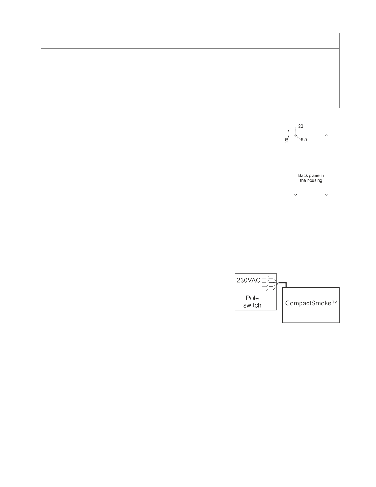
The smoke ventilation panel is fixed to the wall through the Ø8.5mm holes in the back plane of the
housing.
If the panel is fixed in different way, the holes are to be blinded with the 4 blind grommets, this way
the IP class is maintained.
The door is turnable.
When turning the door also move the blind grommets to the new holes.
The smoke ventilation panel is to be located in a safe place, protected from the effects of fire and
smoke.
7 Installation
7.1 Cable routing
For cable routing we recommend the use of fire protected cables retaining their function E90 or E30.
See also chapter 8 “Cable dimensioning” in this instruction.
However, this has to be agreed with the Engineer or, if necessary, with the local fire protection department.
Do not reduce the cable cross sections specified in the cable lengths table.
All cables of the control (except the mains supply cable) carry 24V DC and have to be routed separate from the mains supply
cable.
Adhere to the pertinent national and local regulations when routing the cables.
Lead the connection cables into the housing of the control panel from above
and the cable glans shall comply with fire class V-1 (IEC/EN 60695-11-20 / UL
94) or higher and be in accordance with national and local regulations.
Ensure that the mains cable can be switched via an external or customer-supplied
two-pole switch element or a switch element controlling all poles – see drawing.
7.2 Cables into housing
All connection terminals (except the mains terminals) are of the plug-in type.
Connect the connection cables in accordance with the terminal plan. Ensure that the connections are made correctly.
Incorrect cable clamping, mixing up numbers or colours could lead to malfunctions of the control panel or of the external
components.
Ensure that the electrical cables are always routed according to the valid national and local regulations.
7.3 Connection of safety earth wire and 230V AC
See chapter 10 ‘Description of cards’, section 10.1 for further description.
7.4 Installation of the break glass unit, ventilation keypad and smoke detector
Ensure that the break glass unit and the ventilation buttons are visible and well accessible. Do not install behind protruding
walls, door panels or hidden by the building structure.
Note: Installation height of the break glass unit 1.5 – 1.7m above floor.
Install the smoke detectors in accordance with their enclosed instructions
Page 10

10
7.5 Assembly instructions
Always have assembly, installation, repair and maintenance of smoke and heat extraction systems carried out by
qualified personnel trained for this purpose.
Rules to be adhered to for setting up and installation
The following safety relevant rules have to be adhered to when planning the use of a smoke and heat extraction system and its
set-up and installation:
• The Provincial Building Ordinance of the provinces,
• The regulations of the competent fire protection authority,
Accident prevention regulations
Adhere to the general accident prevention regulations (APR), the APR for power operated windows and doors, and the
installation rules in your country.
CAUTION:
Live components are directly accessible after opening the system housing.
Prior to inserting / removing cards disconnect to the panel from the mains supply and the back-up batteries.
• adhere to the installation instructions and your local energy providers
• select the place of installation such that free access is guaranteed for maintenance purposes
• select cables according to regulations in this instruction - take the calculation of the actuator supply cable lengths
into account when laying the cables
• power cables entered via the cable glands
• connect the cables in accordance with the drawings provided by the manufacturer
• route the cables in the building according to the regulations in this instruction
• after the smoke panel is installed the back-up batteries will be fully charged after ca. 8 hours
• check all system functions
Electric cable routing for smoke and heat extraction systems
Electrical cables always have to be laid in accordance with the national and local rules in your country.
Do not use the PE wire / green/yellow wire!
Cables of type NYM, concealed, can be used.
For surface laying, halogen free safety cables are recommended (see cable plan).
If possible, the use of cable types should be agreed with the Technical Services and the competent fire protection authority.
For the maximum permissible cable lengths of the actuator supply cables for the WSC 3xx system, taking the specified cable
cross sections into account (cable information for surface laying), please refer to chapter 8 “Cable dimensioning”.
8 Cable dimensioning
8.1 Maintaining the cable functions
According to valid national regulations.
The cable network for smoke ventilation systems (“Cable system“) ends normally at the interface (junction box) for the actuator!
The flexible, heat resistant connection cable of actuator is part of the system component‚ electric actuator actuation, and is not a
part of the electrical installation!
We recommend in all cases to discuss the type of cable routing with the competent fire fighting authorities.
8.2 Max. cable Length
Maximum permissible cable length from the smoke ventilation panel to the actuators and pyrotechnic gas generator taking into
account the cable cross-section is shown in the following tables for “± 24V standard actuators“, “MotorLink® actuators“ and
pyrotechnic gas generator.
8.2.1 Formula for the calculation of the maximum actuator cable length
Max. cable length = permissible voltage drop 2V (UL) x conductivity of copper(56) x cable cross section in mm2 (a)
max. actuator current total in amps (I) x 2
For both ±24V standard actuators and actuators with MotorLink® the cross section of the cable must not be less than 0.75mm2
regardless of the result of above formula.
Maximum actuator cable length: Always measured from the smoke to the last junction box
Permissible max. voltage drop in the line: 2 Volt
Actuating current: Sum of all actuator power consumption per motor line
Note: do not use the PE wire / green/yellow wire!
Example
Max actuator cable length with cable cross section 0.75mm2 and actuator current 2A: (2 x 56x0.75) : (2 x 2) = 21m
Page 11
11
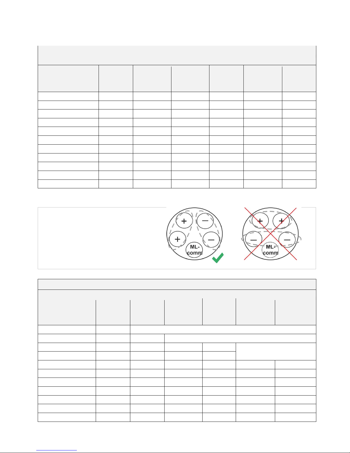
8.2.2 Max cable length – ±24V standard actuators
The actuator supply cable must have 3 wires: 2 wires current carrying / 1 wire for monitoring.
±24V standard Actuators
Do not use the PE wire / green/yellow wire!
cable cross
section [a]
Total
actuator current [I]
3 wire
0.75mm²
3 wire
1.50 mm²
5 wire
1.50 mm²
2 wire
parallel
3 wire
2.50 mm²
5 wire
2.50 mm²
2 wire
parallel
3 wire
4.00 mm²
1A
42m
84m
168m
140m
280m
224m
2A
21m
42m
84m
70m
140m
112m
3A
14m
28m
56m
47m
93m
75m
4A
11m
21m
42m
35m
70m
56m
5A
8m
17m
34m
28m
56m
45m
6A
7m
14m
28m
23m
47m
37m
7A
6m
12m
24m
20m
40m
32m
8A
5m
11m
21m
18m
35m
28m
9A
9m
18m
15m
31m
25m
10A
8m
16m
14m
28m
22m
20A
4m
8m
7m
14m
11m
8.2.3 Max cable length – actuators with MotorLink®
The actuator supply cable must have 3 wires: 2 wires current carrying / 1 wire for communication.
When a 5 wire cable is used for MotorLink®
It is not recommended to use parallel-wire.
ML-comm = MotorLink® communication
When using actuators with MotorLink® the max cable length is 50m regardless of the result of the above mentions formula.
Actuators with MotorLink®
Do not use the PE wire / green/yellow wire!
cable cross
section [a]
Total
actuator current [I]
3 wire
0.75mm²
3 wire
1.50 mm²
5 wire
1.50 mm²
2 wire
parallel
3 wire
2.50 mm²
5 wire
2.50 mm²
2 wire
parallel
3 wire
4.00 mm²
1A
42m
50m
2A
21m
40m
50m
3A
14m
28m
50m
47m
50m
4A
11m
21m
42m
35m
5A
8m
17m
34m
28m
50m
45m
6A
7m
14m
28m
23m
47m
37m
7A
6m
12m
24m
20m
40m
32m
8A
5m
11m
21m
18m
35m
28m
9A
9m
18m
15m
31m
25m
10A
8m
16m
14m
28m
22m
20A
4m
8m
7m
14m
11m
Page 12
12
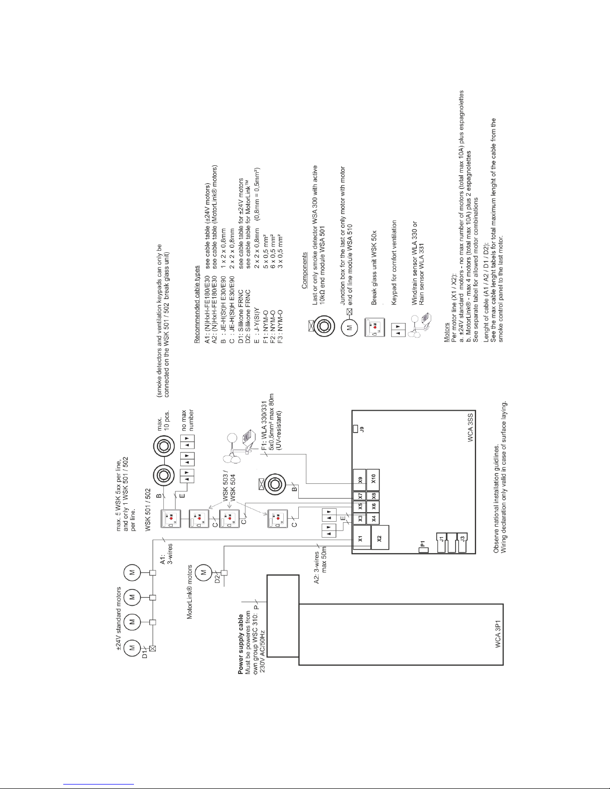
9 Cable plan for connection to WSC 310 / 320 Standard version
The above plan shows a WSC 310 panel, where the power supply unit is located in the left side of the panel wherefrom also mains
is pulled. The power supply unit for the WSC 320 panel is located underneath the main control card and mains is pulled from the
top right side. See section 10.1.
Page 13
13
10 Description of cards and mains connection
Each panel includes a power supply unit (SMPS) and a main control card.
The size of the power supply unit determines the size of the panel and the number and/or types of actuators, which can be
connected to the panel. See table with overview of max number of allowed actuators per motor line/panel (chapter 0).
The size of the power supply also determines the physical design of the panel inside the cabinet and thereby eg. where mains is
connected to the main control card (WCA 3SS).
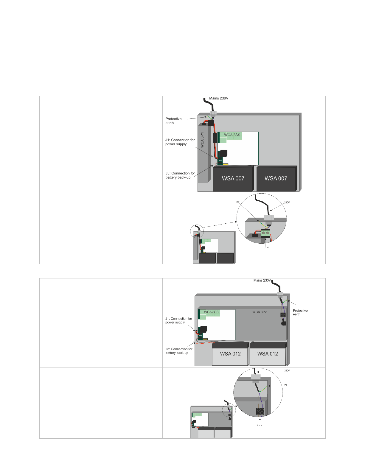
10.1 WSC 310 mains connection and power supply (WCA 3P1)
WSC 310 – WCA 3P1
With 300W SMPS unit
The power supply is located to the left of the main
control card.
The cable inlet is in the top left corner of the panel.
The panel must be grounded by means of protective
earth on the top panel plate.
Connection to mains.
10.2 WSC 320 mains connection and power supply (WCA 3P2)
WSC 320 - WCA 3P2
With 600W SMPS unit
The power supply is located underneath the main
control card.
The cable inlet is in top right corner of the panel.
The panel must be grounded by means of protective
earth on the top right side of the panel.
Connection to mains.
Page 14
14
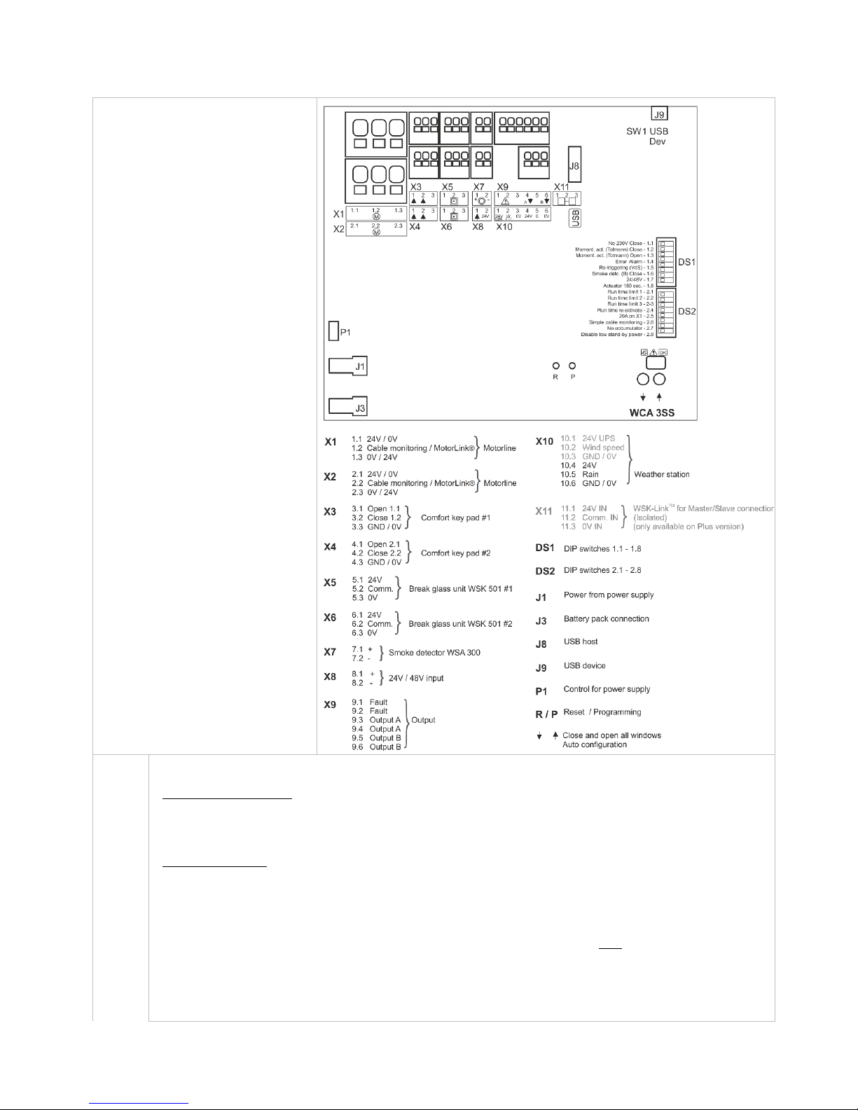
10.3 Main control card WCA 3SS – Standard Version
Each WCA 3SS contains the
following:
- 2 motor line for ±24V
standard or MotorLink® actuators
- 2 input for keypads for
comfort ventilation
- 2 input for break glass units
- 1 input for smoke detector
- 1 input for 24V/48V
- output for fault signal to Fire
Alarm System
- Input for weather station
(WLA 330 / 331)
- Connection of power supply
- Connection for battery back-up
- Connection for USB device
X1 / X2
The WCA 3SS card has 2 motor lines (X1 and X2) for connection of ±24V standard or MotorLink® actuators.
±24V standard actuators
1.1 24V / 0V
1.2 Cable monitoring
1.3 0V / 24V
2.1 24V / 0V
2.2 Cable monitoring
2.3 0V / 24V
MotorLink® actuator
1.1 0V
1.2 Communication
1.3 24V
2.1 0V
2.2 Communication
2.3 24V
The number of actuators per motor line depends on the actuator type, the total power consumption of actuators
connected to a motor line can max be 10A and the total max power consumption for both motor lines must not
exceed 10A or 20A depending on panel type.
Besides actuators also locking actuators (espagnolettes actuators) type WMB 801/802 and WMB 811/812 can
be connected. The power consumption of the locking actuators are not to be included in the 10A / 20A as
actuators and locking actuators do not run at the same time.
Page 15
15
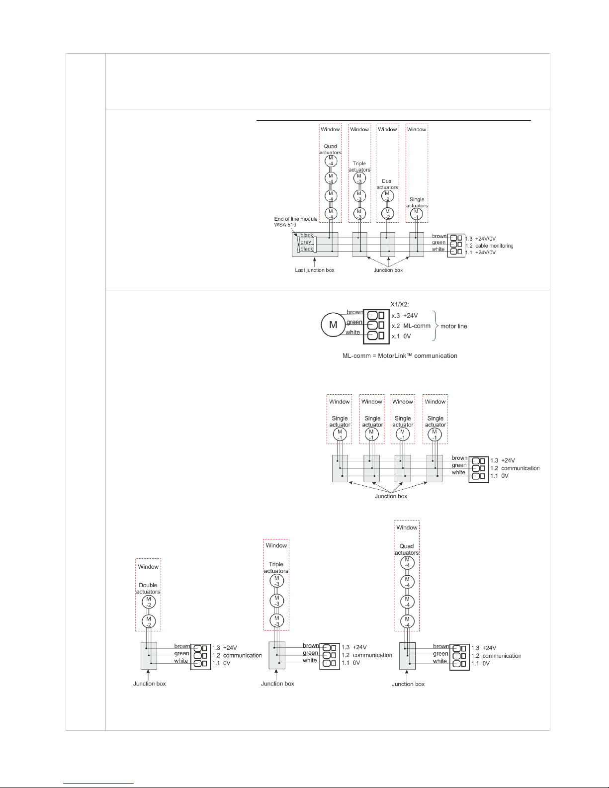
All actuators on the same motor line will run/be operated simultaneously.
All actuators on the same motor line must be of the same type.
Connection / cable diameter: flexible max 6 mm² / solid max 10 mm².
Cable length: see the chapter "Cable dimensioning".
Standard ±24V actuators
Examples with 20A power
consumption
a) 20 pcs. WMX 826-1
b) 10 sets of 2 pcs. WMX 826-2
c) 4 pcs. WMU 885-1
d) 2 sets of 2 pcs. WMU 885-2
Cable monitoring
When using ±24V standard
actuators or non-WindowMaster
actuators and cable monitoring is
wanted a 10kΩ resistor is used. An
“end of line motor module” type
WSA 510 must be added in the last
junction box. Actuator are per
default monitored.
Connection of standard actuators on motor line X1 (with cable monitoring)
MotorLink® actuators
Examples with actuators per
motor line
Ex. 1: 4 pcs. WMX 823-1
Ex. 2: 2 pcs. WMX 885-2
Ex. 3: 3 pcs. WMU 826-3
Allowed actuator combinations on a MotorLink® motor line
The two motor lines on the SS card can each be connected to one of the below shown combinations.
-1 (single): one window with one single window
actuator. Up to four windows each with one
single window actuator can be connected
-2 (double): one window with two double window
actuators.
-3 (triple): one window with three triple window
actuators.
-4 (quad): one window with four quad window
actuators.
Cable monitoring
When using actuators with MotorLink® the actuators with MotorLink® are monitored by data communication.
When the team-size does not match, an error is indicated on the diodes.
Page 16
16
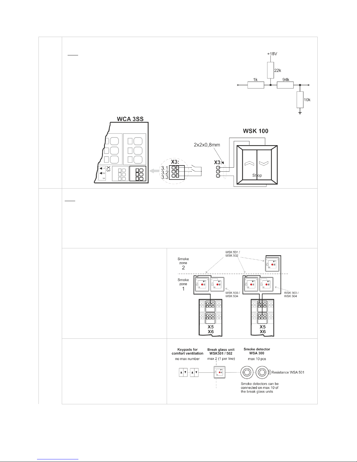
X3 / X4
For connection of comfort keypads.
With the default values are input:
”Active” if the contact resistance is smaller than 2kΩ
”Inactive” if the contact resistance is bigger than 3kΩ.
Input has pull up current of approx. 0.8mA. (min 0.7mA, max 1mA )
Example: comfort keypad connected to input X3
Data
3.1 Open
3.2 Close
3.3 GND / 0V
4.1 Open
4.2 Close
4.3 GND / 0V
X5 / X6
For connection of break glass unit type WSK 50x.
Data
Break glass unit bus 1
5.1 24V
5.2 Communication
5.3 0V
Break glass unit bus 2
6.1 24V
6.2 Communication
6.3 0V
Up to 5 break glass units type WSK 503 or WSK 504 can be connected to each line. If keypad and smoke
detector are to be connected to the break glass unit, WSK 501 or WSK 502 are to be used. Max one of these
break glass unit on each motor line, the remaining units (up to four) must be of type WSC 503 or WSC 504.
As the break glass units are monitored,
the connection of the break glass units
depends therefore of the number of
smoke zones.
Break glass unit must not be connected
in a ring bus.
Keypads and smoke detectors can also
be connected on the break glass unit
type WSK 501 / 502.
Per panel up to 10 break glass units can
be connected.
But only 2 of these 10 (one per line) can
be a type WSK 501 / 502 to which
keypads or smoke detectors can be
connected. The remaining break glass
units must be type WSK 503 / 504.
Open circuit (simplified)
Page 17
17
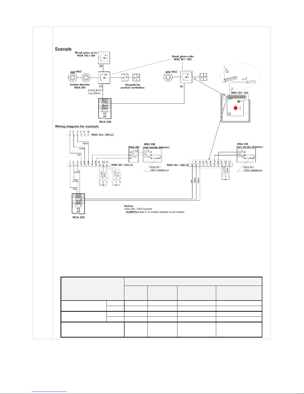
Example:
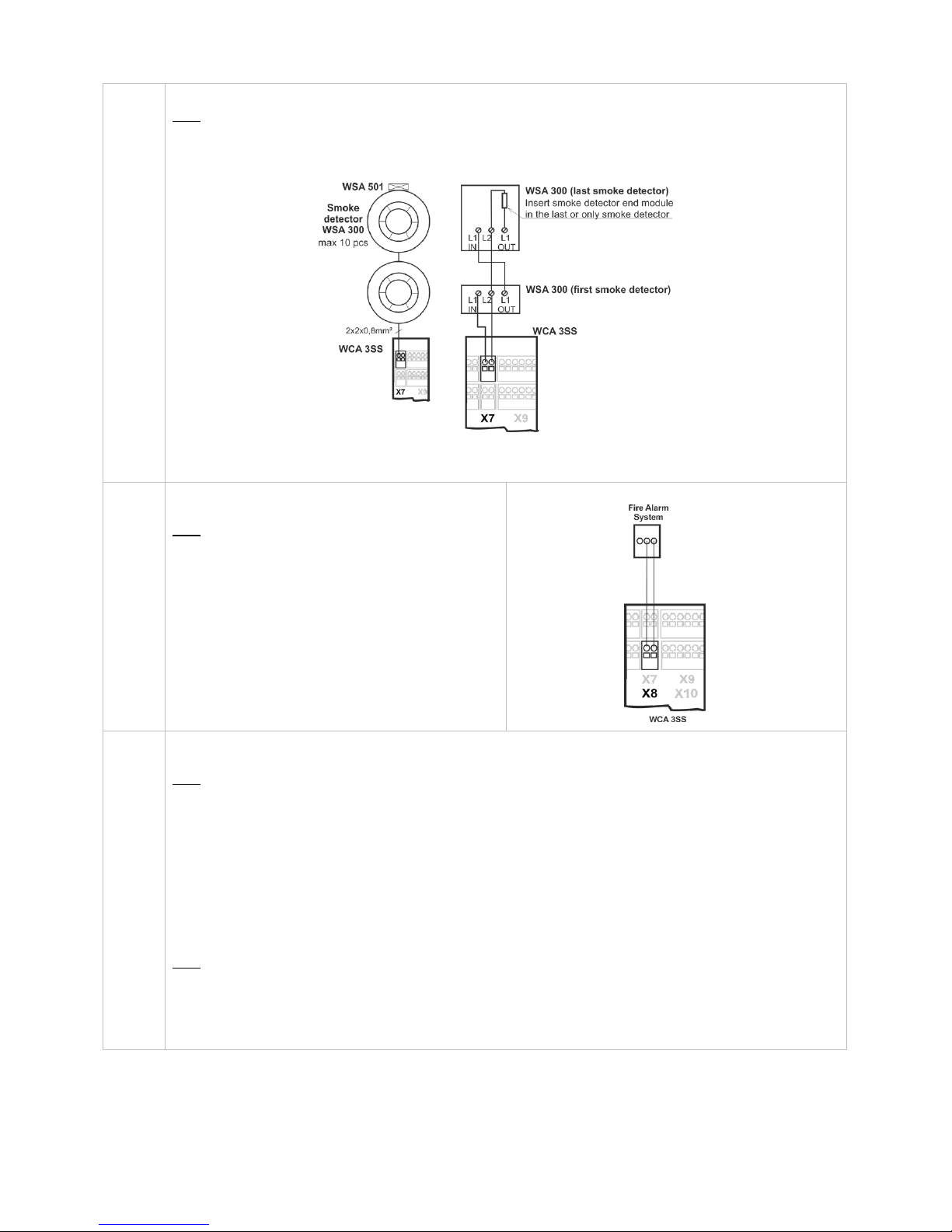
2 smoke zones and connected components; 2 break glass units type WSK 501 / 502 and 1 break glass unit
type WSK 503 / 504, 3 smoke detectors WSA 300, 2 resistances WSA 501 and 3 comfort keypads.
When there is no smoke detector connected to the WSK 501 / 502 a 10Ω resistor must be connected to the break
glass unit in to X7 and X8.
When a smoke detector is connected to the break glass unit, the 10Ω resistor must be connected to the last
smoke detector.
See chapter 9 "Cable plan for connection to WSC 3xx" for cable types and lengths.
Connection of different types of smoke detectors to CompactSmoke™
Smoke detector type
WSA 300
Hekatron
MSD 523
(max 5 pcs)
Hekatron
SSD 521/a
(WSA 200 6101)
Apollo, Orbis
ORB-OH-13001-AP0
ORB-OP-12001-AP0
Connect to WCA 3SS
X1,1
L1 In 2 2
In +
X1,2
L2 1 1
Com -
Connect to WSK
p 7
L2 1 1
Com -
p 8
L1 In 2 2
In +
ALWAYS connect 10 KOhm in
between
L2
and
L1 Out
1
and
3
1
and
3
Com –
and
Out +
Page 18
18
X7
For connection of smoke detector type WSA 300.
Data
7.1 +
7.2 Imax = 3,4mA
For connection of a different type smoke detector, see above.
When no smoke detector is connected to X7, a 10kΩ resistor is connected to the input.
X8
24/48V input from e.g. Fire Alarm System (used
primarily in France).
Data
8.1 +
8.2 Active at voltages between 18 and 50V
Passive below 1V
Max.50V
This input is only active when DIP switch 1.7 is ON,
see section 11.
When this input is in use, break glass units cannot
be connected to the panel.
Connection example
X9
Solid state outputs, one solid state output for transmission of fault signal to Fire Alarm System and 2 outputs
indicating alarm in the smoke zones.
Data
9.1 Fault – Open contact = Fault, closed contact = OK
9.2 Fault – Open contact = Fault, closed contact = OK
9.3 Output A, smoke zone 1 alarm – Open contact = normal, closed contact = Alarm
9.4 Output A, smoke zone 1 alarm – Open contact = normal, closed contact = Alarm
9.5 Output B, smoke zone 2 alarm – Open contact = normal, closed contact = Alarm
9.6 Output B, smoke zone 2 alarm – Open contact = normal, closed contact = Alarm
Solid state output for transmission of fault signal to Fire Alarm System.
A fault must last a minium of 20 seconds befoe the relay indicate a fault.
Data
Max voltage: 30 Vp (peak)
Max output: 150 mA
Typical On-resistance: 4,7 Ω
Max On-resistance: 8 Ω
Max switching speed: 2 ms
Page 19
19
X10
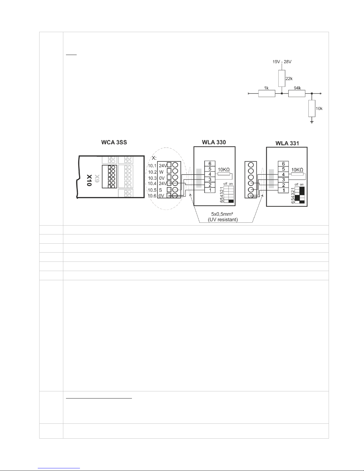
For connection of weather station.
Connection of wind / rain sensors type WLA 330 or rain sensor WLA 331.
Data
10.1 24V UPS (only available with Plus version)
10.2 Wind speed (only available with Plus version)
10.3 GND / 0V (only available with Plus version)
10.4 24V
10.5 Rain (10kΩ resistor is to be inserted when a rain sensor is not connected)
10.6 GND / 0V
With the default values are input:
”Active” if the contact resistance is smaller than 4kΩ
”Inactive” if the contact resistance is bigger than 8kΩ.
For values between 4 and 8kΩ the result will depend on the supply voltage.
Input has pull up approx. 1mA. (min 0.7mA, max 1.4mA)
Example: Wind/rain and rain sensors
WLA 330 and WLA 331– the settings of the sensors are set on the sensor.
J1
Connection for power supply
J3
Connection for battery (power back-up)
J8
USB host. Used for event log creation for e.g. error detection
J9
USB device. Used for remote control and update of firmware
P1
Power supply control
R / P
Reset / Programming (used for firmware updates)
DS 1 /
DS 2
2 DIP switch blocks with 8 DIP switches each
1.1 – 230V power failure
1.2 – Momentary action CLOSE (comfort ventilation)
1.3 – Momentary action OPEN (comfort ventilation)
1.4 – System fault triggers alarm
1.5 – VdS triggering by alarm
1.6 – Smoke detector – CLOSE (primarily used in Switzerland)
1.7 – 24V / 48V input active (primarily used in France)
1.8 – Actuators with higher run time than 61sec (both closing and opening speed)
2.1 – Run time limitation (comfort ventilation)
2.2 – Run time limitation (comfort ventilation)
2.3 – Run time limitation (comfort ventilation)
2.4 – Re-activation of run time limitation (OPEN)
2.5 – 20A on output X1
2.6 – Simple cable monitoring
2.7 – No grace timer
2.8 – Disable low stand-by power
See section 11 for further detail
LED
Shows the status of the panel
Red = alarm
Yellow = fault
Green fast flickering = all OK (CPU working), Green constant = CPU communication stopped (possible reset or
contact WindowMaster)
↓ ↑
Close / open all windows. When pressed together right after power has been connected the panel configures /
registers connected components.
Input circuit (simplified)
Page 20
20
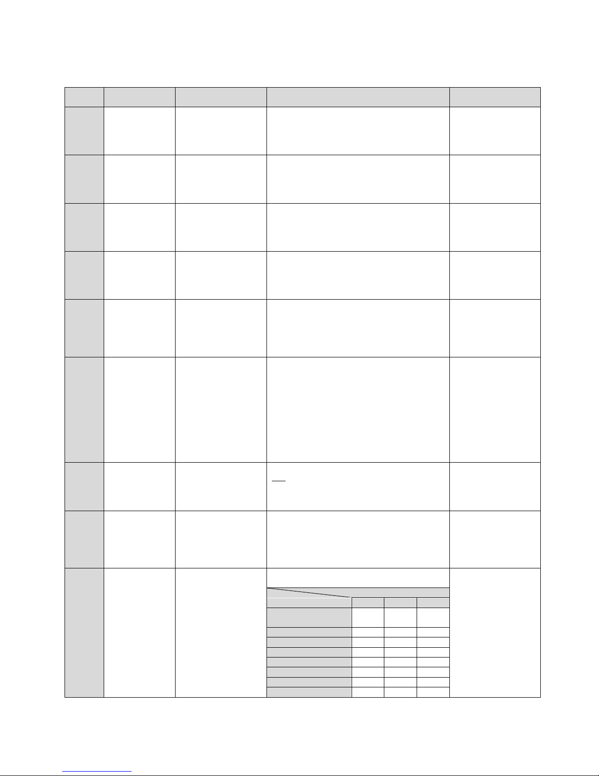
11 DIP switch configuration
For easy configuration of the smoke panel the Standard version includes 16 DIP switches. The factory settings for all the DIP
switches is OFF.
DIP
switch
Description on
the panel
Description
DIP switch position
Possible
consequence
1.1
No 230V Close
230V power failure
ON: The windows close in case of power
failure.
OFF: No change in position in case of power
failure.
This function
becomes suspended
when DIP switch 1.2
is ON.
1.2
Moment. act.
(Totmann) Close
Momentary action
CLOSE
(comfort ventilation)
ON: The window actuators run for as long as
the comfort keypad is pressed.
OFF: The windows close completely when
pressing the comfort keypad once.
This function
becomes suspended
when DIP switch 1.1
is on.
1.3
Moment. act.
(Totmann) Open
Momentary action
OPEN
(comfort ventilation)
ON: The window actuators run for as long as
the comfort keypad is pressed.
OFF: The windows open completely when
pressing the comfort keypad once.
1.4
Error Alarm
System fault triggers
alarm
ON: In case of fault (yellow diode lights), the
system will go into Alarm and the windows will
open.
OFF: Only fault indication
1.5
Re-triggering
(VdS)
VdS triggering by
alarm
ON: when the alarm is triggered the actuators
will, in accordance with VdS 2581, for a
duration of 30min be triggered to shortly
reverse and open every second minute.
OFF: Normal alarm
1.6
Smoke detc. (B)
Close
Smoke detector –
CLOSE
(primarily used in
Switzerland)
ON: When the alarm is triggered by a smoke
detector, the windows will close in all smoke
zones. A following operation of a break glass
unit will leave the system in alarm but trigger
the actuators to open the windows. Break
glass units have higher priority than smoke
detectors.
OFF: regardless if the alarm is triggered by
smoke detectors or break glass units, the
window actuators will open the windows
1.7
24/48V
24V / 48V input active
(primarily used in
France)
ON: The 24V / 48V input becomes active. Only
one smoke zone is possible.
OFF: the 24V / 48V input is deactive. Up to 2
smoke zones are possible.
1.8
Actuator 180
sec.
Actuators with higher
run time than 61sec
(both closing and
opening time)
ON: The panel will leave actuator voltage on
for 180 sec. Used for non EN 12101-2
actuators.
OFF: Used with actuators with a run time of
less than 60 sec (normal)
2.1- 2.3
Run time limit 1
Run time limit 2
Run time limit 3
Run time limitation
(OPEN)
(comfort ventilation)
The opening run time of the window actuators
can be limited via the DIP switch 2.1 - 2.3.
When using 24V DC
actuators, a full close
cycle must be carried
out (2 x run time ca.
120 sec.). Activated
by pressing the
“Close all windows”
button and wait for
min 2min. This resets
the current position.
DIP switch
Run time
2.1
2.2
2.3
No run time
limitation (normal)
OFF
OFF
OFF
83% (~ 50sec)
ON
OFF
OFF
67% (~ 40sec)
OFF
ON
OFF
50% (~ 30sec)
ON
ON
OFF
42% (~ 25sec)
OFF
OFF
ON
33% (~ 20sec)
ON
OFF
ON
25% (~ 15sec)
OFF
ON
ON
17% (~ 10sec)
ON
ON
ON
Page 21
21
DIP
switch
Description on
the panel
Description
DIP switch position
Possible
consequence
2.4
Run time reactivate
Re-activation of run
time limitation
(OPEN)
ON: If DIP switch 2.1 - 2.3 is activated, the run
time limitation can be reactivated.
OFF: normal
If DIP switch 2.1 - 2.3
is not activated, there
is no function on DIP
switch 2.4.
2.5
20A on X1
20A actuator output
on X1
ON: actuator output X1 is 20A and actuator
output X2 is 10A.
OFF: both actuator outputs (X1 & X2) are 10A
2.6
Simple cable
monitoring
Type of motor line
cable monitoring.
ON: simple monitoring. Short circuit between
all wires or cable break is detected.
OFF: Full monitoring. Short circuit between
any of the wires and break of any of the wires
is detected.
2.7
No grace timer
Deactivate grace
timer (manual
operation after an
safety command)
ON: Deactivate grace timer
OFF: Use standard grace timer 30 sec.
(default)
The grace timer is a safety feature that gives
the user the possibility to interfere with
automatic (non smoke) safety commands for
30 sec. After the 30 sec. has ran out the
actuator will return to the automatic position.
Smoke commands (Alarm/Reset) always has
first priority.
2.8
Disable low
stand-by power
Disalbes low power
consumption
ON: Low power mode is disable. Main power
supply is kept on.
OFF: Low power mode is enabled. Main power
shuts off, but turns on every 90sec due to
cable monitoring.
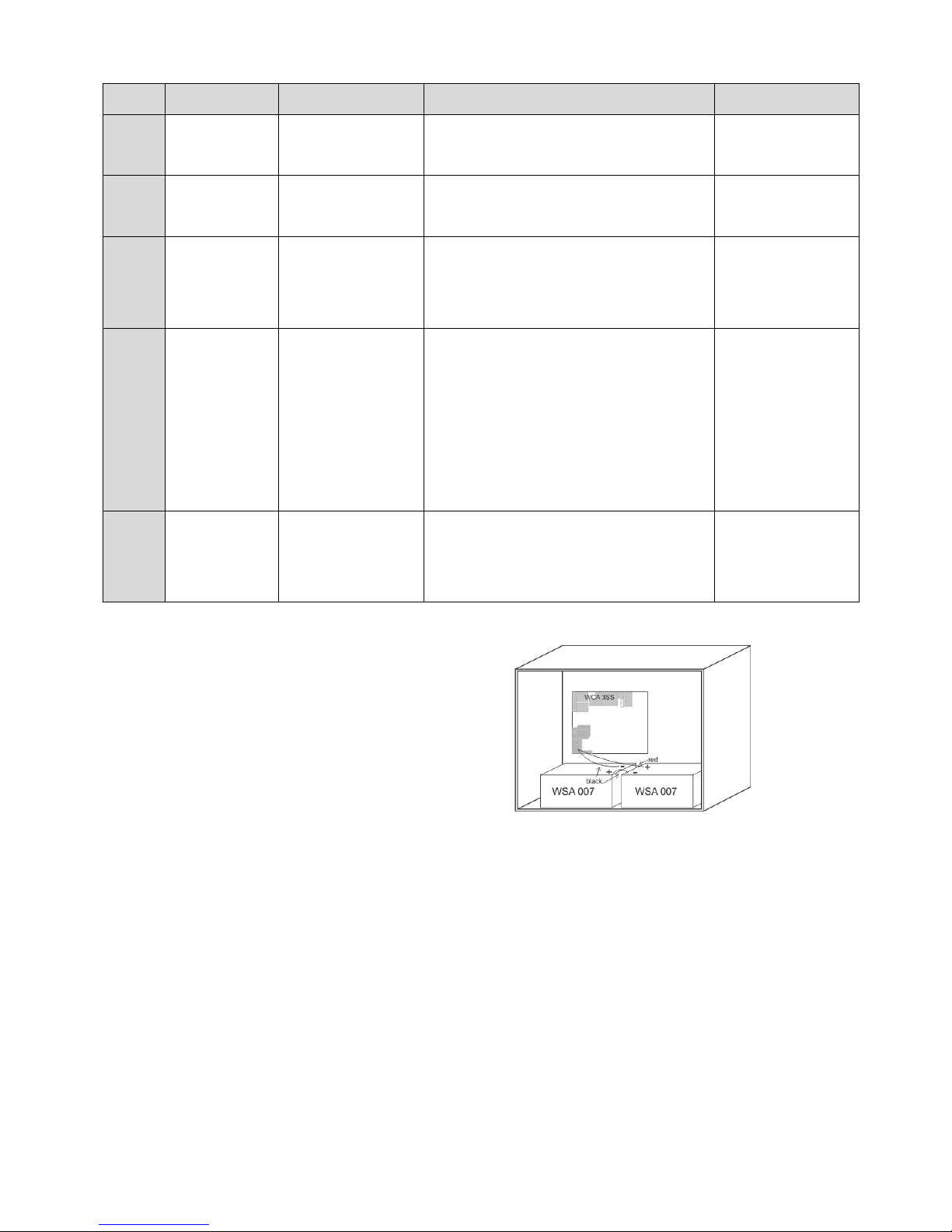
12 Back-up batteries
Connect 2 pcs. back-up batteries type
WSC 007 for WSC 310 and type WSA 012
for WSC 320.
See section 17 “Maintenance” for further
information.
Example of WSC 310 panel with back–up batteries.
13 Configuration of panel
The smoke panel is configured by pressing the two keys ”↑” and ”↓” on the main card, at the same time for 5-10 seconds.
The smoke panel must be configured
- After re-installation, changes, or change of actuators
- When / if MotorLink® actuators are connected
- If the cables have been moved
- When components are removed from the panel
- If there has been a fault on the WSK-Link™. Error blink sequence 6, see section 14.
Note, during reconfiguration both actuator outputs can be activated in both directions.
If the yellow diode on the main card blinks after a configuration, an error has occurred in the configuration, see section “Fault
detection via LED” for identification of errors.
13.1 Motor lines – motor groups – smoke zones
All the components connected to the Standard panel are automatically assigned to groups and zones:
- motor lines are assigned to motor groups
- motor groups are assigned to smoke zones
- break glass units and smoke detectors are assigned to smoke zones
Page 22
22
- keypads are assigned to one or more motor groups (via hard wiring)
13.1.1 Assigned components per smoke zone
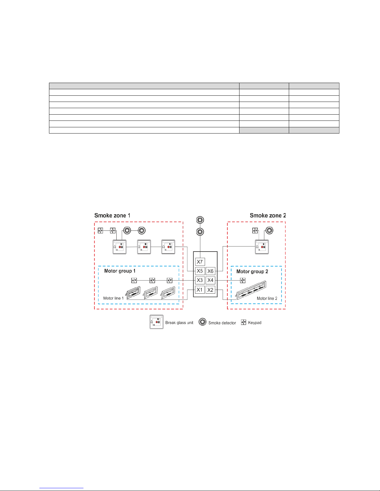
The number of used inputs for break glass units (X5 and X6) determines the number of smoke zones. If break glass units are
only connected to one of the inputs (X5), the systems will only have one smoke zone, whereas if break glass units are
connected to both inputs the system will have 2 smoke zones.
In case of 2 smoke zones, the connected components are assigned to the two smoke zones as shown in table below.
Connected components
Smoke zone 1
Smoke zone 2
Actuators connected to actuator output X1
X
Actuators connected to actuator output X2
X
Comfort keypads connected to input X3*
X
Comfort keypads connected to input X4*
X
Break glass units connected to input X5**
X
Break glass units connected to input X6**
X
Smoke detectors connected to input X7***
* will always only control motorline 1 (X3) respectively 2 (X4). One comfort keypad can be connected to both X3 and
X4 for control of both outputs.
** comfort keypads and smoke detectors belong to the same smoke zone as the break glass unit they are connected
to.
*** both smoke zones will be triggered by these smoke detectors.
If a rain/rain-wind sensor is connected to X10, the safety commands are sent to both smoke zones.
13.1.2 Examples with motor lines / motor groups / smoke zones
- 2 motor lines: one or more actuators connected to the lines
- 2 motor groups: the actuators in the motor group are operated simultaneously on the keypad
- 2 smoke zones: the actuators in the smoke zone are operated simultaneously on the break glass unit
13.1.3 Motor line
Actuators are to be connected on the motor lines. ±24V standard actuators and actuators with MotorLink® can be connected to
all motor lines, but a motor line can only be connected to one type of actuators – either ±24V standard or MotorLink® actuators.
The panel will automatically detect the type of actuator, which is connected to the panel.
13.1.4 Smoke zone
Depending on the settings on the DIP-switches the actuators will either open or close when the smoke panel is triggered, see
section 11.
Page 23
23
13.1.5 Local input
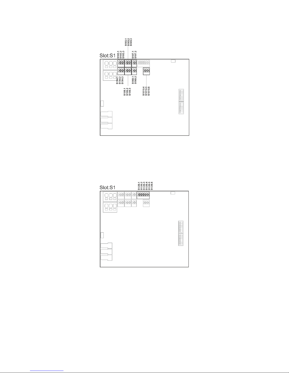
The seven inputs on the Standard version panels are pre-configured with the functions as shown below.
Inputs on the smoke ventilation panel
S1 X3 – X4 Comfort keypads configuration
S1 X5 – X6 Break glass units configuration
S1 X7 Smoke detector configuration
S1 X8 24V / 48V configuration
S1 X10 Weather station with wind direction configuration (only possible with the Plus version)
13.1.6 Local output
The output on the Standard version panels are pre-configured with the functions as shown below.
Smoke ventilation panel
S1 X9.1 – X9.2 Fault signal to fire alarm system configuration
S1 X9.3 – X9.4 Alarm triggering in smoke zone 1 configuration
S1 X9.5 – X9.6 Alarm triggering in smoke zone 2 configuration
14 Fault detection via LED
14.1 Fault detection on the smoke panel
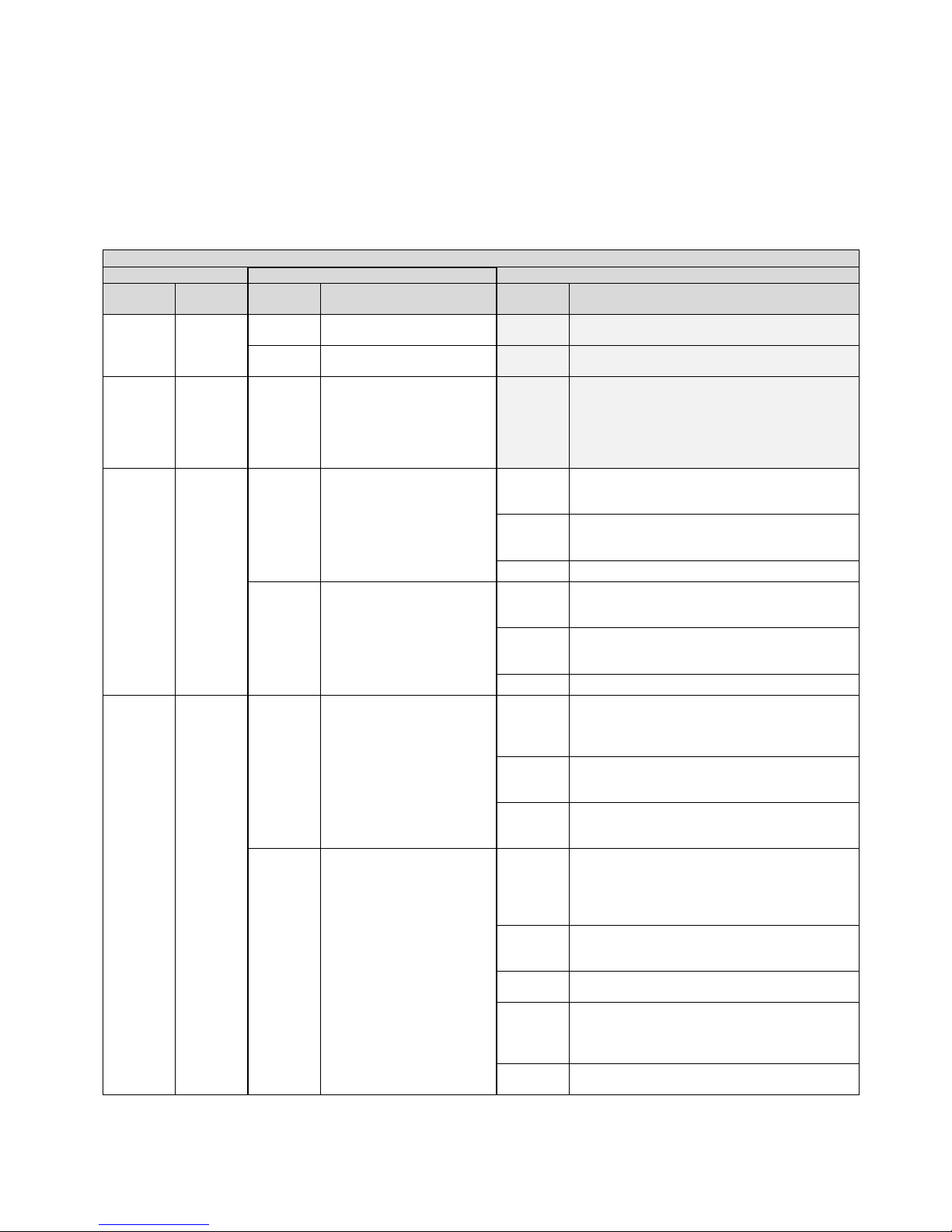
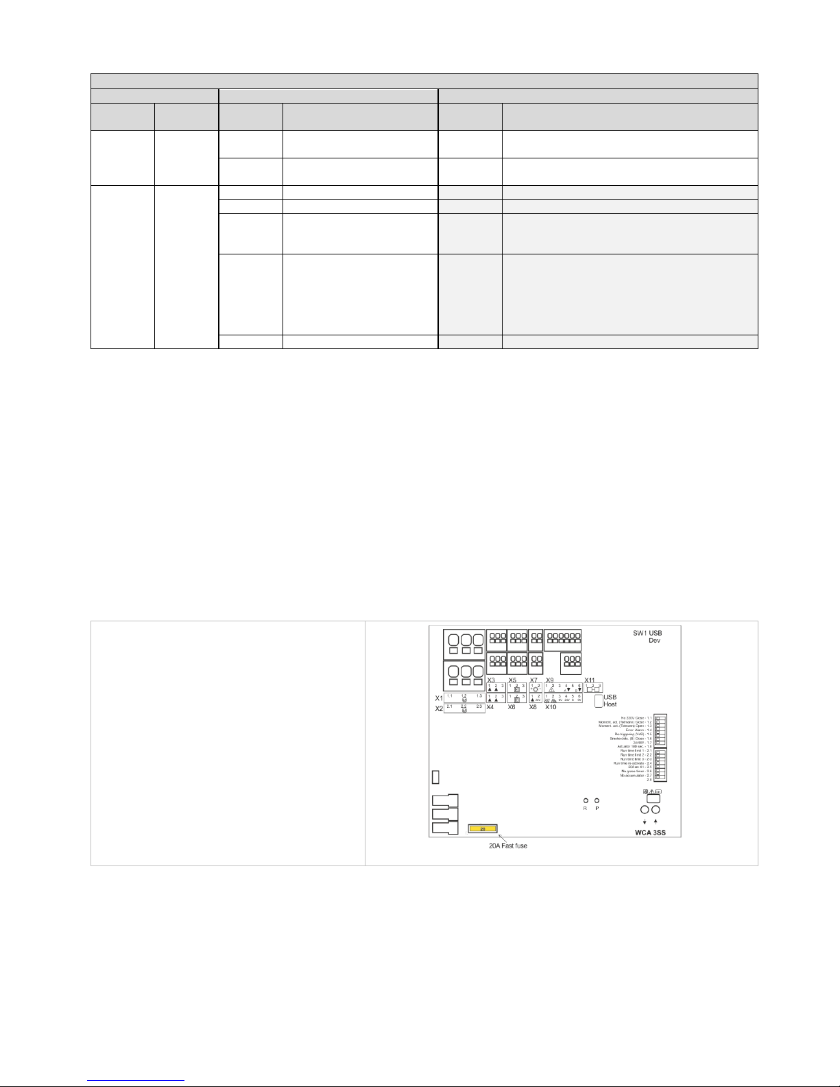
In case of error on the panel, the yellow diode on the main card will blink and via blink sequence indicate an error message.
Depending on the type of error message will consist of 2 or 3 blink sequences, separated by a seconds pause. The first blink in an
error message has a duration of one second, and thereby indicating when the error message (1st blink sequence) begins. The
remaining blinks of the error message has a duration of 0.5 seconds. The error message is repeated until the error has been
rectified. Between 2 error messages there is a pause of 2 sec.
Page 24
24
Example of an error message
”7 blinks – 1sec. pause – 2 blinks – 1 sec. pause – 1 blinks”.
1. There is an error on a local input
2. The error is on input X10.5, to which a rain sensor might be connected
3. The error is due to no connection to the sensor.
If there are more errors on the panel simultaneously, they are shown with priority, i.e. the error message for the most critical error is
shown first and repeated until rectified. Then the error message number 2 is shown and repeated as well until the error is rectified
etc.
Below table, list the most common errors.
Error message
1. Blink sequence
2. Blink sequence
3. Blink sequence
Number
of blink
Error on
Number
of blink
Error on or error type
Number
of blink
Error type
1
System
1
Internal error (Watchdog
reset)
2
Internal error (Program
CRC)
3
Smoke
zone
1
Max temp. in the panel has
been exceeded – reconfigure and check the
panel, see section 13 for
re-configuration of the
smoke panel
5
Actuator
1
X1 (actuator output)
1
Actuator configuration – check the actuators,
check the configuration, when using ±24V
standard actuators check the termination
2
Expected number of actuators, the found and
expected number of MotorLink® actuators does
not match – check actuator connections
4
Internal error
2
X2 (actuator output)
1
Actuator configuration – check the actuators,
check the configuration, when using ±24V
standard actuators check the termination
2
Expected number of actuators, the found and
expected number of MotorLink® actuators does
not match – check actuator connections
4
Internal error
6
WSKLink™
1
Bus
1
Closed ring – the standard version does not
allow break glass units connected in a closed
ring, check connection of break glass units and
disconnect the ring and re-configure
2
Problem on X5 (break glass unit) –
communication with the break glass unit
cannot be established
3
Problem on X6 (break glass unit) –
communication with the break glass unit
cannot be established
2
WSK
1
Problem (short circuit, cable problem or
termination) with break glass unit #2
connected to a break glass unit– check
connection of break glass unit and termination
smoke detector input
2
Slave panel – the standard version does not
allow connection of a slave panel. Remove the
slave panel and re-configure
3
Offline break glass unit, one or more break
glass are offline – check and re-configure
4
Break glass unit sensor (smoke detector
connected to break glass unit) – check
connection between break glass unit, sensor
and end-module (termination)
5
The break glass unit version is too old – break
glass units must be renewed
Page 25
25
Error message
1. Blink sequence
2. Blink sequence
3. Blink sequence
Number
of blink
Error on
Number
of blink
Error on or error type
Number
of blink
Error type
7
Local
input
1
X7 (smoke detector)
1
Termination – check connection of detectors
as well as termination
2
X10.5 (rain sensor)
1
Termination – check connection of sensor as
well as termination
10
Power
supply
1
Internal error
2
Mains – check connection
3
Back-up batteries – check
connection or replace the
batteries
4
Max temp. in the panel has
been exceeded – reconfigure and check the
panel, see section 13 for
re-configuration of the
smoke panel
5
Internal error
If other errors or an “Internal error” are indicated, please contact WindowMaster.
14.2 Fault indication on break glass unit
If the smoke panel loses the mains connection (230V), the green LED on the break glass unit (WSK 501 / 502 / 503 / 504) will flash.
The green LED will flash until the system goes into alarm (check power supply (error message 10.2)).
With the standard settings it can take up to 10min before the loss of connection is registred.
15 Hardware error
If there are any hardware error on the panel it will be indicated by the diodes (yellow diode is lit).
15.1 Error on the Power supply
Mains power failure will trigger an error. Within the first minute after te failure has been detected, the green LED in the break glass
unit will start to blink. After 30 minutes (parameter setting), the error is indicated via LED blink sequence, see “Fault detection on the
smoke panel”, and the windows will close.
Furthermore, non connected, wrong connected or ”dead” batteries can trigger an error on the ”Power supply”.
15.1.1 Blown fuse – 20A fast
Additionally, an error on the ”Battery status” can also be triggered if the fuse (20A fast) is blown.
The fuse is located in the bottom left corner of the
main card.
Location of 20A fast fuse
16 Commissioning and test run
In case of hardware error please see chapter 14 “‘Hardware error”. To configure the smoke panel press „↑“ and „↓“ (on the main
card) at the same time for 5-10 seconds, see section 13.
The break glass unit WSK 50x will only give an acoustic fault signal if the door on the break glass unit is closed or if the door
contact on the break glass unit is pressed.
We recommend that the software of the panel is updated during the annual maintenance check!
We recommend that the commissioning of the smoke panel should be done by a competent smoke ventilation controls installer.
Page 26

26
16.1 The control ventilation panel is completely installed, without the operating
voltage applied
a) Check all mechanical and electrical components for damage.
b) Check all screw and plug connections for tightness and/or firm seating
c) Check that all external components are installed:
1) ±24V actuators: Is the motor end module inserted in the last or only actuator?
2) Automatic smoke detectors: Is the passive end module inserted in the last or only smoke detector?
16.2 With mains voltage, without accumulator
Adhere to the relevant regulations!
Connect the mains cables and reapply the mains voltage.
16.3 With mains voltage, with accumulator
a) Remove the protection film from one face of the supplied foam rubber. Glue each foam rubber to the bottom side of the
accumulators. Connect the accumulators to the black accumulator bridge according to the wiring diagram, then connect the
red and the black connection cable to the red and the black flat plug. Remove the bottom protection film of the foam rubber
and insert the batteries in the smoke ventilation panel according to section 11, and firmly press down to the housing bottom!
b) Plug the red connection cable to the + and the black connection to the flat plug of the control panel.
Note: Check correct polarity!
16.4 Ventilation keypad
Closely observe the actuators during opening and closing. They must not be impaired in any position by the building structure.
Observe that the actuator cables are not being subject to pulling or pinching.
Check each ventilation keypad individually.
16.5 Break glass unit WSK 50x
a) Open the door and press the red Open button. The actuators move open through to the end position. The red alarm LED
(also in the control panel) is ON; at the same time a permanent acoustic signal sounds (door contact on the break glass unit
is pressed!).
b) Press the Reset/Closed button in the break glass unit. The actuators close through to the end position. The comfort
ventilation function is released again. The red alarm LED (also in the smoke ventilation panel) and the acoustic smoke alarm
are turned off.
16.6 Smoke detectors
a) Spray test aerosol on the smoke detectors (aerosol item no. 9549).
b) The actuators move open through to the end position. The red LED in the smoke detector, the red alarm LED (also in the
smoke ventilation panel) and the permanent acoustic signal in the break glass unit are ON.
c) Press the Reset/Closed button in the break glass unit - the actuators close through to the end position.
The comfort ventilation function is released again. The red alarm LED in the break glass unit and in the smoke control panel
as well as the acoustic smoke alarm are turned off.
16.7 Emergency power supply test
a) Remove the mains fuse from the smoke ventilation panel. Wait 10 minutes (or run the actuators shortly). See also national
guidelines.
b) When a mains error have occurred the green LED in the break glass units will flash for 30 minutes. The green LED on the
WCA 3SS card in the smoke ventilation panel is still on and the yellow LED is turned off.
c) After 30 minutes the green LEDs will turn off and all the yellow LEDs in the smoke ventilation panel and the break glass units
will lit continuously.
d) Check that the comfort ventilation keypads are deactivated.
e) Check that the break glass units are working (section 15.5)
f) Refit the mains fuse.
g) The green mains and operating LED's are on, the yellow LED is off, the malfunction message at the break glass unit is off.
16.8 Wind/rain detector
a) Open the actuators with the comfort ventilation keypads.
b) Wet the rain sensor, the actuators will fully close.
c) While the actuators are running, press the Open button at the keypad. The actuators must neither open nor stop!
Exception: If a manual override time (Man. operation after auto comm.).
d) Any smoke and heat extraction signal will always take priority over the wind/rain signal.
e) While the rain sensor is active (wet) the smoke ventilation panel is activated (alarm) and the actuators move open through to
the end position (alternatively to the SHE position)
If the start-up was successful, close the doors of the break glass units and of the smoke ventilation panel.
If the start-up was unsuccessful (error with one of the test run processes), please see chapter 10 “Description of cards”.
If necessary, check the wiring in accordance with the cable plan – see chapter 9 “Cable plan for connection to WSC 3xx”.
Page 27

27
17 Maintenance
The panels of the smoke and heat exhaust ventilation system have to be checked, serviced and, if necessary, repaired at least
once per year by the manufacturer or an authorized partner
Remove all soiling from the units of the smoke and heat exhaust system. Check fastening and clamping screws for firm seating.
Carry out a test run of the entire system (see chapter 15 ‘Commissioning and test run).
Only have defective units repaired in our factory. Only install original spare parts.
Check the operational condition at regular intervals. We recommend a WindowMaster service contract is taken out to ensure the
right function of the smoke and heat exhaust system.
All back up batteries coming with the smoke control panel as standard; have to be subjected to regular checks.
The smoke ventilation panel will signal fault on the batteries if the battery voltage is below 17V.
Within the framework of the service, they have to be replaced after the specified maximum 4 year operating period.
Dispose of used batteries according to the National regulation.
CAUTION: RISK OF EXPLOSION IF BATTERIES ARE REPLACED BY AN INCORRECT TYPE.
We recommend that the software of the panel is updated during the annual maintenance check!
The expected minimum lifetime for the CompactSmoke™ is 10 years excluding the batteries.
17.1 Maintenance agreements
Be aware that regular inspection of smoke ventilation systems is a legal requirement. The legislation requires that the smoke
ventilation system's owner inspects and tests the system once every year.
WindowMaster offer maintenance agreements for the smoke ventilation system and every year we inspect the complete system
to ensure it complies with the applicable legislation. Maintenance of the smoke ventilation system includes checking windows,
window actuators and emergency power and checking that triggering and control functions are fully functional.
Contact our service department for further information: telephone +44 1536 510990 or [email protected]
17.2 Replacement 3SS card
1. Disconnect the 230 V and the batteries.
2. Insert the 3SS replacement card.
3. Turn on the 230 V and connect the batteries.
4. The system will be ready again after approx. 2 seconds.
18 Declaration of Conformity and Declaration of Perfomance
The smoke ventilation panels are manufactured and tested accordingly to the European requirements.
The total system is not to be put into service until a declaration of conformity for the total system has been made.
The “Declaration of Conformity” and the EN certificate are supplied with panel as separate documents.
 Loading...