

Window Master WSC 310, WSC 320 Installation Instructions Manual
UK
+44 (0) 1536 614 070
Info.uk@windowmaster.com
Other markets
+45 4567 0300
Info.dk@windowmaster.com
www.windowmaster.com
WSC 3xx iinstall 1711-Firmware v126 - UK ©WindowMaster 2015, 2017 ®WindowMaster is a registred trademark used under the license by WindowMaster International A/S
WindowMaster International A/S, Skelstedet 13, DK-2950 Vedbæk
WSC 310 & WSC 320
Plus versions
Installation instruction
CompactSmoke™
(Version 1711 – from firmware version 1.26 (main card) &
from version 1.06 (motor line card))
Save this installation instruction to the end user

2
1 Safety information ........................................................................................................................................................ 4
1.1 Safety ................................................................................................................................................................ 4
1.2 230V AC ............................................................................................................................................................ 4
1.3 Back-up batteries .............................................................................................................................................. 4
1.4 Application ......................................................................................................................................................... 4
1.5 Cable routing and electrical connection ............................................................................................................. 4
2 Structure of the smoke panel ...................................................................................................................................... 5
3 Variants of panels ........................................................................................................................................................ 6
3.1 CompactSmoke™ Plus versions ....................................................................................................................... 7
3.2 Max numbers of actuators per motor line and panel
............................................................................................. 7
4 Accessories and spare parts ...................................................................................................................................... 8
5 Technical data .............................................................................................................................................................. 9
6 Mounting ..................................................................................................................................................................... 11
7 Installation .................................................................................................................................................................. 11
7.1 Cable routing ....................................................................................................................................................11
7.2 Cables into housing ..........................................................................................................................................11
7.3 Connection of safety earth wire and 230V AC ..................................................................................................11
7.4 Installation of the break glass unit, ventilation keypad and smoke detector .....................................................11
7.5 Assembly instructions .......................................................................................................................................12
8 Cable dimensioning ................................................................................................................................................... 12
8.1 Maintaining the cable functions ........................................................................................................................12
8.2 Max. cable Length ............................................................................................................................................12
8.2.1 Formula for the calculation of the maximum actuator cable length ............................................................. 12
8.2.2 Max cable length – ±24V standard actuators .............................................................................................. 13
8.2.3 Max cable length – actuators with MotorLink® ............................................................................................. 13
9 Cable plan for connection to WSC 310 / 320 Plus version ..................................................................................... 15
10 Description of cards and mains connection ............................................................................................................ 16
10.1 WSC 310 mains connection and power supply unit (WCA 3P1) ......................................................................16
10.2 WSC 320 mains connection and power supply unit (WCA 3P2) ......................................................................16
10.3 Connections between cards .............................................................................................................................17
10.4 Main control card WCA 3SP – Plus Version .....................................................................................................17
10.5 Motor line card – WCA 3M8 .............................................................................................................................28
10.6 Keypad card – WCA 3KI ..................................................................................................................................29
10.7 Fieldbus cards ..................................................................................................................................................29
11 Cable monitoring of actuators .................................................................................................................................. 30
11.1 Usage of non-WindowMaster actuators ...........................................................................................................30
12 Back-up batteries ....................................................................................................................................................... 30
13 Touch screen .............................................................................................................................................................. 31
13.1 Icons .................................................................................................................................................................31
13.2 Rotation of the touch screen ............................................................................................................................32
14 Configuration – main menu ....................................................................................................................................... 32
14.1 Motor lines – motor groups – smoke zones ......................................................................................................32
14.1.1 Examples with motor lines / motor groups / smoke zones ........................................................................... 32
14.2 Motor line .........................................................................................................................................................33
14.2.1 Motor line - numbering ................................................................................................................................ 33
14.2.2 Motor line - configuration ............................................................................................................................. 33
14.2.3 Colour code - motor line .............................................................................................................................. 35
14.3 Motor group ......................................................................................................................................................35
14.3.1 Motor group - configuration ......................................................................................................................... 35
14.3.2 Colour code – motor group .......................................................................................................................... 35
14.4 Break glass unit ................................................................................................................................................35
14.4.1 Break glass unit – configuration .................................................................................................................. 35
14.4.2 Colour code – break glass unit .................................................................................................................... 37
14.5 Smoke zone .....................................................................................................................................................37
14.6 Local input ........................................................................................................................................................38
14.6.1 Numbering of local inputs ............................................................................................................................ 38
14.6.2 Local input - configuration ........................................................................................................................... 39
14.6.3 Usage of wind/rain sensors - WLA 33x ...................................................................................................... 40
14.7 Local output ......................................................................................................................................................41
14.7.1 Numbering of local output ........................................................................................................................... 42
14.7.2 Local output - configuration ......................................................................................................................... 42
14.8 Weather station type ........................................................................................................................................43
14.9 Sequence control .............................................................................................................................................44
14.10 Magnetic clamp (magnetic door retainer) .........................................................................................................44
14.11 Master / Slave connection of smoke zones ......................................................................................................45
14.12 Network ............................................................................................................................................................47
14.14 Log in ...............................................................................................................................................................48
14.15 Configuration files on USB ...............................................................................................................................49
14.16 System .............................................................................................................................................................49
14.16.1 Service timer ............................................................................................................................................... 50

3
14.17 Fieldbus (KNX and BACnet) .............................................................................................................................51
14.17.1 KNX configuration ....................................................................................................................................... 51
14.17.2 BACnet configuration .................................................................................................................................. 52
15 Status – main menu ................................................................................................................................................... 52
16 Manual operation – main menu ................................................................................................................................. 52
17 Configuration missing – main menu ........................................................................................................................ 53
18 Hardware error – main menu ..................................................................................................................................... 53
18.1 Error on the Power supply ................................................................................................................................53
18.1.1 Blown battery fuse – 20A fast ...................................................................................................................... 54
19 View all details – main menu ..................................................................................................................................... 54
20 Remote control of CompactSmoke™ ....................................................................................................................... 54
21 Commissioning and test run ..................................................................................................................................... 55
21.1 The control ventilation panel is completely installed, without the operating voltage applied .............................55
21.2 With mains voltage, without accumulator .........................................................................................................55
21.3 With mains voltage, with accumulator ..............................................................................................................56
21.4 Ventilation keypad ............................................................................................................................................56
21.5 Break glass unit WSK 50x ................................................................................................................................56
21.6 Smoke detectors ..............................................................................................................................................56
21.7 Emergency power supply test ..........................................................................................................................56
21.8 Wind/rain detector ............................................................................................................................................56
22 Maintenance ............................................................................................................................................................... 56
22.1 Maintenance agreements .................................................................................................................................57
22.2 Replacement cards ..........................................................................................................................................57
22.2.1 Replacement of 3M8 and 3KI cards ............................................................................................................ 57
22.2.2 Replacement of 3SP card ........................................................................................................................... 57
23 Declaration of Conformity and Declaration of Perfomance.................................................................................... 57

4
1 Safety information
1.1 Safety
Only allow correspondingly trained, qualified and skilled personnel to carry out installation work.
Reliable operation and the avoidance of damage and hazards are only guaranteed if installation and settings are carried out
carefully in accordance with these instructions.
There may be personal danger by electrically operated windows:
- the forces occurring in the automatic mode can be such that parts of the body could get crushed
- when opened, actuators (spindles) could protrude into the room
For this reason, measures have to be taken prior to starting up the actuators, which exclude the danger of injury.
For safety reasons we recommend to install opening restrictors on bottom-hung windows.
In the event that windows are subjected to rain and/or high wind loads, we recommend connecting a wind/rain sensor to the
smoke ventilation panel for the automatically closing of the windows.
The smoke ventilation panel is to be located in a safe place, protected from the effects of fire and smoke.
The smoke ventilation panel is to be surface mounted.
The smoke ventilation panel has two energy suppliers: 230V AC and back-up batteries.
The manufacturer does not assume any liability for possible damage resulting from inappropriate use.
1.2 230V AC
230V AC can cause death, severe injury or considerable damage to assets.
The connection of the smoke ventilation panel is reserved for qualified personnel.
Disconnect all poles of the panel from the supply voltage prior to opening, installation or assembling.
Installation and use according to the national regulations.
1.3 Back-up batteries
Back-up batteries 2 batteries per panel can cause severe injury or considerable damage to assets.
The connection of the smoke ventilation panel is reserved for qualified personnel.
Disconnect all poles of the panel from the back-up batteries prior to installation or assembling.
Ensure that the mains cable can be switched via an external or customer-supplied two-pole switch element or a switch element
controlling all poles – see section 7.1 “Cable routing”.
Installation and use according to the National regulations.
Dispose of used batteries according to the National regulation.
CAUTION
RISK OF EXPLOSION IF BATTERIES ARE REPLACED BY AN INCORRECT TYPE.
1.4 Application
The smoke ventilation panel is exclusively designed for the automatic opening and closing of smoke extraction systems,
windows, flaps or doors.
Always check that your system meets the valid national regulations.
Pay particular attention to the opening cross section, the opening time and opening speed.
The cable cross sections depend on the cable length and current consumption (amperage).
1.5 Cable routing and electrical connection
Fuse the 230VAC power supply cable separately on site.
Cable routing and connection - adhere to national regulations.
Establish the cable types, if necessary, with the local approval bodies or the fire protection authority.
Do not conceal flexible cables.
Junction box must be accessible for maintenance purposes.
Disconnect all poles of the mains voltage and the back-up batteries prior to starting maintenance work or making changes to the
system.
Secure the system to prevent unintentional switching on again.
Route all low voltage cables (24VDC) separate from the power current cables.
Design cable types, lengths and cross sections in accordance with the technical information.
Cable specifications is a guide only, the overall responsibility resides with the electrical contractor on site.
Installation must be in accordance with the national electrical regulations.
5
2 Structure of the smoke panel
Sizes & Versions
The WSC 310 and WSC 320 smoke ventilation panels are available in two different versions namely a Standard and a Plus
version. This installation instruction only deals with the Plus versions. Please see separate installation instruction for the
Standard versions of WSC 310 and WSC 320.
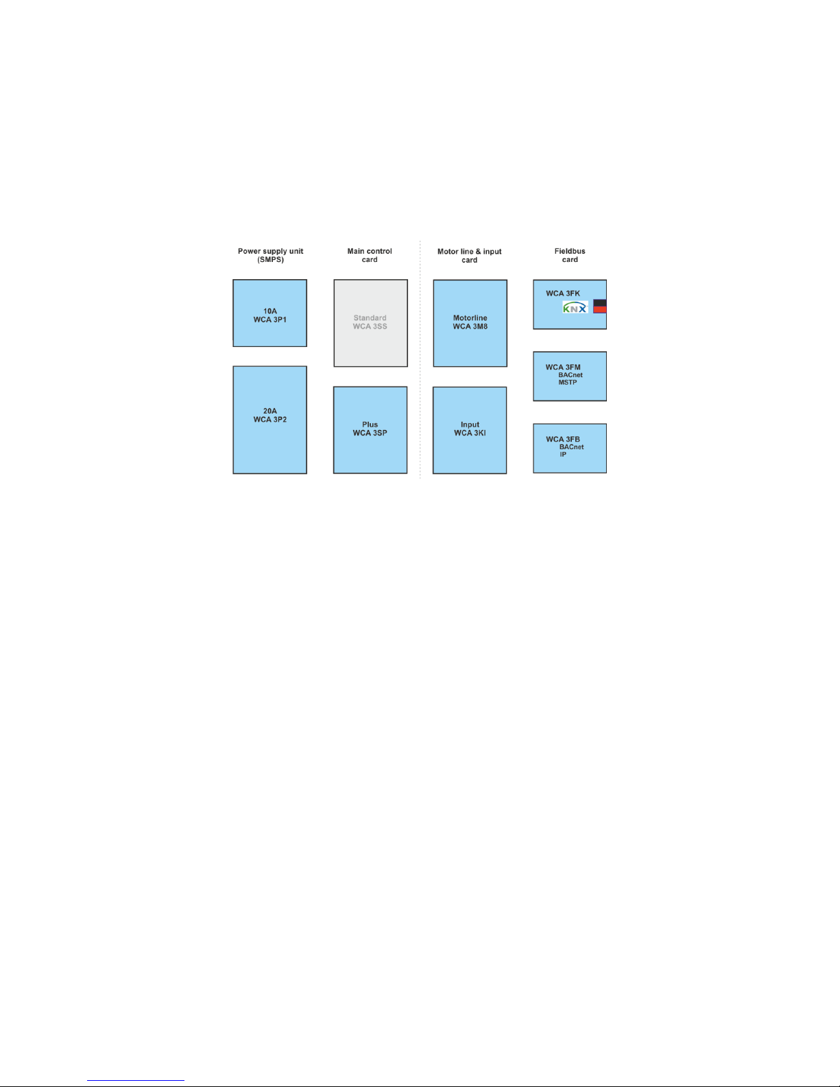
Cards
Each panel contains a power supply unit (SMPS), either a WCA 3P1 or a WCA 3P2 for the 10A or 20A version respectively.
Aside from the power supply unit the Plus version also includes a main control card type WCA 3SP, which includes a touch
screen for easy configuration of the panel. Motor line and input cards, as well as fiedbus cards, can be added to the panel
depending on requirements.
Selection of cards
The Main control card type WCA 3SP allows connections of 2 motor lines and 2 keypads. If more than 2 motor lines or 2
keypads are required, the necessary cards can be added.
Cards:
- WCA 3M8 motor line card, allows additional 8 motor lines.
- WCA 3KI input card, allows additional 10 keypads (requires WCA 3M8).
A fieldbus card must be added, if communication via KNX or BACnet is required.
Fieldbus cards:
- WCA 3FK fieldbus card, fieldbus interface for KNX
- WCA 3FM fieldbus card, fieldbus interface for BACnet / MSTP
- WCA 3FB fieldbus card, fieldbus key for BACnet IP
Installation of cards may only be done when there is no power on the panel (no battery or power on). Motor line and input cards
are ordered together with the panel and mounted to the panel from the factory side, whereas the fieldbus cards are delivered as
individual products and are to be mounted by the customer – see separate installation manual for mounting of fieldbus card.
The item no. of the panel specifies the type and mounting of the cards - see "Variants of panels" for more information
Motor groups and motor lines
A motor group consists of one or more motor lines and all the motor lines are operated simultaneously.
The motor lines on both the main control card (WCA 3SP) and the motor line card (WCA 3M8) can all be configured for either a
±24V standard actuators or MotorLink® actuators. A motor group can contain motor lines with both ±24V standard actuators and
MotorLink® actuators, whereas a motorline only can have ±24V standard or MotorLink® actuators connected.
Adding panels
The smoke ventilation installation can be expanded by adding more panels and creating a master/slave connection among
them. The master/slave connection is done directly on the WSA 3SP card. On the master panel the break glass inputs are used
and on the slave panel the X11 input is used. The total cable length between 2 panels must not exceed 200m.
Break glass unit
Break glass unit type WSK 50x are to be used together with WSC 310/320. The units are configured and assigned to smoke
zones via the touch screen on the main control card WCA 3SP.
6
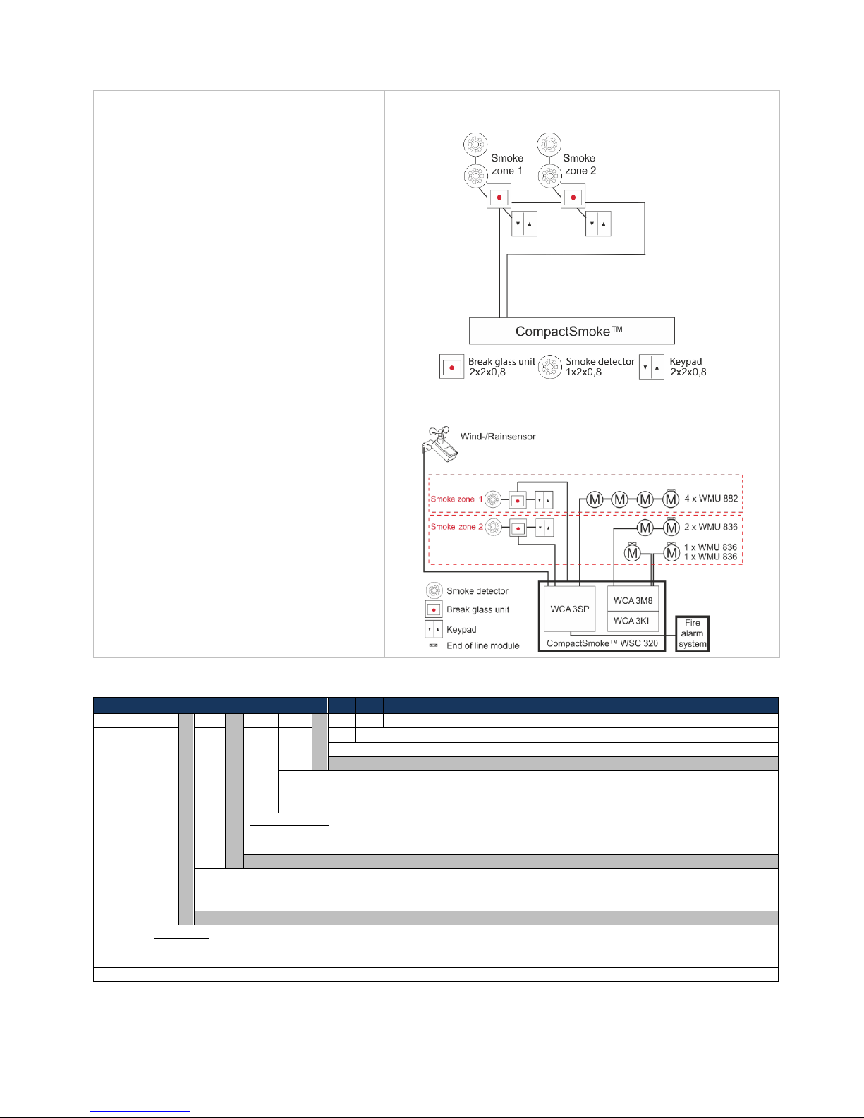
Inputs
Cabling
The WSC 3xx CompactSmoke™ uses bus
technology and the overall cabling for break
glass units, smoke detectors and keypads is
significantly reduced compared to other types of
smoke panels.
The main control card has 1 input for a smoke
detector, 2 inputs for break glass units (where
up to 10 break glass units can be connected)
and 2 inputs for ventilation keypads (no max
number of keypads).
Smoke detectors are either connected to the
smoke detector input or to a break glass unit
(type WSK 501 / 502).
The number of smoke zones and motor groups
can be configured as required.
- max 2 smoke zones and 2 motor groups for a
panel without motor line card.
- max 10 smoke zones and 10 motor groups for
a panel with motor line card
System example with WSC 320
Smoke ventilation panel (20A) motor line and
keypad card configured in 2 smoke zones.
The keypads and smoke detector units are
cabled directly to the break glass units in the
smoke zones, which means that the need for
cabling in the building is significantly reduced.
A wind/rain sensor is connected to close the
windows during comfort ventilation in case of
high wind and/or rain.
The smoke ventilation panel is connected to the
Fire Alarm System via the WCA 3SP card.
3 Variants of panels
Item composing
WSC 3
xx x xx
xx x 1
1 = Product version number
E = EN 12101-10
Input card*
02 = No input card
12 = Input card (10 additional keypad inputs)
Motor line card
02 = No motor line card
10 = Motor line card (8 additional lines)
Panel version
S = Standard
P = Plus
Panel size
10 = 10A
20 = 20A
Compact smoke series 3
* Input card for keypads requires card for motor lines

7
3.1 CompactSmoke™ Plus versions
Number of motor lines and other functions
Cards
Item number
Examples with WSC 310
Plus version
2 motor lines
2 keypads / inputs
No cards
WSC 310 P 0202 E1
Example with WSC 320
Plus version
2 motor lines
2 keypads / inputs
No cards
WSC 320 P 0202 E1
Plus version
10 motor lines
12 keypads / inputs
1 x WCA 3M8
1 x WCA 3KI
WSC 320 P 1012 E1
3.2 Max numbers of actuators per motor line and panel
The table shows the maximum number of actuators, which can be connected per motor line and panel depending on the type of the
actuator, panel and connected card. The total power consumption of all the connected actuators must not exceed 10A for WSC 310
and 20A for WSC 320.
Actuator type
Per Motor line
Per 10A panel
Per 20A panel
± 24V
actuators
MotorLink®
actuators
± 24V
actuators
MotorLink®
actuators
± 24V
actuators
MotorLink® actuators
2 motor lines
2 motor lines
10 motor lines
WMS 306-1
10 4 10 8 20 8 20
WMS 306-2
10 2 10 4 20 4 20
WMS 306-3
9 3 9 6 18 6 18
WMS 306-4
8 4 8 8 20 8 20
WMS 309-1
10 4 10 8 20 8 20
WMS 309-2
10 2 10 4 20 4 20
WMS 309-3
9 3 9 6 18 6 18
WMS 309-4
8 4 8 8 20 8 20
WMS 409 xxxx 01
5 0 5 0 10 0 0
WMS 409-1
5 4 5 4 10 8 10
WMS 409-2
4 2 4 4 8 4 10
WMS 409-3
3 3 3 3 9 6 9
WMS 409-4
4 4 4 4 8 8 8
WMS 515 2 0 2 0 4 0
0
WMU 836-1
10 4 10 8 20 8 20
WMU 836-2
10 2 10 4 20 4 20
WMU 836-3
9 3 9 6 18 6 18
WMU 836-4
8 4 8 8 20 8 20
WMU 861-1
6 4 6 6 12 8 12
WMU 861-2
6 2 6 4 12 4 12
WMU 861-3
6 3 6 6 12 6 12
WMU 861-4
4 4 4 4 12 8 12
WMU 842 / 862 / 882-1
4 4 4 4 8 8 8
WMU 842 / 862 / 882-2
4 2 4 4 8 4 8
WMU 842 / 862 / 882-3
3 3 3 3 6 6 6
WMU 842 / 862 / 882-4
4 4 4 4 8 8 9
WMU 863 / 883-1
3 3 3 3 6 6 6
WMU 863 / 883-2
2 2 2 2 6 4 4
WMU 863 / 883-3
3 3 3 3 6 6 6
WMU 863 / 883-4
0 0 0 0 4 4 4

8
Per Motor line
Per 10A panel
Per 20A panel
± 24V
actuators
MotorLink®
actuators
± 24V
actuators
MotorLink®
actuators
± 24V
actuators
MotorLink® actuators
2 motor lines
2 motor lines
10 motor lines
WMU 864 / 884-1
2 2 2 2 4 4 4
WMU 864 / 884-2
2 2 2 2 4 4 4
WMU 864 / 884-3
0 0 0 0 3 3 3
WMU 864 / 884-4
0 0 0 0 4 4 4
WMU 885 / 895-1
2 2 2 2 4 4 4
WMU 885 / 895-2
2 2 2 2 4 4 4
WMU 885 / 895-3
0 0 0 0 3 3 3
WMU 885 / 895-4
0 0 0 0 4 4 4
WMX 503 / 504 / 523 / 526-1
20 4 20 8 40 8 40
WMX 503 / 504 / 523 / 526-2
20 2 20 4 40 4 20
WMX 503 / 504 / 523 / 526-3
18 3 18 6 39 6 30
WMX 503 / 504 / 523 / 526-4
20 4 20 8 40 8 40
WMX 803 / 804 / 823 / 826-1
10 4 10 8 20 8 20
WMX 803 / 804 / 823 / 826-2
10 2 10 4 20 4 20
WMX 803 / 804 / 823 / 826-3
9 3 9 6 18 6 18
WMX 803 / 804 / 823 / 826-4
8 4 8 8 20 8 20
WML 820/825
10 0 10 0 20 0 0
WML 860-1
10 4 10 8 20 8 20
WML 860-2
10 2 10 4 20 4 20
WML 860-3
9 3 9 6 18 6 18
WML 860-4
8 4 8 8 20 8 20
WMB 801/802*
max. 4A connected to the WMB
WMB 811/812 */**
10 2 10 4 20 4 20
* Do not exceed the total power consumption of the motor line
** When having two locking actuators per motor line, it must be one of each type: 1 x WMB 811 and 1 x WMB 812
4 Accessories and spare parts
Accessories
Fieldbus card with field bus interface for KNX incl. cover – sold separately, not factory mounted
WCA 3FK
Fieldbus card with field bus interface for BACnet / MSTP incl. cover - sold separately, not factory mounted
WCA 3FM
Fieldbus card with field bus key for BACnet-IP incl. cover - sold separately, not factory mounted
WCA 3FB
Back-up battery for WSC 310 - 7Ah (2 x WSA 007 per panel )
WSA 007
Back-up battery for WSC 320 - 12Ah (2 x WSA 012 per panel)
WSA 012
Break glass unit, primary, with data communication, PVC housing. Has connection for possibility for
comfort keypads and smoke detector.
(x=colour of the housing: 1=red, 2=yellow, 3=grey, 4=blue, 5=orange)
Only one unit per line
WSK 501 000x
Break glass unit, primary, with data communication, metal housing. Has connection for possibility for
comfort keypads and smoke detector.
(x=colour of the housing: 2=yellow, 3=grey, 5=orange)
Only one unit per line
WSK 502 000x
Break glass unit, primary, with data communication, PVC housing. Has no connection possibility for
comfort keypads and smoke detector.
(x=colour of the housing: 1=red, 2=yellow, 3=grey, 4=blue, 5=orange)
WSK 503 000x
Break glass unit, primary, with data communication, metal housing. Has no connection possibility for
comfort keypads and smoke detector.
(x=colour of the housing: 2=yellow, 3=grey, 5=orange)
WSK 504 000x

9
Fireman override switch
WSK 601
Smoke detector
WSA 300
Rain sensor
WLA 331
Rain/wind speed sensor
WLA 330
Rain/wind speed sensor, with pulse output
WLA 340
Wind speed sensor & Wind direction sensor
WOW 201 &
WOW 202
Bracket for junction box
WOW 203
Junction box for WOW 201 and WOW 202
WOW 204
End of line motor module
WSA 510
End of line smoke detector module (10kΩ resistor), 10 pcs.
WSA 501
Fire alarm system cable surveillance module
WSA 306
Cable for wind and rain sensor WLA 340, 4m UV-resistant cable 4 x 2 x 0,75mm2
WLL 604
Cables for smoke ventilation – see separate data sheet for further information
WLL 8xx
Spare parts
10A power supply unit for WSC 310
WCA 3P1
20A power supply unit for WSC 320
WCA 3P2
Main control card for Plus version WSC 310 / WSC 320 incl. cover + 2 end of line modules (WSA 510)
WCA 3SP
Motor line card with 8 motor lines incl. cover + 8 end of line modules (WSA 510)
WCA 3M8
Input card with 10 inputs for e.g. key pads incl. cover (requires WCA 3M8)
WCA 3KI
Plastic covers for the cards in the WSC 310 /WSC 320 Plus version
WCA 301
Fieldbus card with fieldbus interface for KNX incl. cover
WCA 3FK
Fieldbus card with fieldbus interface for BACnet / MSTP incl. cover
WCA 3FM
Lock cylinder incl. 2 keys for WSC 310/320 panel
WCA 307
Replacement glass for break glass units type WSK 501 / 502 / 503 / 504, 5 pcs.
WSK 397
Keys for break glass units type WSK 501 / 503, 5 pcs.
WSK 398
Keys for break glass units type WSK 502 / 504, 1 pcs.
WSK 453
Lockable replacement PVC housing for break glass unit
x=colour of the housing: 1 = red, 2 = yellow, 3 = grey, 4 = blue, 5 = orange
WSK 399 000x
Back-up battery cable kit for WSC 310 / 320 (cable between WCA 3SP / 3SS and the batteries and
between the batteries)
WSA 330 0101
20A battery fuse. The battery fuse on the WCA 3SP/3SS, 10 pcs
WSA 331 0101
5 Technical data
Technical data
Output current (nominal)
WSC 310: 10A / WSC 320: 20A
Secondary voltage
Voltage 24V DC (±15%)
Open circuit voltage (no load) 27,6V DC @ 20°C
Ripple at max load max. 6% (3,5Vpp)
Motor lines
Motor groups
Smoke zones
WSC 310/320 0202: max 2, WSC 320 1012: max 10
A motor line can contain either ±24V standard motors or MotorLink® motors
WSC 310/320 0202: max 2, WSC 320 1012: max 10
Via the software more motor lines can be connected in the same group
WSC 310/320 0202: max 2, WSC 320 1012: max 10

10
Primary voltage
WSC 310: 230V AC, 50Hz (85-264V AC, 47-63Hz)
WSC 320: 230V AC, 50Hz (85-264V AC, 47-63Hz)
Power consumption
WSC 310: min 3.2W
1+2
, typ. 4.8W
1+3
. At max load 300W
WSC 320: min 5.0W
1+2
, typ. 5,6W
1+3
. At max load 600W
1) no load: system operational but no actuators are running
2) min: 1 x break glass unit WSK 501 and 1 x smoke detector WSA 300
3) max load: 1 x break glass unit WSK 501, 4 x break glass unit WSK 503 and
10 x smoke detector WSA 300
Inrush current on primary site
70A<5ms
Max. 3 x WSC 310/320 per 10A supply group
Circuit breaker “C” chracteristic
±24V change over time
min 500ms
Back-up batteries
WSC 310: 2 x WSA 007 (12V / 7Ah)
WSC 320: 2 x WSA 012 (12V / 12Ah)
Expected lifetime max 4 years, only use genuine WindowMaster batteries
Emergency power
>72 hours in accordance with EN 12101-10
Automatic smoke triggering
Smoke triggering when the temperature inside the compact unit exceeds 72ºC
Charging unit (integrated in WCA 3SP
card)
Charging voltage: 27,7 – 27,8V at 20ºC
Charging current: 1.7A, current limited
Priority
Smoke signal has always highest priority
Cable monitoring
±24V standard actuators with end of line module and smoke detectors are
monitored by closed-circuit
Actuators with MotorLink® and break glass units are monitored by data
communication
Back-up batteries are monitored by cyclic measuring
LED message OK, fault and alarm
Green
Yellow
Red
all OK
fault
fire
Reopening the actuators
Every 2.min. in 30min. after a SHE open (selectable) Pre-set: no reopening
Connection cable
Actuators
Other components
flexible max 6 mm² / solide max 10 mm²
min 0,2mm² / max 1,5mm²
Operating conditions
-5°C - +40°C, max. 95% relative humidity (not condensing)
EN 12101-10: Operation class A, Environmental class 1, with IP value increased
to IP 54 (according to EN 12101-10 is min. IP 30 required)
Max actuator activation duration (duty
cycle)
ED 40% (4min. per 10min.)
Max allowed current drawn from the
battery when the primary power
source is disconnected
WSC 310: 10A
WSC 321: 20A
Max interruption time during switching
between power sources
<2.0sec
Break glass unit
Up to 10 break glass units type WSK 50x can be connected to the WCA 3PS, but
only 1 WSK 501 / 502 per line, meaning max 2 WSK 501 / 502 per panel.
Smoke detectors and ventilation keypads can only be connected to break glass
units type WSK 501 / 502.
Up to 10 smoke detectors can be connected to each WSK 501 / 502, and 10
smoke detectors can be connected to the smoke detector input on the main
board, which give a total maximum of 30 smoke detectors.
There is no limit on the number of ventilation keypads connected to the WSK 501
/ 502.
Smoke detectors and ventilation keypads cannot be connected to WSK 503 /
504.
Number of motor lines per card
WCA 3SP
WCA 3M8
2 x 10A motor line for ±24V standard or MotorLink® actuators
8 x 10A motor line for ±24V standard or MotorLink® actuators
11
Material
Metal housing for surface mounting
Colour
Grey (RAL 7035)
Size
WSC 310: 300 x 400 x 120mm (HxWxD)
WSC 320: 300 x 400 x 210mm (HxWxD)
Weight
WSC 310: 6kg no batteries, 10.8kg with batteries (2 x WSA 007)
WSC 320: 8.6kg no batteries, 16.6kg with batteries (2 x WSA 012)
Protection class
IP54
Approval / certification
Approved and certified according to EN 12101-10
Delivery
CompactSmoke™ smoke ventilation panel with WSA 501 (10kΩ resistors, 10
pcs.) and 2 oder 10 pcs. end of line module WSA 510
Back-up batteries included.
Note
We reserve the right to make technical changes
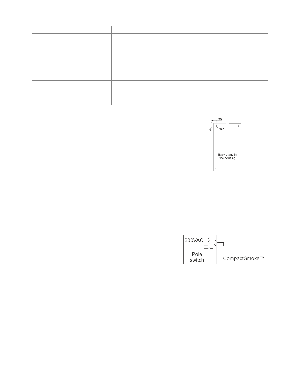
6 Mounting
The smoke ventilation panel is fixed to the wall through the Ø8.5mm holes in the
back plane of the housing.
If the panel is fixed in different way, the holes are to be blinded with the 4 blind
grommets, this way the IP class is maintained.
The door is turnable.
When turning the door also move the blind grommets to the new holes.
The smoke ventilation panel is to be located in a safe place, protected from the
effects of fire and smoke.
7 Installation
7.1 Cable routing
For cable routing, we recommend the use of fire protected cables retaining their function E90 or E30.
See also chapter 8 “Cable dimensioning” in this instruction.
However, this has to be agreed with the Engineer or, if necessary, with the local fire protection department.
Do not reduce the cable cross sections specified in the cable lengths table.
All cables of the control (except the mains supply cable) carry 24V DC and have to be routed separate from the mains supply
cable.
Adhere to the pertinent national and local regulations when routing the cables.
7.2 Cables into housing
All connection terminals (except the mains terminals) are of the plug-in type.
Connect the connection cables in accordance with the terminal plan. Ensure that the connections are made correctly.
Incorrect cable clamping, mixing up numbers or colours could lead to malfunctions of the control panel or of the external
components.
Ensure that the electrical cables are always routed according to the valid national and local regulations.
7.3 Connection of safety earth wire and 230V AC
See chapter 10 ‘Description of cards’, section 10 for further description.
7.4 Installation of the break glass unit, ventilation keypad and smoke detector
Ensure that the break glass unit and the ventilation buttons are visible and well accessible. Do not install behind protruding
walls, door panels or hidden by the building structure.
Note: Installation height of the break glass unit 1.5 – 1.7m above floor.
Install the smoke detectors in accordance with their enclosed instructions.

12
7.5 Assembly instructions
Always have assembly, installation, repair and maintenance of smoke and heat extraction systems carried out by
qualified personnel trained for this purpose.
Rules to be adhered to for setting up and installation
The following safety relevant rules have to be adhered to when planning the use of a smoke and heat extraction system and its
set-up and installation:
• The Provincial Building Ordinance of the provinces,
• The regulations of the competent fire protection authority,
Accident prevention regulations
Adhere to the general accident prevention regulations (APR), the APR for power operated windows and doors, and the
installation rules in your country.
CAUTION:
Live components are directly accessible after opening the system housing.
Prior to inserting / removing cards disconnect to the panel from the mains supply and the back-up batteries.
• adhere to the installation instructions and your local energy providers
• select the place of installation such that free access is guaranteed for maintenance purposes
• select cables according to regulations in this instruction - take the calculation of the actuators supply cable lengths
into account when laying the cables
• power cables entered via the cable glands
• connect the cables in accordance with the drawings provided by the manufacturer
• route the cables in the building according to the regulations in this instruction
• after the smoke panel is installed the back-up batteries will be fully charged after ca. 8 hours
• check all system functions
Electric cable routing for smoke and heat extraction systems
Electrical cables always have to be laid in accordance with the national and local rules in your country.
Do not use the PE wire / green/yellow wire!
Cables of type NYM, concealed, can be used.
For surface laying, halogen free safety cables are recommended (see cable plan).
If possible, the use of cable types should be agreed with the Technical Services and the competent fire protection authority.
For the maximum permissible cable lengths of the actuator supply cables for the WSC 3xx system, taking the specified cable
cross sections into account (cable information for surface laying), please refer to chapter 8 “Cable dimensioning”.
8 Cable dimensioning
8.1 Maintaining the cable functions
According to valid national regulations.
The cable network for smoke ventilation systems (“Cable system“) ends normally at the interface (junction box) for the actuator!
The flexible, heat resistant connection cable of actuator is part of the system component‚ electric actuator actuation, and is not a
part of the electrical installation!
We recommend in all cases to discuss the type of cable routing with the competent fire fighting authorities.
8.2 Max. cable Length
Maximum permissible cable length from the smoke ventilation panel to the actuators taking into account the cable cross-section
is shown in the following tables for “± 24V standard actuators“ and “MotorLink® actuators“.
8.2.1 Formula for the calculation of the maximum actuator cable length
Max. cable length = permissible voltage drop 2V (UL) x conductivity of copper(56) x cable cross section in mm2 (a)
max. actuator current total in amps (I) x 2
For both ±24V standard actuators and actuators with MotorLink® the cross section of the cable must not be less than 0.75mm2
regardless of the result of above formula.
Maximum actuator cable length: Always measured from the smoke to the last junction box
Permissible max. voltage drop in the line: 2 Volt
Actuating current: Sum of all actuator power consumption per motor line
Note: do not use the PE wire / green/yellow wire!
Example
Max actuator cable length with cable cross section 0.75mm2 and actuator current 2A: (2 x 56x0.75) : (2 x 2) = 21m
13
8.2.2 Max cable length – ±24V standard actuators
The actuator supply cable must have 3 wires: 2 wires current carrying / 1 wire for monitoring.
±24V standard actuators
Do not use the PE wire / green/yellow wire!
cable cross
section [a]
Total
actuator current [I]
3 wire
0,75mm²
3 wire
1,50 mm²
5 wire
1,50 mm²
2 wire
parallel
3 wire
2,50 mm²
5 wire
2,50 mm²
2 wire
parallel
3 wire
4,00 mm²
1A
42m
84m
168m
140m
280m
224m
2A
21m
42m
84m
70m
140m
112m
3A
14m
28m
56m
47m
93m
75m
4A
11m
21m
42m
35m
70m
56m
5A
8m
17m
34m
28m
56m
45m
6A
7m
14m
28m
23m
47m
37m
7A
6m
12m
24m
20m
40m
32m
8A
5m
11m
21m
18m
35m
28m
9A
9m
18m
15m
31m
25m
10A
8m
16m
14m
28m
22m
20A
4m
8m
7m
14m
11m
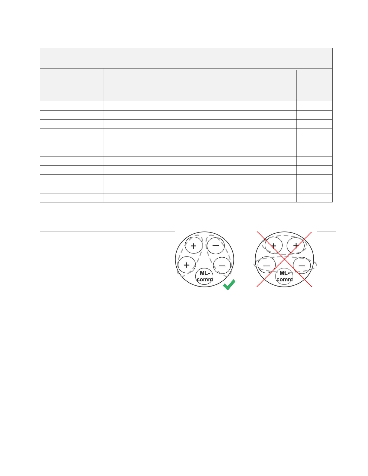
8.2.3 Max cable length – actuators with MotorLink®
The actuator supply cable must have 3 wires: 2 wires current carrying / 1 wire for communication.
When a 5 wire cable is used for MotorLink®
It is not recommended to use parallel-wire.
ML-comm = MotorLink® communication.

14
When using actuators with MotorLink® the max cable length is 50m regardless of the result of the above mentioned formula.
Actuators with MotorLink®
Do not use the PE wire / green/yellow wire!
cable cross
section [a]
Total
actuator current [I]
3 wire
0,75mm²
3 wire
1,50 mm²
5 wire
1,50 mm²
2 wire
parallel
3 wire
2,50
mm²
5 wire
2,50 mm²
2 wire
parallel
3 wire
4,00 mm²
1A
42m
50m
2A
21m
40m
50m
3A
14m
28m
50m
47m
50m
4A
11m
21m
42m
35m
5A
8m
17m
34m
28m
50m
45m
6A
7m
14m
28m
23m
47m
37m
7A
6m
12m
24m
20m
40m
32m
8A
5m
11m
21m
18m
35m
28m
9A
9m
18m
15m
31m
25m
10A
8m
16m
14m
28m
22m
20A
4m
8m
7m
14m
11m
15
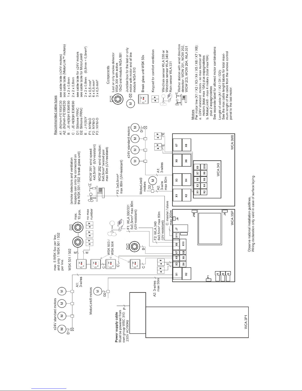
9 Cable plan for connection to WSC 310 / 320 Plus version
The above plan shows a WSC 310 panel, where the power supply unit is located in the left side of the panel wherefrom also mains
is pulled. The power supply unit for the WSC 320 panel is located underneath the main control and motor line card and mains is
pulled from the top right side. See section 10.1 for illustrations.
16
10 Description of cards and mains connection
Each panel includes a power supply unit (SMPS) and a main control card. Motor line can input cards for additional motor lines and
inputs (e.g. for key pads) as well as a fieldbus card can be added when necessary.
The size of the power supply unit determines the size of the panel and the number and/or types of actuators, which can be
connected to the panel. See table with overview of max number of allowed actuators per motor line/panel (chapter 3.2).
The size of the power supply also determines the physical design of the panel inside the cabinet and thereby eg. where mains is
connected to the main control board (WCA 3SP).
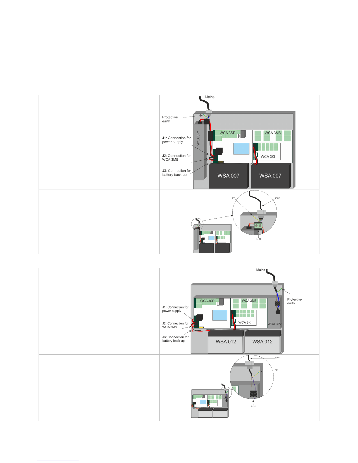
10.1 WSC 310 mains connection and power supply unit (WCA 3P1)
WSC 310 – WCA 3P1
With 300W SMPS unit
The power supply is located to the left of the main
control card.
The cable inlet is in the top left corner of the panel.
The panel must be grounded by means of protective
earth on the top panel plate.
10.2 WSC 320 mains connection and power supply unit (WCA 3P2)
WSC 320 - WCA 3P2
With 600W SMPS unit
The power supply is located underneath the main
control and the motor line card.
The cable inlet is in top right corner of the panel.
The panel must be grounded by means of protective
earth on the top right side of the panel.
17
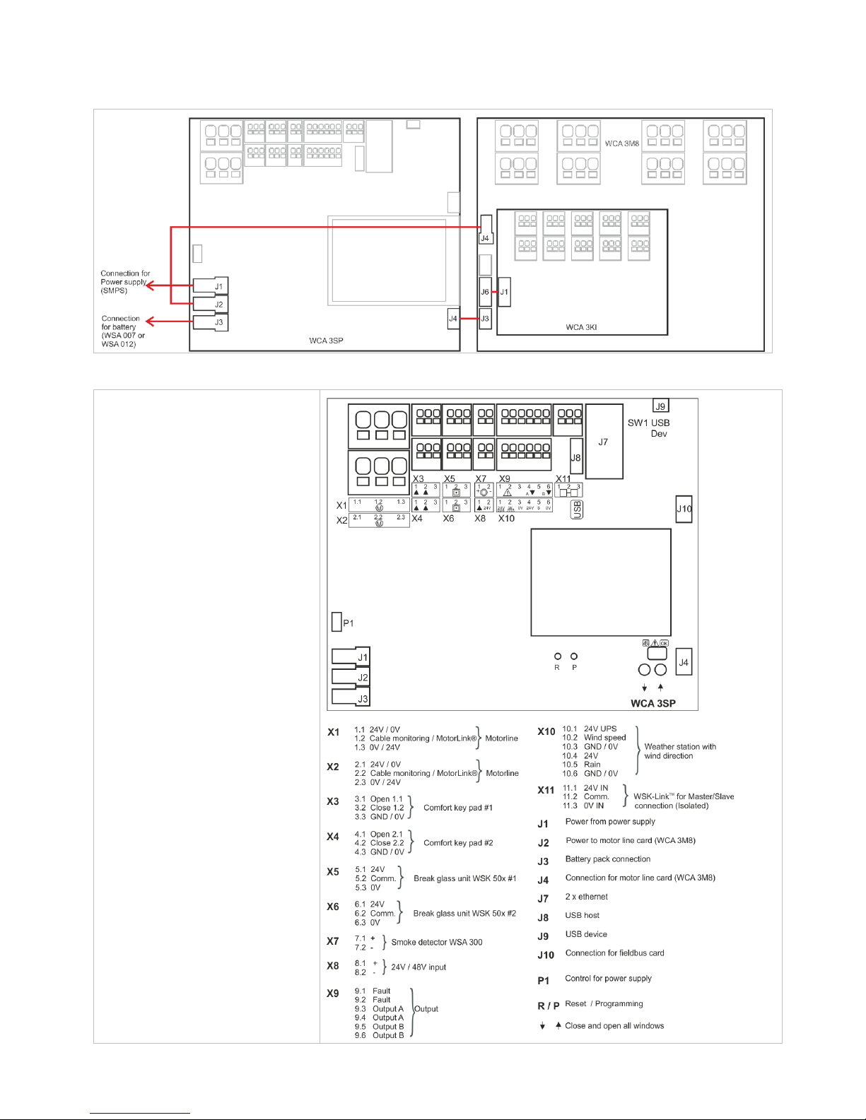
10.3 Connections between cards
An overview of how the different cards are connected are shown below.
10.4 Main control card WCA 3SP – Plus Version
Each WCA 3SP contains the
following:
- 2 motor lines for ±24V
standard or Motorlink® actuators
- 2 input for keypads for comfort
ventilation
- 2 input for break glass units
- 1 input for smoke detector
- 1 input for 24V/48V
- Output for fault signal to Fire
Alarm System
- Input for weather station incl. wind
direction (WLA 330 / 331 / 340 /
WOW 201 / 202)
- Input for master / slave connection
(ISO line)
- connection of power supply
- Power for motor line card
- Connection for battery back-up
- Connection for motor line card
- Two connections for Ethernet
- Connection for USB host and
USB device
- Connection for fieldbus card
- Touch screen for configuration,
commissioning and maintenance
18
X1 / X2
The WCA 3SP card has 2 motor lines (X1 and X2) for connection of ±24V standard or MotorLink® actuators.
±24V standard actuators
1.1 24V / 0V
1.2 Cable monitoring
1.3 0V / 24V
2.1 24V / 0V
2.2 Cable monitoring
2.3 0V / 24V
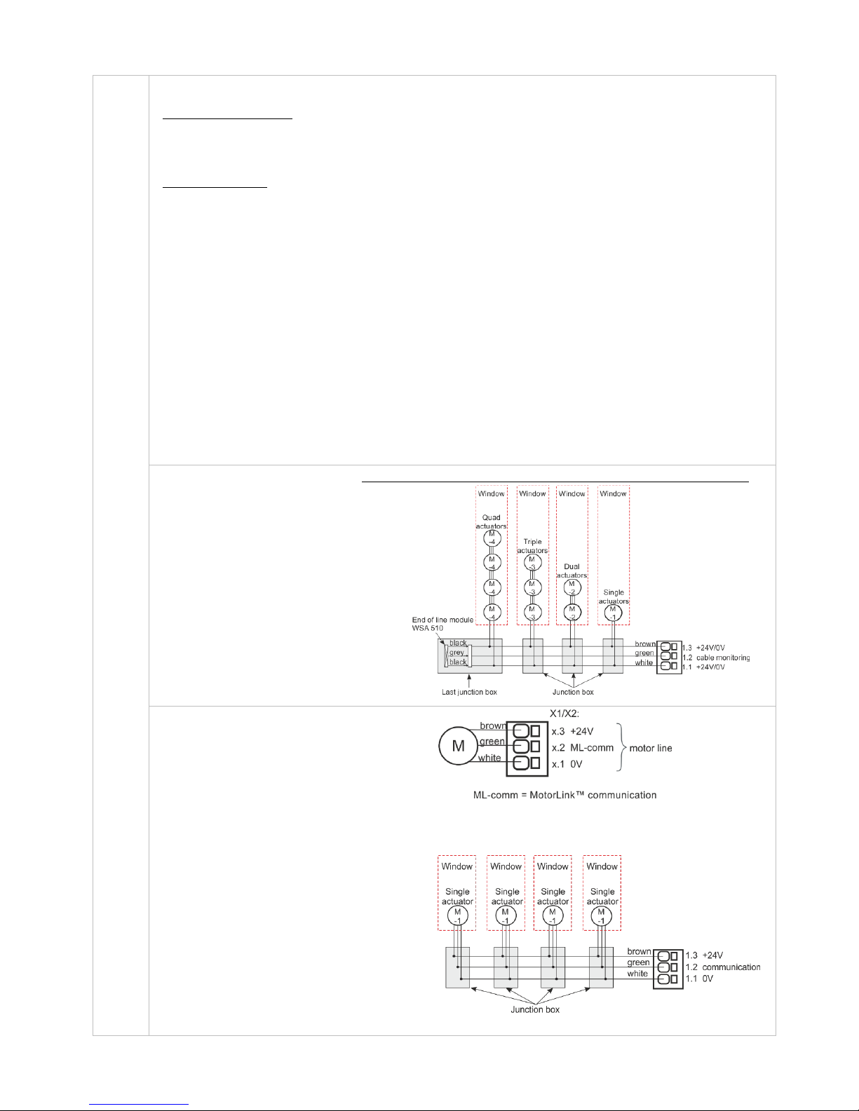
MotorLink® actuator
1.1 0V
1.2 Communication
1.3 24V
2.1 0V
2.2 Communication
2.3 24V
The number of actuators per motor line depends on the actuator type, the total power consumption of actuators
connected to a motor line can max be 10A and the total max power consumption for both motor lines must not
exceed 10A or 20A depending on panel type.
Besides actuators, also locking actuators (espagnolettes actuators) type WMB 801/802 and WMB 811/812 can
be connected. The power consumption of the locking actuators are not to be included in the 10A / 20A as
actuaators and locking actuators do not run at the same time.
All actuators on the same motor line will run/be operated simultaneously.
All actuators on the same motor line must be of the same type.
Connection / cable diameter: flexible max 6 mm² / solid max 10 mm².
Cable length: see the chapter "Cable dimensioning".
If cable monitoring is wanted, an “end of line motor module” type WSA 510 must be added in the last junction
box. When using non-WindowMaster actuators the WSA 510 is added and the cable monitoring is set to
“simple”, see section “Cable monitoring of Actuators”.
Standard ±24V actuators
Examples with 20A power
consumption
a) 20 pcs. WMX 826-1
b) 10 sets of 2 pcs. WMX 826-2
c) 4 pcs. WMU 885-1
d) 2 sets of 2 pcs. WMU 885-2
Connection of standard actuators on motor line X1 (with cable monitoring)
MotorLink® actuators
Examples with actuators per
motor line
Ex. 1: 4 pcs. WMX 823-1
Ex. 2: 2 pcs. WMX 885-2
Ex. 3: 3 pcs. WMU 826-3
Allowed actuator combinations on a MotorLink® motor line
The two motor lines on the SP card can each be connected to one of the below shown combinations.
-1 (single): one window with one single window
actuator. Up to four windows each with one
single window actuator can be connected
-2 (double): one window with two double window
actuators.
-3 (triple): one window with three triple window
actuators.
-4 (quad): one window with four quad window
actuators.
 Loading...