

Page 1
WSC 304 6102 install 1806-UK ©WindowMaster 2009, 2018 ®WindowMaster is a registered trademark used under licence by WindowMaster International A/S
WindowMaster International A/S, Skelstedet 13, DK-2950 Vedbæk
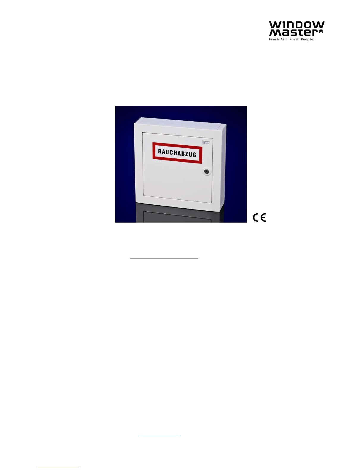
WSC 304 6102
Smoke control unit
Operating manual / Technical information
Table of contents:
Safety information
Operating elements and fuse review
Technical data
Installation
Cable lengths table
Cable plan
Standard wiring diagram
Various wiring diagrams
Commissioning
Maintenance
DK +45 4567 0300 [email protected]
DE +49 (0) 40 87 409 -560 Vertrieb / -484Technik [email protected]
CH +41 (0) 62 289 22 22 [email protected]
UK +44 (0) 1536 614 070 [email protected]
Page 2

Safety information
__________________________________________________________________________
2
Only allow correspondingly trained, qualified
and skilled personnel to carry out installation work.
Reliable operation and the avoidance of
damage and hazards is only guaranteed if
installation and settings are carried out carefully
in accordance with these instructions.
Check the technical data on the system plate.
Hazards to persons ensuing from flaps and
wings operated by electric motors.
The forces occurring in the automatic mode can
be such that parts of the body could get crushed.
When open
ed, actuators could protrude into the
room.
For this reason, measures have to be taken
prior to starting up the actuators which exclude
the danger of injury.
With wings tilting inwards or outwards, the wing
must be protected from hinging down once the
actuator is unhooked (e.g. for window cleaning).
For safety reasons we recommend the use of
catching shears.
In the event that wings or flaps are subjected to
high wind loads, we recommend to connect the
central control unit to a wind detector which
will
automatically close the flaps.
The fastening methods are exclusively intended
for the intended use for which they are designed
The manufacturer does not assume any liability
for possible damage resulting from inappropriate
use.
Can cause death, severe injury or considerable
damage to assets.
The connection of the control system is reserved
for qualified personnel.
Disconnect all poles of the unit from the supply
voltage prior to opening, installation or
assembling. Adhere to the national regulations.
230V AC dangerous voltage
Field of application
Maintenance work
Cable routing and electrical connection
Leave the insulation of the power supply
cable in place up to the mains terminal.
Manufacturer's declaration
The central control system is exclusively designed
for the automatic closing of smoke extraction
systems, windows, flaps or doors.
Always check that your system meets the valid
regulations.
Pay particular attention to the opening cross section,
the opening time and opening speed. The cable cross
sections depend on the cable length and current
consumption (amperage).
Where devices are used in smoke and heat
extraction systems, ensure that they are checked,
maintained and, if necessary, repaired a
t least once
per year.
Remove all soiling from the devices,
check the fastening and clamping screws for firm
seating. Trial run the entire system.
Defective devices may only be repaired in our factory
Only use original spare parts.
The supplied accumulators are subject to regular
checks and must be replaced every 4 years.
Fuse the 230V AC power supply cable separately on
site.
Adhere to the DIN and VDE regulations (Germany)
or equivalent in your country.
Establish the cable types, if necessary, wi
th the local
approval bodies or the fire protection authority.
Do not conceal flexible cables. Junction box
must be accessible for maintenance purposes.
Disconnect all poles of the mains voltage and the
accumulators prior to starting maintenance work or
making changes to the system.
Secure the system to prevent unintentional switching
on again.
Design cable types, lengths and cross sections in
accordance with the technical information.
Route all low voltage cables (24V DC) separate from
the power
current cables.
The devices have been inspected and manufactured
in accordance with the European directives.
A corresponding manufacturer's declaration is
available.
You are only authorised to use the devices if a
conformity declaration is issued for the entire system.
.
Attention!
Adherence to the following information is mandatory:
Page 3
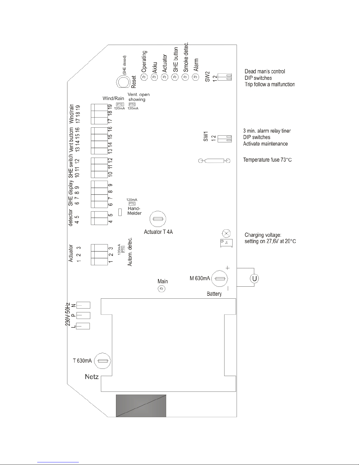
Operating elements and fuse review
____________________________________________________________________________
3
Page 4

Technical data
____________________________________________________________________________
4
Smoke and heat extraction system alarm trip:
The acoustic signal will only sounds in the break glass unit if the door is closed or if the door contact switch is
pressed.
Break glass unit:
Break the glass in the break glass unit! Press the red button min. 0,5 sec.. The smoke extraction opens.
An acoustic alarm signal sounds (continuous sound) in the break glass unit.
All ventilation functions are out of operation.
Display: The red alarm LED in the smoke control unit and the red LED in the break glass unit are lit.
Smoke detector:
If smoke develops, the smoke extraction system automatically opens.
An acoustic alarm signal sounds (continuous sound) in the break glass unit.
All ventilation functions are out of operation.
Display: The red alarm LED in the smoke control unit, the red LED in the break glass unit, and the red LED at
the tripped automatic detector are lit.
Reopening the actuators
The first 30 min. after a SHE-trig the actuators will be cyclically activated every 2 min in OPEN direction (to
loosen frost fastened windows, domes e.g.).
Resetting a tripped smoke control unit:
Press the „CLOSE button“ in the break glass unit or the „Reset button” in the smoke control unit.
The acoustic alarm signal in the break glass unit stops sounding.
The ventilation functions are operational again once the smoke extraction system has closed.
(Prior to resetting, blow out or replace the detector after it was tripped by an automatic detector).
Display: The red alarm LED in the smoke control unit, the red LED in the break glass unit, and the red LED at
the tripped automatic detector extinguish.
Resetting a trip caused by high temperature:
The smoke extraction system can be closed again by pressing the „Reset button“ in the smoke control unit or
the „CLOSE button“ in the break glass unit.
After operating the CLOSE function, an acoustic pulse tone sounds, and the flashing malfunction LED is only
displayed in the break glass unit. The green operation LED remains lit as a special fault diagnosis.
Operating the ventilation button, OPEN or STOP will lead to the tripping of another alarm.
Note:
The built-in thermal switch will then be irreversibly destroyed. The smoke control unit has to be returned for
checking.
Option: Alarm trip caused by a malfunction signal:
When this function is activated (SW2/1 = ON), the smoke control unit will trip in the event of a motor, smoke
detector or break glass unit circuit malfunction. An acoustic alarm signal sounds (continuous sound) in the
break glass unit.
If the temperature exceed 73°C the automatically SHE-alarm will be activated.
An acoustic alarm signal in the smoke control unit will start.
No trip occurs as a result of a malfunction in the mains or battery circuit.
Display: The red alarm LED in the smoke control unit and the red LED in the break glass unit are lit.
The yellow malfunction LED in the break glass unit and the corresponding yellow malfunction
LED in the smoke control unit flash.
Option: Accumulative signalling of the alarm or malfunction signal
Module WSA 301:
It is possible to send an alarm or malfunction signal potential free, by plugging in the alarm/malfunction
signalling module.
The sending of the alarm can be stopped. If this is done, the yellow LED on the module will lit.
Page 5

Technical data
____________________________________________________________________________
5
Cascading smoke control units:
The smoke control units can be cascaded by a monitored 2 wire connection from the alarm module of the
master smoke control unit to the smoke detector input of the slave central panel.
A malfunction in the cascaded smoke control units is detected via the 2 wire BUS cable. The malfunction is
only displayed in the corresponding smoke control unit and in the break glass unit connected to the master
smoke control unit.:
Ventilation functions:
Ventilation OPEN:
With the dead man's circuit activated (SW2/2 = ON), the actuators only move open for as long as the OPEN
button of the ventilation button is kept pressed.
If no dead man's function is activated (SW2/2 = OFF), the actuators open after pressing the OPEN button
(self hold).
Display: The ventilation open LED in the ventilation button is lit (only with LED integrated in the button).
Ventilation stop:
The actuators stop when both buttons are pressed.
Display: The ventilation open LED in the ventilation button remains lit (only with LED integrated in the button).
Ventilation closed:
The actuators close after pressing the CLOSED button.
Display: The ventilation open LED in the ventilation button has extinguished (only with LED integrated in the
button).
Option: Ventilation time module
Timemodule WSA 303:
Time to be set between 1 and 30 min. Once this time has elapsed, the actuators close after ventilation „OPEN“
or ventilation „STOP“. This function is not operative if the setting potentiometer is on the right-hand stop.
Wind/rain CLOSE:
The actuators close when the wind/rain sensor has tripped (potential free contact in the sensor switches). The
ventilation functions are out of operation as long as a tripped situation is pending.
The tripped signal is shown with the green wind/rain LED.
Alarm tripping has 1. priority.
Option: Transmission of the wind/rain signal
Module WSA 302:
The trip signal of the wind/rain sensor can be transmitted potential free to the next smoke control unit.
CLOSE after a power failure:
2 minutes after a power failure actuators opened for natural ventilation will automatically.
In the event of alarm, this function will be out of operation.
General information:
EMC protection:
All inputs and outputs are protected from coupled in interferences.
Short-circuit protection:
All outputs are protected against short-circuit and overload.
Page 6
Technical data
____________________________________________________________________________
6
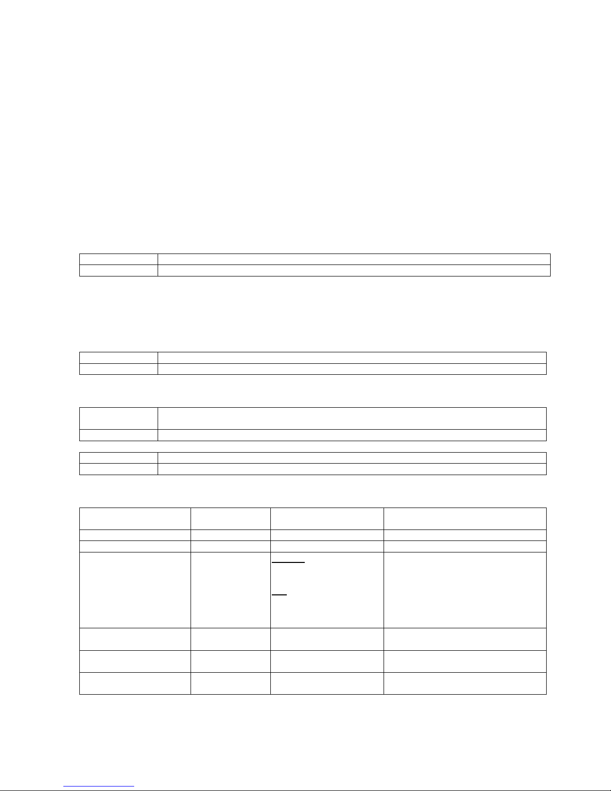
Connection possibilities:
1) Actuators with a total power consumption of max. 4A
2) Smoke detectors, up to 10 pieces in 1 sensor group
Optical smoke detector and/or thermo-differential sensor
and/or heat max. sensor WSA 300, WSA 310
3) Break glass units (main), up to 4 per sensor group WSK 320 000X
4) Break glass units (secondary), up to 15 WSK 330 000X
5) Ventilation buttons with ‘indicator, up to 15,
any number without ‘open’ indicator WSK 100 1161
6) Wind/rain detector with potential free close contact WLA 330 01, WLA 331 01
7) SHE activation on potential free
ASV contact in the smoke sensor entrance WSA 306 install
Operation / LED diagnose
Pushing the reset button on the circuit board the SHE activation is reset and the actuators closes.
Setting possibilities via slide switch SW1
SW 1/1 = ON
Inspection indication activated
SW 1/1 = OFF
Inspection indication not activated. After activation only a coded deactivation is possible
To show the activation the LED will flash 10 sec. If this time SW1/1 is once again set on OFF, the prioritised
activation is cancelled.
After a period of 12 month the inspection indication will be activated: the yellow fault LED in the main break
glass unit will flash and the audible fault alarm will sound. The green operating LED will still flash to show that
there is no fault. An alarm signal has first priority.
SW 1/2 = ON
Forwarding the alarm signal (WSA 301). After 3 min. it will stop.
SW 1/2 = OFF
Forwarding the alarm signal (WSA 301) as long as the alarm is trigged.
Setting possibilities via slide switch SW2
SW 2/1 = ON
The SHE alarm trips when malfunction signal from actuator, smoke sensor, break glass
unit, max. temperature sensor.
SW 2/1 = OFF
No SHE alarm tripped when malfunction signal. Malfunction only shown on the LEDs.
SW 2/2 = ON
The actuators only open for as long as the ventilation button is pressed (dead man control)
SW 2/2 = OF
The actuators opens all up when the ventilation buttons is pressed (self hold)
Diagnosis / monitoring in the control unit and fault elimination
LED on the
circuit board
Function is OK
Malfunction
Diagnose
Mains (green)
Lit
Off
Check mains voltage and mains fuse
Operation (green)
Lit
Off
Check all functions
Battery/load control
(yellow)
Off
Flashes when main failure
or when charging voltage
is under 26V.
Lits when
battery no connection,
battery fuse defect,
Battery voltage under 19V
Check main fuse and charging
voltage.
Check battery connection.
Check battery fuse.
Check battery voltage
Motor circuit (yellow)
Off
Flashes when interrupted
Check actuator fuse and
actuator end module
Break glass unit (yellow)
Off
Flashes when interrupted.
Lits when short circuit.
Check wiring and jumper J1 in the last
or only break glass unit.
Smoke detector (yellow)
Off
Flashes when interrupted.
Lits when short circuit
Check wiring and the active end
module.
Battery and actuator circuit malfunction be about 8 sec. delayed.
Page 7

Technical data
____________________________________________________________________________
7
Operation / LED diagnose
Alarm (red)
Lits when trigged
Wind / rain (green)
Lits when trigged
Battery charge
Charging voltage: 26,5V to 29V. depending on the surrounding temperature.
Charging current: 350mA, current restricted.
Short-circuit monitoring of the connection cables.
Charging voltage disconnected in the event of a short-circuit.
Note
Replace the emergency power batteries every 4 years!
Optional plug-in modules
Multi malfunction warning module (WSA 301):
Multi malfunction warning:
1 x change-over contact (max. load: 60V, 1A) with 3 pole connection terminal for potential free transmission
to the BMS / panel etc.
2 pole connection terminal for 2 wire BUS cable for the feedback of malfunctions in cascaded control units to
the break glass unit connected to the master smoke control unit.
Alarm message:
1 x change-over contact (max. load: 60V, 1A) with 3 pole connection terminal for potential free transmission
to BMS / panel etc., or as monitored 2 wire alarm cable for cascading control centres.
Jumper plugged in J1 = Only for the alarm transmission to the next smoke control unit (cascading).
Jumper plugged in J2 = pot.-free alarm contact (factory setting).
The transmitting can be interrupt. If so, it will be shown by the yellow LED.
Wind/rain relaying module (WSA 302):
1 x change-over contact (max. load: 60V, 1A) with 3 pole connection terminal for potential free transmission
of the wind/rain trip.
Ventilation time module (WSA 303):
Automatic closing in the ventilation mode according to pre selected time (1 min. to 30 min.) after ventilation
OPEN or STOP was actuated.
Page 8
Technical data
____________________________________________________________________________
8
Supply voltage
230V AC / 50Hz (+10% / -15%)
Safety transformer
According EN 61558
Mains amperage
Max. 100VA
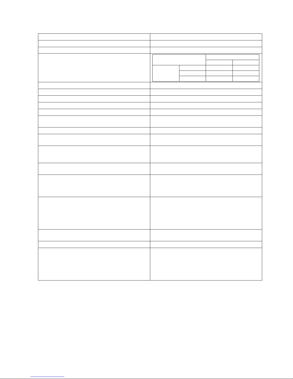
Motor output voltage
Load at actuator output
0A
4A
Main
supply
voltage
207V
25V DC
18V DC
230V
28V DC
21V DC
253V
31V DC
24V DC
Emergency power supply batteries
2x 12V / 1,9Ah. Lifetime 4 years.
Charging unit: Charging voltage
26,5V to 29V
………………………… ….. Charging current
350mA, current limited
Operating duration (emergency power supply )
72 hours if batteries are fully charged (1,9Ah)
Current load of the actuators
Max. 4A
Current load of the smoke unit
(batteries, surweillence, periphery)
Max. 0,7A
Switch-on duration
40% ED
Reopening the actuators
During the first 30 min. after a SHE-trig the actuators
cyclically every 2 min.
Review of fuses
Mains 630mA slow-blow
Motor 4 A slow-blow
Battery 630mA medium slow-blow
Type of connection to external
Mains screw terminal / plug-screw terminals / 0.5-
2.5qmm
Cable monitoring
Automatic detectors (detector circuit with active end
module), break glass unit (detector circuit with end
resistor), actuators (with motor end module), batteries
(cyclic measurement)
Message Alarm trip / malfunction
Optically alternating or steady signals by LED's.
Operating and alarm tripping = steady signal.
Malfunction of battery, actuator, break glass unit and
smoke detector in the event of an interruption =
alternating, in the event of a short circuit = steady
signal
Temperature
-5°C - 40°C.
Max. 90% relative humidity (not condensing)
Protection type
IP 30
Housing
Plastic house type UK 511 with metal door.
Build in or surface mounted (with plastic frame).
Protection class II.
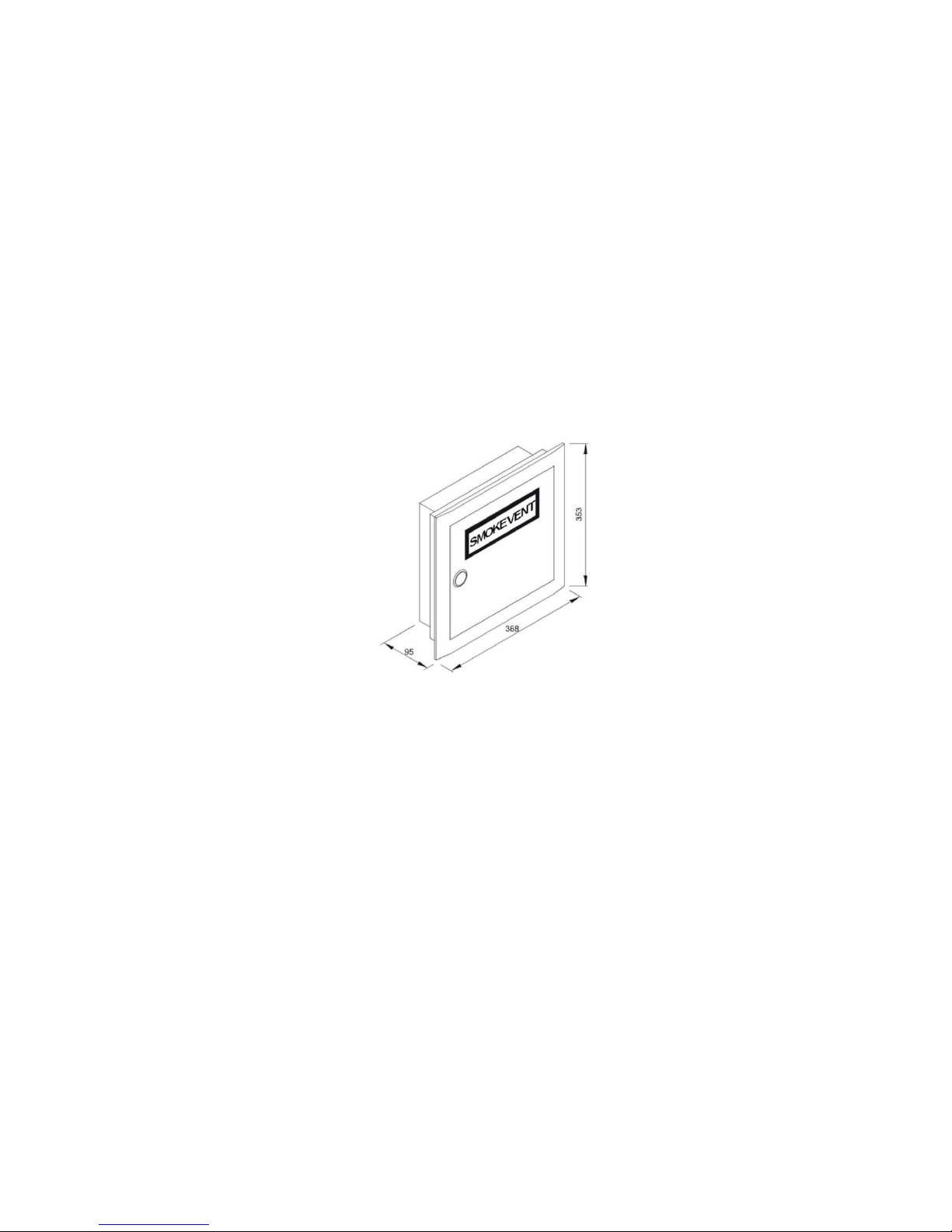
Dimensions (WxHxD) 335x350x95mm.
Cut-out dimension hole (WxDxH) 335 x 350 x 95mm.
Upgradeable with 1,9Ah to 2,2Ah batteries.
Page 9
Installation
____________________________________________________________________________
9
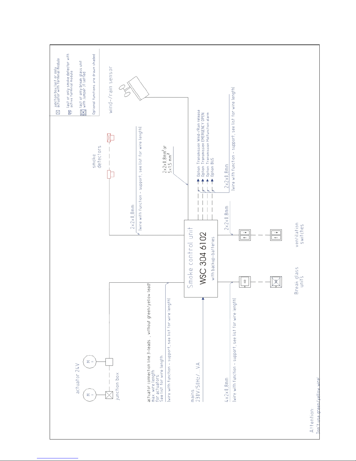
Cable routing
Observe the safety information on page 2.
For cable routing we recommend the use of fire protected cables retaining their function E90 or E30.
However, this has to be agreed with the Engineer or, if necessary, with the local fire protection department.
Do not reduce the cable cross sections specified in the cable lengths table.
All cables of the control centre (except the mains supply cable) carry 24V DC and have to be routed separate
from the mains supply cable.
Adhere to the pertinent national and local regulations when routing the cables.
Do not use the green/yellow conductor.
Ensure that the mains cable can be switched via an external or customer-supplied two-pole switch element or
a switch element controlling all poles.
Smoke unit installation
Note that the control centre has to be installed in a dry room.
Concealed housing
Refer to the sketch below for the installation position
Open central control and remove the housing
top section (door) from the housing bottom section.
Fasten the housing bottom section in the wall cut-out
(cut-out dimension 335 x 350 x 95) and
refit the housing top section.
Also possibility for surface mounting with the included frame.
Installation of the Break glass unit, ventilation buttons and detectors
Ensure that the Break glass unit and the ventilation buttons are visible and well accessible.
Do not install behind protruding walls, door panels or hidden by the building structure.
Note: Installation height of the Break glass unit = 1.4 m above floor.
Install the automatic detectors in accordance with their enclosed instructions.
Installation
Lead the connection cables into the housing of the control centre from above.
All connection terminals (except the mains terminals) are of the plug-in type.
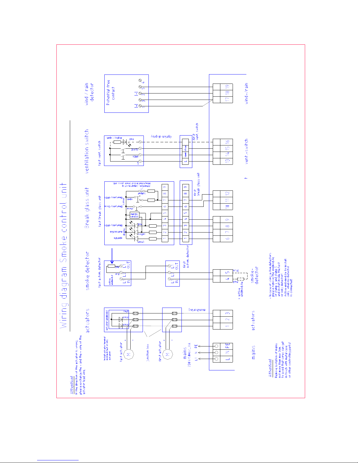
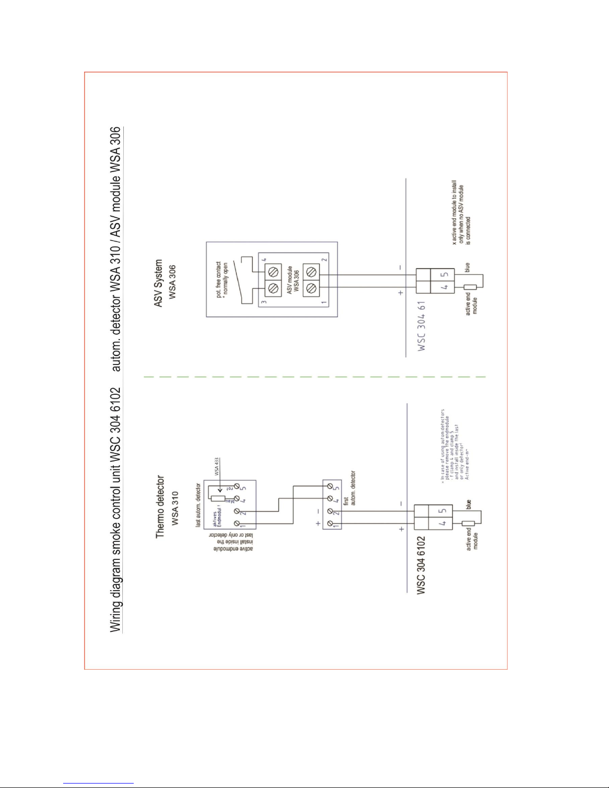
Connect the connection cables in accordance with the terminal plan. Ensure that the connections are made
correctly.
Incorrect clamping, mixing up numbers or colours could lead to malfunctions of the central control or of the
external components.
Ensure that the electrical cables are always routed according to the valid national and local regulations of the
individual country.
Page 10

Cable lengths table
____________________________________________________________________________
10
Maintaining the cable functions
According to valid national regulations.
The cable network for smoke ventilation systems („Cable system“) ends at the interface (junction box) for the
actuator!
The flexible, heat resistant connection cable of the smoke ventilation system actuator is part of the system
component ‚electric motor actuation' and does not belong to the electrical installation!
We recommend in all cases to discuss the type of cable routing with the competent fire fighting
authorities.
Cable length table
For determining the maximum permissible cable lengths between the smoke control unit and the actuators,
taking into account the specified cables cross sections, please refer to the following table:
Maximum motor current: 4A (Note: Be aware of the overall capacity of the smoke control unit!)
Maximum cable length: (always routed from the central smoke control unit to the last junction box)
Actuating current: Sum of all motor currents per group module
Note: Do not use the green/yellow wire!
Per motor supply line, 3 wires are required ( 2 wires current carrying /1 wire for monitoring )
Cross section
3 wire
5 wire
3 wire
5 wire
3 wire
1,5 mm²
1,5 mm²
2,5 mm²
2,5 mm²
4 mm²
Actuator current
in Amps
(2 wires in
parallel)
(2 wires in
parallel) 1
84,00 m
168,00 m
140,00 m
280,00 m
224,00 m
2
42,00 m
84,00 m
70,00 m
140,00 m
112,00 m
3
28,00 m
56,00 m
46,67 m
93,33 m
74,67 m
4
21,00 m
42,00 m
35,00 m
70,00 m
56,00 m
(The information is valid for ambient temperatures of 25°C)
Formula for the calculation of the maximum cable length
Permissible max. voltage drop in the line UL : 2 Volt
max. cable length = permissible voltage drop(UL) x conductivity of copper(56) x cable cross section(A)
max. actuator current total (I) in amps x 2
Permissible cable length for the break glass unit supply cable when using......4x2x0.8mm: up to 200m
The motor connection cable length to the junction box (or control module) must not exceed 10 m.
Page 11
Cable plan
____________________________________________________________________________
11
Page 12
Standard wiring diagram
__________________________________________________________________________
12
WLA 330
/ WLA331
WSA 300
WSC 304 6102
WSK 320 / WSK 33
0
First or secundary
Break glass unit
If only one break glass unit
– usa a
main break glass unit.
First or secundary Break glass unit
WsA 433
Page 13
Various wiring diagrams
____________________________________________________________________________
13
Page 14

Commisioning
____________________________________________________________________________
14
When error message occur, please refer to chapter Operating elements and fuse review.
An acoustic message only occurs in the Break glass unit with the door closed or the door contact switch
pressed!
1)
2)
Adhere to the relevant regulations! Externally disconnect the mains voltage.
3)
4)
a) Closely observe the actuators during opening and closing. They must not be impaired in any
position by the building structure. Also the motor connection cables
must not be subject to pulling or crushing.
5)
6)
The control centre is completely installed, without the operating voltage applied
only
With mains voltage, without accumulator
With mains voltage, with accumulator
Ventilation button
Break glass unit
Break glass unit (secondary)
a) Check all mechanical and electrical components for damage.
b) Check the DIP slide switches in the control centre for their correct (required) position.
c) Check all screw and plug connections for tightness and/or firm seating.
d) Check that all external components are installed.
Actuators: Is the final module at the last or only actuator inserted?
Automatic detectors: Is the active end module at the last or only detector inserted?
Manual detectors: Is the jumper inserted in the last or only operating panel?
a) Connect the mains cables and reapply the mains voltage.
b) The mains LED is ON, the operating LED is OFF, the accumulator LED is ON. The malfunction message at
the operating panels is ON.
a) Remove the protection film of the lateral adhesive tape for the 1.9 Ah battery, and firmly press the two
batteries together according to the picture (next page).
b) Remove the protection film from one face of the supplied foam rubber. Glue each foam rubber to the
bottom side of the accumulators. Connect the accumulators to the black accumulator bridge according to
the wiring diagram, then connect the red and the blue connection cable to the red and the black flat plug.
Remove the bottom protection film of the foam rubber and insert the batteries in the control unit according
to figure 1, and firmly press down to the housing bottom!
c) Plug the red connection cable to the + and the blue connection to the flat plug of the control unit. Note:
Check correct polarity!
d) The operating LED is ON, the accumulator LED is OFF. The malfunction message at the operating panels
is OFF.
b) Briefly actuate the Open button to have the actuators move open up to the final position. With the SW2/2
=ON (hold-to-run) setting, the actuators only move as long as the button is pressed. The OPEN display (if
existing) in the button is ON.
c) Briefly actuate the CLOSED button, the actuators close. The Open display is OFF.
d) Press both buttons simultaneously while running, this corresponds to stop. The ventilation Open display is
ON, the actuators stop.
e) Briefly press the Closed button again, the actuators fully close, the Open display is OFF.
a) Open the door and press the red Open button. The actuators move open through to the end position. The
red alarm LED (also in the control unit) is ON, at the same time a permanent acoustic signal sounds (door
contact pressed!).
b) While running, press the Closed button at the ventilation button, then press both buttons, the actuators
must neither close nor stop!
c) Press the reset/Closed button in the break glass unit. The actuators close through to the end position. The
ventilation function is released again. The red alarm LED (also in the control unit) and the signal generator
are OFF.
a) Check as described under 5). „Operation“, „Malfunction“ and the acoustic signal are missing!
Page 15

Commisioning
____________________________________________________________________________
15
7)
8)
d) If the actuators were open, they will automatically close after 2 minutes.
9)
10)
d) The Smoke trip has priority.
Function
description Operating elements and fuse review
wiring diagram
Automatic detectors
Emergency power supply test
Aktivation of internal check
Wind/rain detector
a) Spray test aerosol on the detectors.
b) The actuators move open through to the end position. The red LED in the detector, the red alarm LED (also
in the control unit) and the permanent acoustic signal in the operating panel are ON.
c) While running, press the Closed button at the ventilation button, then press both buttons, the actuators
must neither close nor stop!
d) Press the reset/Closed button in the operating panel. The actuators close through to the end position. The
ventilation function is released again. The red alarm LED (also in the control unit) and the signal generator
are OFF.
a) Remove the mains fuse from the control centre. Adhere to the relevant regulations!
b) The green mains and operating LED's are OFF, the yellow accumulator Led is flashing (control unit in the
accumulator mode).
The malfunction message at the break glass unit is ON.
c) The ventilation buttons are deactivated.
e) Test the SHE trip and reset/closed as described under 5).
f) Refit the mains fuse.
g) The green mains and operating LED's are ON, the yellow accumulator LED is OFF. The malfunction
message at the break glass units is OFF.
a) Disconnect the smoke vent unit from the mains and back-up batteries
b) Exchange the blind jumper J2 for active jumper J1
c) Reconnect the smoke vent unit to the mains and back-up batteries
d) The operation LED flashes app. 10 seconds to control the activation
a) Open the actuators with the ventilation button.
b) Wet the rain sensor, the actuators will fully close, the green wind/rain LED in the control centre is ON.
c) While running, press the Open button at the ventilation button, then press both buttons, the actuators must
neither open nor stop!
When the start-up was successful, then close the doors of the break glass units and of the control unit.
If the start-up was unsuccessful (error with one of the test run processes), please refer to the chapter
and . If necessary, check the wiring in accordance with the
.
Page 16

Maintenance
____________________________________________________________________________
16
The units of the smoke detection and heat extraction system have to be checked, serviced and, if necessary,
repaired at least once per year by the manufacturer or an authorised specialist company.
We also recommend the above to be carried out for pure ventilation units.
Remove all soiling from the units of the smoke ventilation system. Check fastening and clamping screws for firm
seating.
Carry out a test run of the entire system (see chapters Start-up and Test Run).
Only have defective units repaired in our factory. Only install original spare parts.
Check the operational condition at regular intervals.
We recommend to sign a maintenance contract with the manufacturer or an authorised specialist company.
All batteries coming with the smoke control unit as standard, have to be subjected to regular checks.
Within the framework of the service, they have to be replaced after the specified 4 year operating period.
Adhere to the laws governing the disposal of hazardous substances (e.g. batteries).
 Loading...